1994 JEEP CHEROKEE recommended oil
[x] Cancel search: recommended oilPage 20 of 1784
(7) Apply a small amount of chassis lubricant (or
an equivalent protective coating) to the cable termi-
nals to minimize corrosion.
RUBBER AND PLASTIC DUCTS/HOSES/TUBING
RECOMMENDED MAINTENANCE
Rubber and plastic ducts/hoses/tubing should be in-
spected at the same time the engine oil is changed
and the oil filter is replaced.
The conditions associated with vehicle operation
determines the usable life of the rubber and plastic
ducts/hoses/tubing. These conditions include:
²the extent and quality of vehicle maintenance,
²the geographic area of vehicle operation, and
²the length of exposure time to excess heat and
chemical contaminants.
DUCT/HOSE/TUBING INSPECTIONÐEXCEPT
EMISSION CONTROL HOSES/TUBING
Refer to Group 25ÐEmission Control Systems.
Engine performance could be affected by air leaks
into various hoses.
Rubber/plastic ducts, hoses and tubing should
be replaced immediately if there is any evidence
of deterioration.
(1) Inspect all hose fittings for looseness and corro-
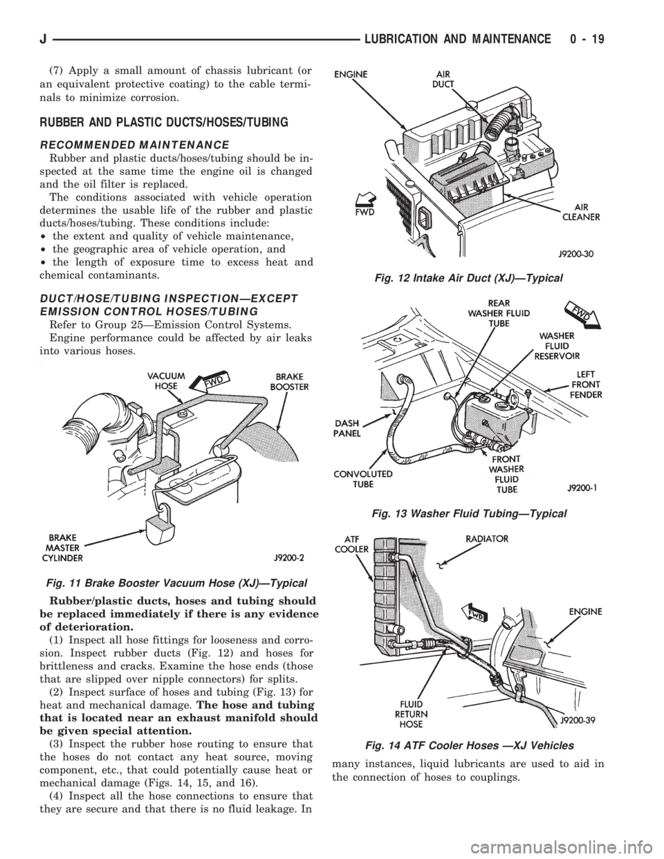
sion. Inspect rubber ducts (Fig. 12) and hoses for
brittleness and cracks. Examine the hose ends (those
that are slipped over nipple connectors) for splits.
(2) Inspect surface of hoses and tubing (Fig. 13) for
heat and mechanical damage.The hose and tubing
that is located near an exhaust manifold should
be given special attention.
(3) Inspect the rubber hose routing to ensure that
the hoses do not contact any heat source, moving
component, etc., that could potentially cause heat or
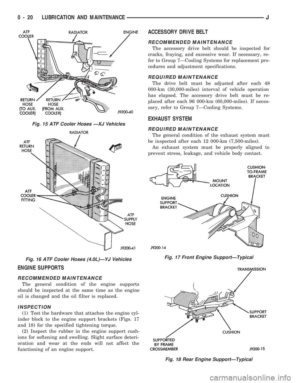
mechanical damage (Figs. 14, 15, and 16).
(4) Inspect all the hose connections to ensure that
they are secure and that there is no fluid leakage. Inmany instances, liquid lubricants are used to aid in
the connection of hoses to couplings.
Fig. 12 Intake Air Duct (XJ)ÐTypical
Fig. 13 Washer Fluid TubingÐTypical
Fig. 14 ATF Cooler Hoses ÐXJ Vehicles
Fig. 11 Brake Booster Vacuum Hose (XJ)ÐTypical
JLUBRICATION AND MAINTENANCE 0 - 19
Page 21 of 1784
ENGINE SUPPORTS
RECOMMENDED MAINTENANCE
The general condition of the engine supports
should be inspected at the same time as the engine
oil is changed and the oil filter is replaced.
INSPECTION
(1) Test the hardware that attaches the engine cyl-
inder block to the engine support brackets (Figs. 17
and 18) for the specified tightening torque.
(2) Inspect the rubber in the engine support cush-
ions for softening and swelling. Slight surface deteri-
oration and wear at the ends will not affect the
functioning of an engine support.
ACCESSORY DRIVE BELT
RECOMMENDED MAINTENANCE
The accessory drive belt should be inspected for
cracks, fraying, and excessive wear. If necessary, re-
fer to Group 7ÐCooling Systems for replacement pro-
cedures and adjustment specifications.
REQUIRED MAINTENANCE
The drive belt must be adjusted after each 48
000-km (30,000-miles) interval of vehicle operation
has elapsed. The accessory drive belt must be re-
placed after each 96 000-km (60,000-miles). If neces-
sary, refer to Group 7ÐCooling Systems.
EXHAUST SYSTEM
REQUIRED MAINTENANCE
The general condition of the exhaust system must
be inspected after each 12 000-km (7,500-miles).
An exhaust system must be properly aligned to
prevent stress, leakage, and vehicle body contact.
Fig. 17 Front Engine SupportÐTypical
Fig. 18 Rear Engine SupportÐTypical
Fig. 15 ATF Cooler Hoses ÐXJ Vehicles
Fig. 16 ATF Cooler Hoses (4.0L)ÐYJ Vehicles
0 - 20 LUBRICATION AND MAINTENANCEJ
Page 22 of 1784
INSPECTION
When inspecting an exhaust system, inspect for
cracked or loose joints, stripped screw/bolt threads,
corrosion damage, and worn or broken hangers. Re-
place all components that are corroded or damaged.
Do not attempt repair. Also, inspect for the following
obvious conditions and correct as necessary:
²exhaust system leaks, damage, misalignment;
²contact with body panels metal or the frame; and
²catalytic converter bulging or excessive heat dam-
age.
CAUTION: A catalytic converter will become con-
taminated if leaded gasoline is burned in the en-
gine. If this occurs, the complete converter must be
replaced.
AIR-CONDITIONER COMPRESSOR/HOSES/
FITTINGS
RECOMMENDED MAINTENANCE
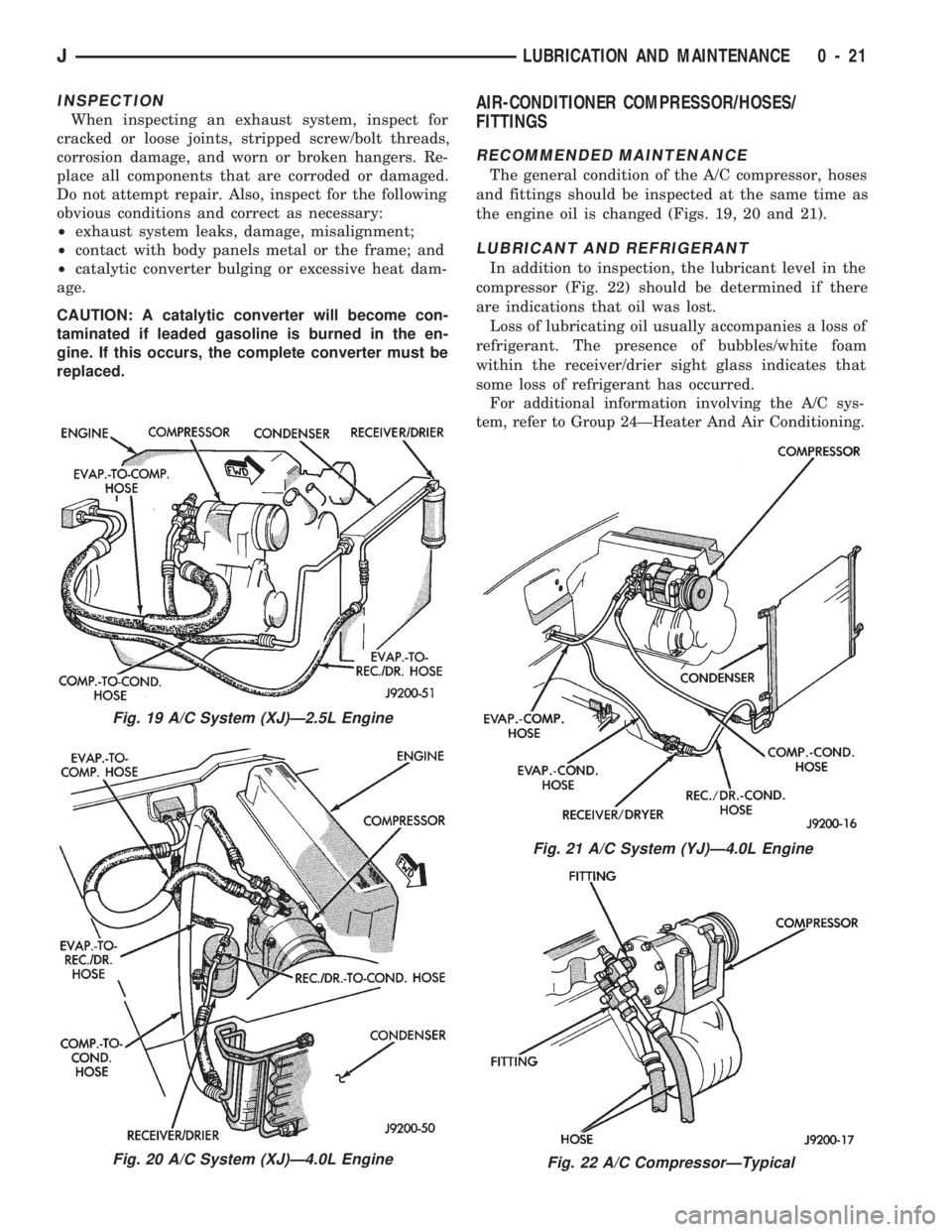
The general condition of the A/C compressor, hoses
and fittings should be inspected at the same time as
the engine oil is changed (Figs. 19, 20 and 21).
LUBRICANT AND REFRIGERANT
In addition to inspection, the lubricant level in the
compressor (Fig. 22) should be determined if there
are indications that oil was lost.
Loss of lubricating oil usually accompanies a loss of
refrigerant. The presence of bubbles/white foam
within the receiver/drier sight glass indicates that
some loss of refrigerant has occurred.
For additional information involving the A/C sys-
tem, refer to Group 24ÐHeater And Air Conditioning.
Fig. 19 A/C System (XJ)Ð2.5L Engine
Fig. 20 A/C System (XJ)Ð4.0L Engine
Fig. 21 A/C System (YJ)Ð4.0L Engine
Fig. 22 A/C CompressorÐTypical
JLUBRICATION AND MAINTENANCE 0 - 21
Page 23 of 1784
DRIVETRAIN
INDEX
page page
Automatic Transmission.................... 23
Drive Shafts............................ 27
Front and Rear Axles..................... 26
Hydraulic Clutch......................... 22Manual Transmission...................... 22
Rubber and Plastic Hoses/Tubing............ 28
Transfer Case........................... 25
HYDRAULIC CLUTCH
RECOMMENDED MAINTENANCE
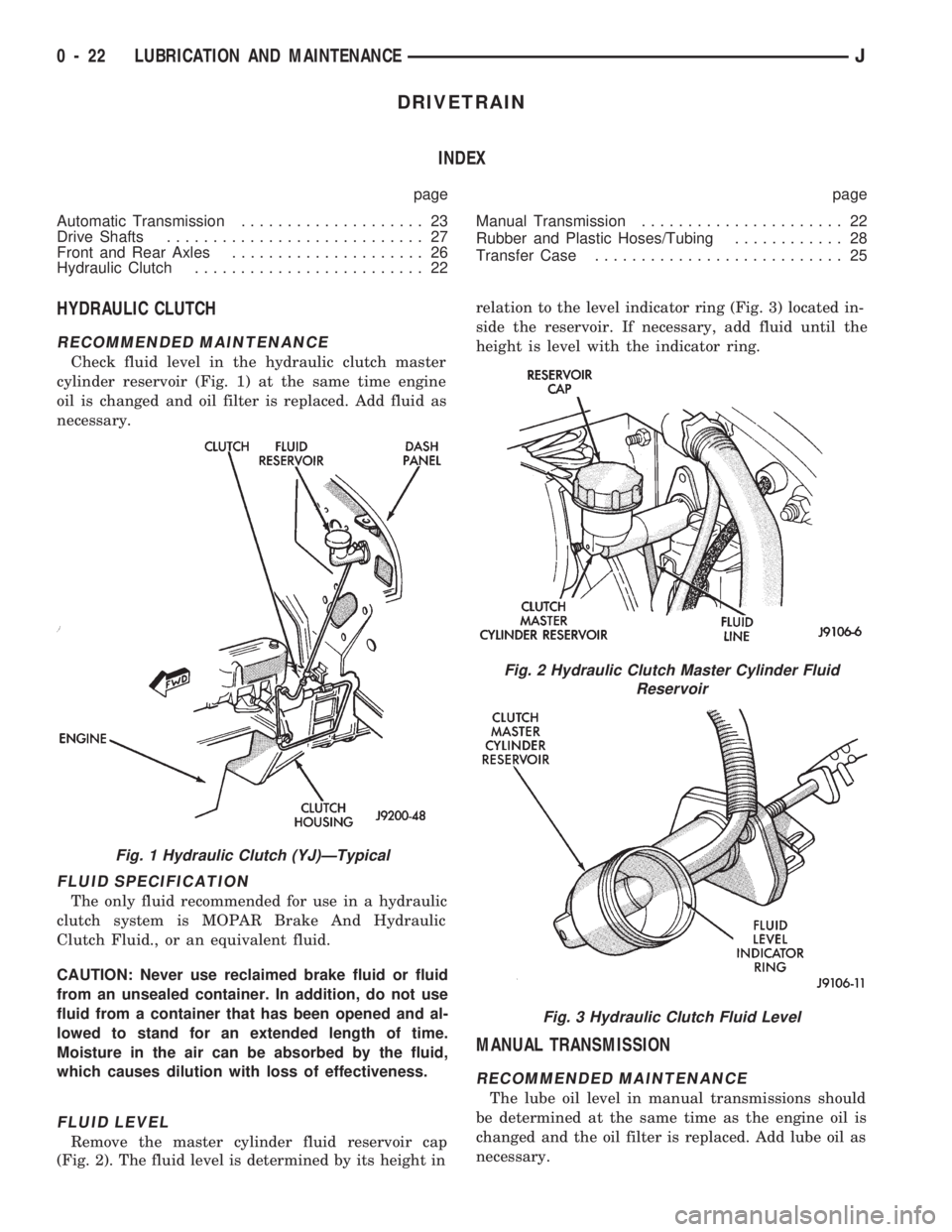
Check fluid level in the hydraulic clutch master
cylinder reservoir (Fig. 1) at the same time engine
oil is changed and oil filter is replaced. Add fluid as
necessary.
FLUID SPECIFICATION
The only fluid recommended for use in a hydraulic
clutch system is MOPAR Brake And Hydraulic
Clutch Fluid., or an equivalent fluid.
CAUTION: Never use reclaimed brake fluid or fluid
from an unsealed container. In addition, do not use
fluid from a container that has been opened and al-
lowed to stand for an extended length of time.
Moisture in the air can be absorbed by the fluid,
which causes dilution with loss of effectiveness.
FLUID LEVEL
Remove the master cylinder fluid reservoir cap
(Fig. 2). The fluid level is determined by its height inrelation to the level indicator ring (Fig. 3) located in-
side the reservoir. If necessary, add fluid until the
height is level with the indicator ring.
MANUAL TRANSMISSION
RECOMMENDED MAINTENANCE
The lube oil level in manual transmissions should
be determined at the same time as the engine oil is
changed and the oil filter is replaced. Add lube oil as
necessary.
Fig. 1 Hydraulic Clutch (YJ)ÐTypical
Fig. 2 Hydraulic Clutch Master Cylinder Fluid
Reservoir
Fig. 3 Hydraulic Clutch Fluid Level
0 - 22 LUBRICATION AND MAINTENANCEJ
Page 24 of 1784
Under normal driving conditions, manual trans-
mission lube oil should be changed after each 60
000-km (37,500 miles). With severe driving condi-
tions, after each 29 000-km (18,000 miles).
LUBRICANT SPECIFICATION
When it becomes necessary to add to or change the
lube oil in a Jeeptmanual transmission, use SAE
75W-90, API Quality Grade GL-5 gear lubricant.
LUBRICANT LEVEL
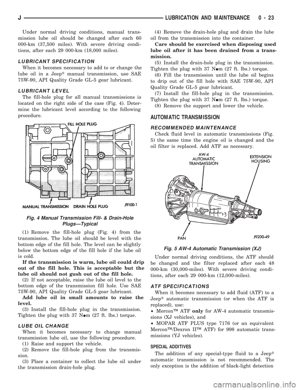
The fill-hole plug for all manual transmissions is
located on the right side of the case (Fig. 4). Deter-
mine the lubricant level according to the following
procedure.
(1) Remove the fill-hole plug (Fig. 4) from the
transmission. The lube oil should be level with the
bottom edge of the fill hole. The level can be slightly
below the bottom edge of the fill hole if the lube oil
is cold.
If the transmission is warm, lube oil could drip
out of the fill hole. This is acceptable but the
lube oil should not gush out of the fill hole.
(2) If not acceptable, raise the lube oil level to the
bottom edge of the transmission fill hole. Use SAE
75W-90, API Quality Grade GL-5 gear lubricant.
Add lube oil in small amounts to raise the
level.
(3) Install the fill-hole plug in the transmission.
Tighten the plug with 37 NIm (27 ft. lbs.) torque.
LUBE OIL CHANGE
When it becomes necessary to change manual
transmission lube oil, use the following procedure.
(1) Raise and support the vehicle.
(2) Remove the fill-hole plug from the transmis-
sion.
(3) Place a container to collect the lube oil under
the transmission drain-hole plug.(4) Remove the drain-hole plug and drain the lube
oil from the transmission into the container.
Care should be exercised when disposing used
lube oil after it has been drained from a trans-
mission.
(5) Install the drain-hole plug in the transmission.
Tighten the plug with 37 NIm (27 ft. lbs.) torque.
(6) Fill the transmission until the lube oil begins
to drip out of the fill hole with SAE 75W-90, API
Quality Grade GL-5 gear lubricant.
(7) Install the fill-hole plug in the transmission.
Tighten the plug with 37 NIm (27 ft. lbs.) torque.
(8) Remove the support and lower the vehicle.
AUTOMATIC TRANSMISSION
RECOMMENDED MAINTENANCE
Check fluid level in automatic transmissions (Fig.
5) the same time the engine oil is changed and the
oil filter is replaced. Add ATF as necessary.
Under normal driving conditions, the ATF should
be changed and the filter replaced after each 48
000-km (30,000-miles). With severe driving condi-
tions, after each 29 000-km (12,000-miles).
ATF SPECIFICATIONS
When it becomes necessary to add fluid (ATF) to a
Jeeptautomatic transmission (or when the ATF is
replaced), use:
²MerconŸ ATFonlyfor AW-4 automatic transmis-
sions (XJ vehicles), and
²MOPAR ATF PLUS type 7176 (or an equivalent
MerconŸ/Dexron IIŸ ATF) for 998 automatic trans-
missions (YJ vehicles).
SPECIAL ADDITIVES
The addition of any special-type fluid to a Jeept
automatic transmission is not recommended. The
only exception is the addition of black-light detection
Fig. 5 AW-4 Automatic Transmission (XJ)
Fig. 4 Manual Transmission Fill- & Drain-Hole
PlugsÐTypical
JLUBRICATION AND MAINTENANCE 0 - 23
Page 26 of 1784

DRAINING ATF/FILTER REMOVAL
Drain the automatic transmission fluid (ATF) im-
mediately after stopping the engine (before the ATF
cools).
(1) Raise and support the vehicle.
(2) Loosen the transmission pan bolts and drain
the original ATF into an appropriate container. Re-
move the pan bolts, the pan and the gasket.
Care should be exercised when disposing used
ATF after it has been drained from a vehicle
transmission.
(3) Remove the screws and the ATF filter (Fig. 8).
Discard the filter.
FILTER INSTALLATION/ATF RE-FILL
(1) Install a replacement ATF filter. Tighten the
screws with 4 NIm (35 in. lbs.) torque.
(2) Clean the pan thoroughly. Install a replace-
ment gasket on the pan. Install the pan with the at-
taching bolts:
²model AW-4 transmission Ð tighten the pan bolts
with 7 NIm (60 in. lbs.) torque; and
²model 998 transmission Ð tighten the pan bolts
with 17 NIm (150 in. lbs.) torque.
(3) Remove the support and lower the vehicle.
(4) Pour approximately 4.7 liters (5 quarts) of ATF
into the filler tube. Use MerconŸ ATF for AW-4 au-
tomatic transmissions. Use MOPAR ATF PLUS type
7176 or equivalent, for 998 automatic transmissions.
(5) Place a block in front of and at the rear of one
wheel/tire to prevent vehicle movement.
(6) Start the engine and allow it to idle a few min-
utes.
(7) Apply the brake pedal and engage the parking
brake. Move the transmission selector lever through
all positions, then place the selector lever in NEU-
TRAL position.(8) With the transmission at normal operating
temperature, observe the ATF level on the dipstick.
Add ATF (if necessary) to raise the level to the
FULL mark on the dipstick.Only 0.5 liter (1.0 pint)
will raise the level from the ADD mark to the
FULL mark when the ATF is at normal operat-
ing temperature.
(9) Inspect for fluid leaks and correct as necessary.
(10) Remove the wheel/tire blocks.
TRANSFER CASE
RECOMMENDED MAINTENANCE
The fluid (ATF) level in transfer cases should be
determined at the same time as the engine oil is
changed and the oil filter is replaced. Add ATF as
necessary.
In addition, transfer case ATF should be changed
after each 48 000-km (30,000-miles) interval of vehi-
cle operation has elapsed.
FLUID SPECIFICATIONS
If it is necessary to add fluid to a transfer case (or
when the fluid is changed), use MOPAR ATF PLUS
type 7176 or an equivalent MerconŸ/Dexron IIŸ
ATF.
FLUID LEVEL
The transfer case fill-hole plug is located at the
rear of the housing (Fig. 9).
Determine the transfer case fluid (ATF) level ac-
cording to the following procedure.
(1) Raise and support the vehicle.
(2) Remove the fill-hole plug from the transfer
case. The ATF level should be at the bottom edge of
the fill hole. The level can be slightly below the bot-
tom edge of the fill hole if the fluid is cold.
Fig. 9 Transfer CaseÐTypical
Fig. 8 ATF FilterÐTypical
JLUBRICATION AND MAINTENANCE 0 - 25
Page 27 of 1784
If the transfer case ATF is warm, it is accept-
able for the fluid to drip out of the fill hole. If
the fluid gushes out of the fill hole, the level is
too high.
(3) If the level is low, raise it to the bottom edge of
the fill hole with MOPAR ATF PLUS type 7176 or
an equivalent MerconŸ/Dexron IIŸ ATF.
(4) Install the fill-hole plug. Tighten the plug with
47 NIm (35 ft. lbs.) torque.
(5) Remove the support and lower the vehicle.
FLUID CHANGE
When it becomes necessary to change the ATF in a
Jeepttransfer case, use the following procedure.
(1) Raise and support the vehicle.
(2) Remove the fill-hole plug from the transfer
case.
(3) Place an appropriate container under the trans-
fer case drain-hole plug.
(4) Remove the drain-hole plug and drain the ATF
from the transfer case into the container.
Care should be exercised when disposing used
ATF after it has been drained from a transfer
case.
CAUTION: Do not over-tighten the drain and fill-hole
plugs. Over-tightening can strip the hole threads
and/or crack the aluminum housing.
(5) Install the drain-hole plug in the transfer case.
Tighten the plug with 47 NIm (35 ft. lbs.) torque.
(6) Fill the transfer case to the bottom edge of the
fill hole with MOPAR ATF PLUS type 7176 (or an
equivalent MerconŸ/Dexron IIŸ ATF).
(7) Install the fill-hole plug in the transfer case.
Tighten the plug with 47 NIm (35 ft. lbs.) torque.
(8) Remove the support and lower the vehicle.
FRONT AND REAR AXLES
RECOMMENDED MAINTENANCE
The lubricant level in axle differential housings
should be determined at the same time as the engine
oil is changed and the oil filter is replaced. Add lu-
bricant as necessary.
In addition, with normal driving conditions, the
axle lubricant should be changed after each 48
000-km (30,000-miles). With severe driving condi-
tions, after each 29 000-km (12,000-miles).
LUBRICANT SPECIFICATIONS
For normal vehicle operation, use SAE 75W-90,
API Quality Grade GL-5 gear lubricant in all Jeept
front (4WD only) and rear axles. Vehicles equipped
with a Trac-Loc rear axle also require a friction mod-
ifier additive with the gear lubricant.
When involved in trailer towing applications
use SAE 80W-140, API Quality Grade GL-5 gearlubricant in the rear axle. XJ Vehicles equipped
with a class III trailer hitch require SAE
75W-140 synthetic gear lubricant in the rear
axle.
LUBRICANT LEVEL
Determine the axle differential housing lubricant
level according to the following procedure.
(1) Raise and support the vehicle.
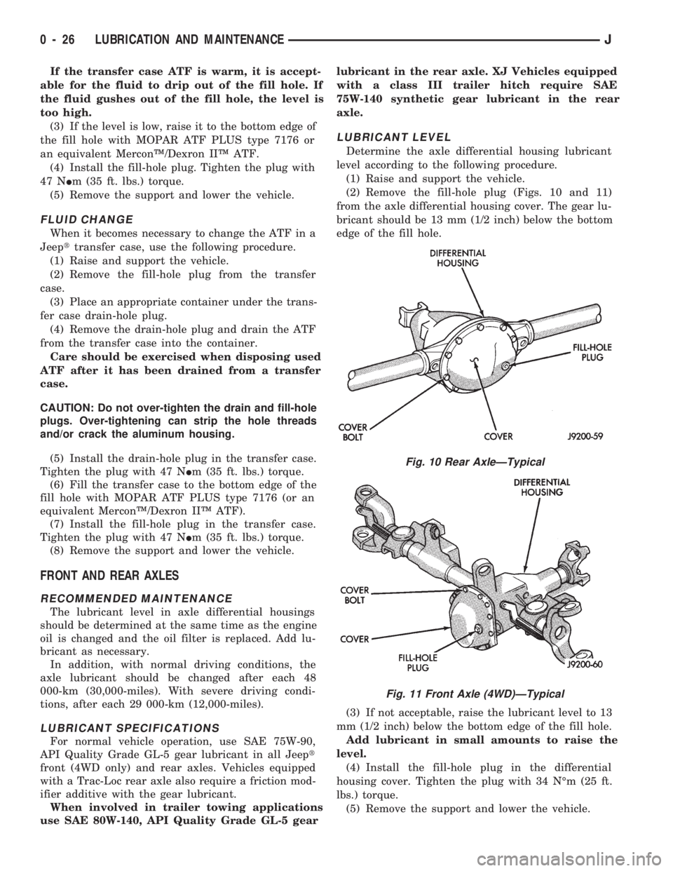
(2) Remove the fill-hole plug (Figs. 10 and 11)
from the axle differential housing cover. The gear lu-
bricant should be 13 mm (1/2 inch) below the bottom
edge of the fill hole.
(3) If not acceptable, raise the lubricant level to 13
mm (1/2 inch) below the bottom edge of the fill hole.
Add lubricant in small amounts to raise the
level.
(4) Install the fill-hole plug in the differential
housing cover. Tighten the plug with 34 NÉm (25 ft.
lbs.) torque.
(5) Remove the support and lower the vehicle.
Fig. 10 Rear AxleÐTypical
Fig. 11 Front Axle (4WD)ÐTypical
0 - 26 LUBRICATION AND MAINTENANCEJ
Page 28 of 1784
LUBRICANT CHANGE
When it becomes necessary to change the axle lu-
bricant in a Jeeptfront or rear axle, use the follow-
ing procedure.
(1) Raise and support the vehicle.
(2) Place a container under the axle differential
housing.
(3) Remove the axle differential housing cover
bolts. Remove the housing cover.
(4) Allow the axle gear lubricant to completely
drain into the container.
CAUTION: Do not flush a rear axle Trac-Loc differ-
ential. Trac-Loc differentials may be cleaned only
by disassembling the unit and wiping the compo-
nents with clean, lint-free cloth.
(5) Flush the inside of the differential housing
with a flushing oil.Do not use water, steam, ker-
osene or gasoline for flushing.
(6) Remove any residual RTV sealant/gasket mate-
rial from the differential housing and cover. Thor-
oughly clean the contact surfaces with mineral
spirits and dry the surfaces completely.
(7) Apply a`bead of MOPAR RTV Sealant, or an
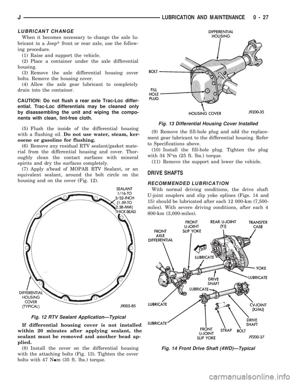
equivalent sealant, around the bolt circle on the
housing and on the cover (Fig. 12).
If differential housing cover is not installed
within 20 minutes after applying sealant, the
sealant must be removed and another bead ap-
plied.
(8) Install the cover on the differential housing
with the attaching bolts (Fig. 13). Tighten the cover
bolts with 47 NIm (35 ft. lbs.) torque.(9) Remove the fill-hole plug and add the replace-
ment gear lubricant to the differential housing. Refer
to Specifications above.
(10) Install the fill-hole plug. Tighten the plug
with 34 NÉm (25 ft. lbs.) torque.
(11) Remove the support and lower the vehicle.
DRIVE SHAFTS
RECOMMENDED LUBRICATION
With normal driving conditions, the drive shaft
U-joint couplers and slip yoke splines (Figs. 14 and
15) should be lubricated after each 12 000-km (7,500-
miles). With severe driving conditions, after each 4
800-km (3,000-miles).
Fig. 12 RTV Sealant ApplicationÐTypical
Fig. 13 Differential Housing Cover Installed
Fig. 14 Front Drive Shaft (4WD)ÐTypical
JLUBRICATION AND MAINTENANCE 0 - 27