1994 JEEP CHEROKEE front light
[x] Cancel search: front lightPage 363 of 1784

DIAGNOSINGÐALL LAMPS OUT
(1) Inspect fuse #9. Replace as required.
(2) Measure voltage at instrument cluster connec-
tor terminal 20. Meter should read zero ohms. If not,
repair open to ground.
UPSHIFT INDICATOR LAMP
Vehicles equipped with manual transmissions have
an optional upshift indicator lamp. The lamp is con-
trolled by the PCM. The lamp lights to indicate when
the driver should shift to the next highest gear for best
fuel economy. The PCM will turn the lamp off after 3 to
5 seconds if the upshift is not performed. The lamp will
remain off until the vehicle stops accelerating and is
brought back to the range of lamp operation or shifted
into another gear.
The indicator lamp is normally illuminated when
the ignition switch is turned ON and it is turned off
when the engine is started. The lamp will be lighted
during engine operation according to engine speed
and load.
(1) Turn ignition switch to ON.
(2) Ground pin 2 of cluster connector. Lamp should
light. If not, replace bulb. If OK, continue with step 3.
(3) Turn ignition switch to OFF. Check for conti-
nuity between cluster connector pin 2 and pin 54 of
the PCM. If not, repair open. If OK, refer to DRB
scan tool actuator test of upshift indicator.
BRAKE INDICATOR LAMP
The brake indicator is a dual function lamp. It will in-
dicate an unequal pressure condition in the split brake
hydraulic system and it also will indicate when the park-
ing brake is engaged. Separate switches are used for each
indicator lamp function. A switch mounted on the brake
pedal assembly will close a ground circuit whenever the
parking brakes are applied. A second switch is installed
in the brake hydraulic lines near the master cylinder. If
the switch is balanced by equal pressure on both ends of
the switch valve, the valve remains centered and the
lamp remains off. If the valve is shifted by unequal pres-
sure between the front or rear brake hydraulic systems,
the lamp circuit is connected to ground. To make sure
the brake lamp is functional before the vehicle is driven,
it is illuminated through a ground circuit when the igni-
tion switch is turned to the START position.
(1) Turn ignition switch to ON.
(2) Ground pin 1 of the cluster connector. Lamp
should light. If not, replace bulb. If OK, continue
with step 3.
(3) Turn ignition switch to OFF. Check for continuity to
park brake switch and brake warning switch.
MALFUNCTION INDICATOR LAMP (CHECK ENGINE)
The Malfunction Indicator Lamp (Check Engine) il-
luminates each time the ignition switch is turned
ON and stays on for 3 seconds as a bulb test.If the PCM receives an incorrect signal or no signal
from certain sensors or emission related systems the
lamp is turned on (pin 32 of PCM). This is a warning
that the PCM has recorded a system or sensor mal-
function. In some cases when a diagnostic fault is de-
clared the PCM will go into a limp-in mode in an
attempt to keep the system operating. It signals an
immediate need for service.
The lamp also can be used to display diagnostic
trouble codes (DTC). Cycle the ignition switch ON,
OFF, ON, OFF, ON within 5 seconds. This will allow
any DTC's stored in the PCM memory to be dis-
played in a series of flashes representing digits.
(1) Turn ignition switch to ON.
(2) Ground pin 4 of cluster connector. Lamp should
light. If not, replace bulb. If OK, continue with step 3.
(3) Turn ignition switch to OFF. Check for conti-
nuity between cluster connector pin 4 and PCM cav-
ity 32. If OK, replace PCM. If not, repair open.
SEAT BELT REMINDER LAMP
Apply 12 volts to terminal 16 of cluster connector.
Lamp should light. If not, replace bulb. If OK, check
wiring for an open to buzzer module. Refer to Group
8U - Chime/Buzzer Warning Systems.
INSTRUMENT PANEL ILLUMINATION LAMPS
The instrument panel illumination lamps share
two common connections. There is a splice after fuse
#10 that connects the lamps to battery feed. There is
also a splice that connects all lamps to ground. Be-
cause they share these common connection points in
a parallel circuit, the illumination lamps will all
come on at the same time. It also means one or more
lamps can be out without affecting the operation of
the other lamps.
On the battery side of the circuit, the headlamp
switch illumination rheostat/switch and panel lamps
fuse receive battery feed in series from the park/tail
fuse. In the park lamp position, the headlamp switch
completes the circuit from the park/tail fuse to the il-
lumination rheostat/switch and panel lamps fuse.
The illumination rheostat contains a variable resis-
tor that allows the driver to vary illumination inten-
sity from off to full brightness.
DIAGNOSIS
(1) Turn parking lamps ON.
(2) Check fuse #10. Replace as required.
(3) Measure voltage at battery side of fuse #10
with rheostat turned counterclockwise to clockwise
(LO to HI). Meter should read zero volts to battery
voltage. If not, replace headlamp switch.
(4) Measure resistance at ground side of fuse #10
with parking lamps OFF. Meter should read almost
zero ohms (except bulb filament). If not, repair open
to ground. If zero ohms, 12 volt supply wire from fuse
is shorted to ground, repair short.
8E - 16 YJ INSTRUMENT PANEL AND GAUGESJ
Page 402 of 1784

TURN SIGNALS AND HAZARD WARNING FLASHER
CONTENTS
page page
HAZARD LAMPSÐXJ.................... 1
HAZARD LAMPSÐYJ.................... 2
TURN SIGNALSÐXJ..................... 1TURN SIGNALSÐYJ..................... 2
TURN/HAZARD SWITCH REPLACEMENT - ALL
MODELS............................. 3
TURN SIGNALSÐXJ
Refer to Section 8W - Wiring Diagrams for cir-
cuit wiring diagram.
DESCRIPTION
With the turn signal lever in its up or down posi-
tion and the ignition switch in ACCESSORY or ON,
current flows through the:
²turn/hazard switch
²selected turn indicator bulb
²front and rear turn signal bulbs
²and the front side marker bulb.
With the headlamps OFF, the turn and front side
marker lamps flash in unison.With the headlamps
ON, the turn and front side marker lamps flash al-
ternately.
DIAGNOSISÐTURN SIGNAL INOPERATIVE
(1) A turn signal indicator that does not flash usu-
ally indicates a burned out turn signal bulb. Check
for and replace if defective. System should now func-
tion properly. If not, go to next step.
High generator output voltage can burn out
lamps rapidly.(2) Remove and inspect 20 amp #8 fuse. Replace if
necessary. If OK, go to next step.
(3) Remove turn flasher, light blue can, located in
upper left corner of fuse block.
(4) Turn ignition switch to ACCESSORY. Check
for battery voltage at flasher bottom cavity on fuse
block. If OK, go to next step. If not, repair open cir-
cuit in wiring between turn flasher and #8 fuse.
(5) Turn ignition switch to ACCESSORY. Move
turn signal lever up or down. Replace turn flasher
with known good flasher. The lamps should flash. If
not, replace original flasher and go to next step.
(6) Turn ignition switch to OFF. Follow procedure
for turn/hazard switch replacement to locate steering
column connector. Unplug connector.
(7) Turn ignition switch to ACCESSORY. Check
for battery voltage at connector terminal L. If OK,
replace turn/hazard switch and check that lamps
flash. If not, repair open circuit in wiring between
turn flasher and steering column connector terminal
L.
HAZARD LAMPSÐXJ
Refer to Section 8W - Wiring Diagrams for cir-
cuit wiring diagram.
DESCRIPTION
With the hazard switch ON, current flows through
the:
²hazard flasher
²the turn/hazard switch
²two front turn signal bulbs
²two rear turn signal bulbs
²two front side marker bulbs
²and two turn indicator bulbs.
All of these bulbs will flash on and off.
DIAGNOSISÐHAZARD LAMPS INOPERATIVE
(1) Inspect 20 amp #F13 fuse in Power Distribu-
tion Center (PDC). The PDC is located in the engine
compartment, passenger side. For location of fuse,check underside of PDC cover. Replace if necessary.
If OK, go to next step.
(2) Remove hazard flasher (tin can) located in fuse
block.
(3) Check for battery voltage at the terminal on
the right (3 o'clock). If OK, go to next step. If not, re-
pair open circuit in wiring between #F13 fuse and
hazard flasher right terminal.
(4) Replace hazard flasher with known good
flasher. Activate hazard warning switch. Lamps
should flash. If not, replace original flasher and go to
next step.
(5) Follow procedure for turn/hazard switch re-
placement to locate steering column connector. Un-
plug connector.
(6) Check for battery voltage at connector terminal
K. If OK, replace turn/hazard switch. If not, repair
open circuit in wiring between hazard flasher and
steering column connector terminal K.
JTURN SIGNALS AND HAZARD WARNING FLASHER 8J - 1
Page 403 of 1784

TURN SIGNALSÐYJ
Refer to Section 8W - Wiring Diagrams for cir-
cuit wiring diagram.
DESCRIPTION
With the turn signal lever in its up or down posi-
tion and the ignition switch in ACCESSORY or ON,
current flows through the:
²turn/hazard switch
²selected turn indicator bulb
²front and rear turn signal bulbs
²front side marker bulb
With the headlamps OFF, the turn and side
marker lamps flash in unison.With the headlamps
ON, the turn and side marker lamps flash alter-
nately.
DIAGNOSINGÐTURN SIGNAL INOPERATIVE
(1) A turn signal indicator that does not flash usu-
ally indicates a burned out turn signal bulb. Check
for and replace if defective. System should now func-
tion properly. If not, go to next step.
High generator output voltage can burn out
lamps rapidly.
(2) Locate fuse block under driver's side of instru-
ment panel.(3) Remove and inspect 15 amp #4 fuse. Replace if
necessary. If OK, go to next step.
(4) Remove turn flasher, light blue can, located in
fuse block.
(5) Turn ignition switch to ACCESSORY. Check
for battery voltage at cavity on left (closest to hazard
flasher can). If OK, go to next step. If not, repair
open circuit in wiring between turn flasher and #4
fuse.
(6) Turn ignition switch to ACCESSORY. Move
turn signal lever up or down. Replace turn flasher
with known good flasher. The lamps should flash. If
not, replace original flasher and go to next step.
(7) Turn ignition switch to OFF. Follow procedure
for turn/hazard switch replacement to locate steering
column connector. Unplug connector.
(8) Turn ignition switch to ACCESSORY. Check
for battery voltage at connector terminal L. If OK,
replace turn/hazard switch. If not, repair open circuit
in wiring between turn flasher and steering column
connector terminal L.
HAZARD LAMPSÐYJ
Refer to Section 8W - Wiring Diagrams for cir-
cuit wiring diagram.
DESCRIPTION
With the hazard switch ON, current flows through
the:
²hazard flasher
²turn/hazard switch
²two front turn signal bulbs
²two rear turn signal bulbs
²two front side marker bulbs
²two turn indicator bulbs.
All of these bulbs will flash on and off.
DIAGNOSISÐHAZARD LAMPS INOPERATIVE
(1) Inspect 20 amp #F5 fuse in Power Distribution
Center (PDC). The PDC is located in the engine com-
partment, passenger side. For location of fuse, check
underside of PDC cover. Replace if necessary. If OK,
go to next step.(2) Remove hazard flasher (tin can) located in fuse
block.
(3) Check for battery voltage at the terminal on
the left. If OK, go to next step. If not, repair open cir-
cuit in wiring between #F5 fuse and hazard flasher
left terminal.
(4) Replace hazard flasher with known good
flasher. Activate hazard warning switch. Lamps
should flash. If not, replace original flasher and go to
next step.
(5) Follow procedure for turn/hazard switch re-
placement to locate steering column connector. Un-
plug connector.
(6) Check for battery voltage at connector terminal
K. If OK, replace turn/hazard switch. If not, repair
open circuit in wiring between hazard flasher and
steering column connector terminal K.
8J - 2 TURN SIGNALS AND HAZARD WARNING FLASHERJ
Page 408 of 1784
WINDSHIELD WIPERS
CONTENTS
page page
WIPER CONTROL SWITCH REPLACEMENT . . 15
WIPER SWITCH TESTING................ 19XJ .................................... 1
YJ .................................... 8
XJ
INDEX
page page
Diagnosing Rear Wiper..................... 6
Diagnosing Rear Wiper Washer.............. 6
Diagnosing Windshield Washer (Intermittent)..... 5
Diagnosing Windshield Washer (Non-Intermittent) . 4
Diagnosing Windshield Wipers............... 11
Front Wipers/Washers...................... 1
Intermittent Wiper Module................... 5
Liftgate Wiper............................ 5Liftgate Wiper Switch Replacement............ 6
Rear Wiper/Washer Switch Testing............ 7
Torque Specifications XJ.................... 7
Washer Pump Replacement................. 6
Washer Pump ReplacementÐLeft Hand Drive.... 2
Washer Pump ReplacementÐRight Hand Drive . . 3
Windshield Wiper Motor.................... 2
FRONT WIPERS/WASHERS
GENERAL
Two-speed electric windshield wipers and electric
washers are standard equipment. An optional inter-
mittent wiper system provides a pause between wipe
cycles for use during conditions of very light precipi-
tation.
The windshield wipers can be operated with the
windshield wiper switch only when the ignition
switch is in the ON or ACCESSORY position. A cir-
cuit breaker located in the fuse block protects the cir-
cuitry of the wiper system.
WIPERS
The standard windshield wiper circuit contains
three components; wiper/washer switch, motor, and
front washer pump. Both standard and intermittent
circuits are the same, except that the intermittent
circuit requires a module and delay resistance in the
wiper switch. Both circuits receive battery feed from,
and are protected by a 5.5 amp circuit breaker.
In the standard wiper circuit, the switch connects
the motor directly to battery feed for low and high
speed operation. In the intermittent circuit, the
switch supplies battery feed to the intermittent wiper
module, which then supplies the motor. In the delay
position, the module is connected with the variable
resistor in the wiper switch. The value of the resis-tance is used by the module to charge a capacitor,
which triggers the amount of delay between wipes.
The wiper motor has an arrangement of brushes
providing the two wiper speeds. When the wipers are
turned off, the park switch maintains current to the
motor until the wipers reach the park position on the
windshield.
The park arm in the motor assembly is connected
to the park switch and is driven by the motor. When
the wiper switch is turned off, current flows through
the contact and the module to the motor until the
wipers reach the park position.
CAUTION: The wiper arms and blades must not be
moved manually from side to side or damage may
result.
WASHERS
With the washer switch ON, current flows through
the washer pump to ground. The front washer pump
runs as long as the driver holds the switch ON. On
standard wipers, the washer switch automatically
moves the wiper switch to LO when the washer is
turned on. On intermittent wipers, the wiper module
runs the wiper motor on LO. Turning the switch to
OFF stops the wipers.
If the washer knob is depressed while the wiper
switch is in the OFF position, the wiper control will
operate for approximately 3 wipes and automatically
turn OFF.
JWINDSHIELD WIPERS 8K - 1
Page 413 of 1784
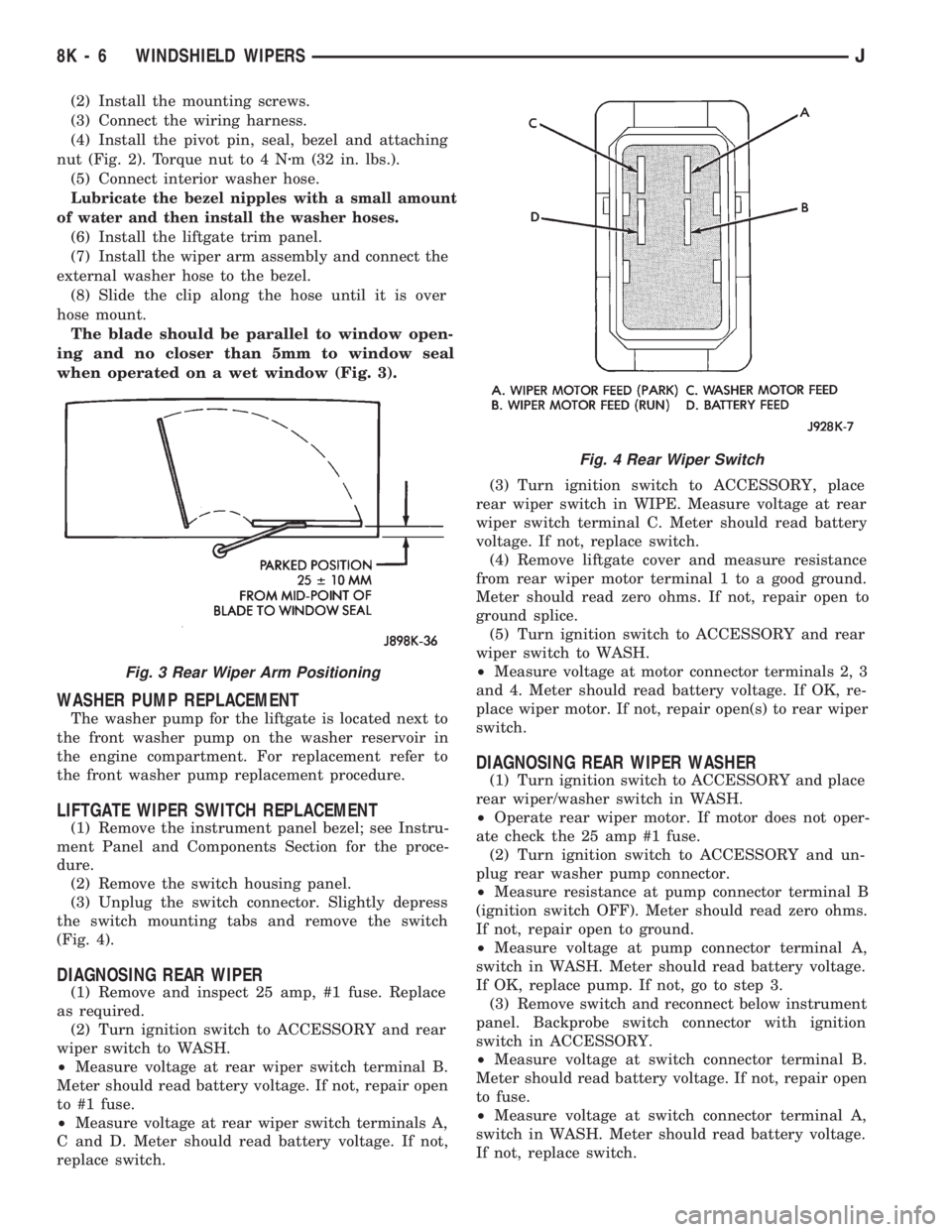
(2) Install the mounting screws.
(3) Connect the wiring harness.
(4) Install the pivot pin, seal, bezel and attaching
nut (Fig. 2). Torque nut to 4 Nzm (32 in. lbs.).
(5) Connect interior washer hose.
Lubricate the bezel nipples with a small amount
of water and then install the washer hoses.
(6) Install the liftgate trim panel.
(7) Install the wiper arm assembly and connect the
external washer hose to the bezel.
(8) Slide the clip along the hose until it is over
hose mount.
The blade should be parallel to window open-
ing and no closer than 5mm to window seal
when operated on a wet window (Fig. 3).
WASHER PUMP REPLACEMENT
The washer pump for the liftgate is located next to
the front washer pump on the washer reservoir in
the engine compartment. For replacement refer to
the front washer pump replacement procedure.
LIFTGATE WIPER SWITCH REPLACEMENT
(1) Remove the instrument panel bezel; see Instru-
ment Panel and Components Section for the proce-
dure.
(2) Remove the switch housing panel.
(3) Unplug the switch connector. Slightly depress
the switch mounting tabs and remove the switch
(Fig. 4).
DIAGNOSING REAR WIPER
(1) Remove and inspect 25 amp, #1 fuse. Replace
as required.
(2) Turn ignition switch to ACCESSORY and rear
wiper switch to WASH.
²Measure voltage at rear wiper switch terminal B.
Meter should read battery voltage. If not, repair open
to #1 fuse.
²Measure voltage at rear wiper switch terminals A,
C and D. Meter should read battery voltage. If not,
replace switch.(3) Turn ignition switch to ACCESSORY, place
rear wiper switch in WIPE. Measure voltage at rear
wiper switch terminal C. Meter should read battery
voltage. If not, replace switch.
(4) Remove liftgate cover and measure resistance
from rear wiper motor terminal 1 to a good ground.
Meter should read zero ohms. If not, repair open to
ground splice.
(5) Turn ignition switch to ACCESSORY and rear
wiper switch to WASH.
²Measure voltage at motor connector terminals 2, 3
and 4. Meter should read battery voltage. If OK, re-
place wiper motor. If not, repair open(s) to rear wiper
switch.
DIAGNOSING REAR WIPER WASHER
(1) Turn ignition switch to ACCESSORY and place
rear wiper/washer switch in WASH.
²Operate rear wiper motor. If motor does not oper-
ate check the 25 amp #1 fuse.
(2) Turn ignition switch to ACCESSORY and un-
plug rear washer pump connector.
²Measure resistance at pump connector terminal B
(ignition switch OFF). Meter should read zero ohms.
If not, repair open to ground.
²Measure voltage at pump connector terminal A,
switch in WASH. Meter should read battery voltage.
If OK, replace pump. If not, go to step 3.
(3) Remove switch and reconnect below instrument
panel. Backprobe switch connector with ignition
switch in ACCESSORY.
²Measure voltage at switch connector terminal B.
Meter should read battery voltage. If not, repair open
to fuse.
²Measure voltage at switch connector terminal A,
switch in WASH. Meter should read battery voltage.
If not, replace switch.
Fig. 3 Rear Wiper Arm Positioning
Fig. 4 Rear Wiper Switch
8K - 6 WINDSHIELD WIPERSJ
Page 420 of 1784
REAR WASHER PUMP REPLACEMENT
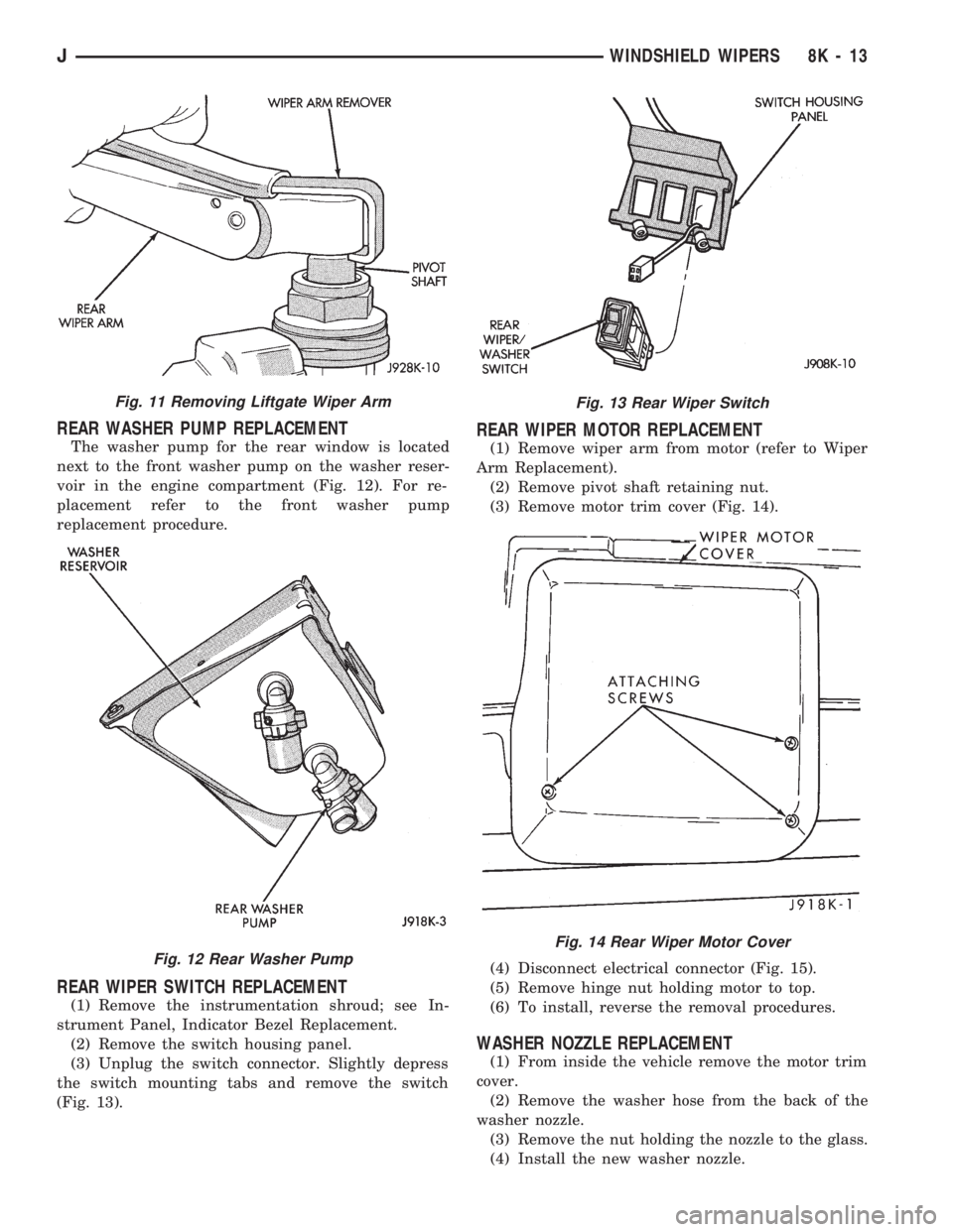
The washer pump for the rear window is located
next to the front washer pump on the washer reser-
voir in the engine compartment (Fig. 12). For re-
placement refer to the front washer pump
replacement procedure.
REAR WIPER SWITCH REPLACEMENT
(1) Remove the instrumentation shroud; see In-
strument Panel, Indicator Bezel Replacement.
(2) Remove the switch housing panel.
(3) Unplug the switch connector. Slightly depress
the switch mounting tabs and remove the switch
(Fig. 13).
REAR WIPER MOTOR REPLACEMENT
(1) Remove wiper arm from motor (refer to Wiper
Arm Replacement).
(2) Remove pivot shaft retaining nut.
(3) Remove motor trim cover (Fig. 14).
(4) Disconnect electrical connector (Fig. 15).
(5) Remove hinge nut holding motor to top.
(6) To install, reverse the removal procedures.
WASHER NOZZLE REPLACEMENT
(1) From inside the vehicle remove the motor trim
cover.
(2) Remove the washer hose from the back of the
washer nozzle.
(3) Remove the nut holding the nozzle to the glass.
(4) Install the new washer nozzle.
Fig. 11 Removing Liftgate Wiper Arm
Fig. 12 Rear Washer Pump
Fig. 13 Rear Wiper Switch
Fig. 14 Rear Wiper Motor Cover
JWINDSHIELD WIPERS 8K - 13
Page 428 of 1784
LAMPS
CONTENTS
page page
EXTERIOR LAMPS....................... 1
INTERIOR LAMPS...................... 19SPECIFICATIONS....................... 23
EXTERIOR LAMPS
INDEX
page page
Back-up/Rear Turn Signal/Tail Lamp Bulb
Replacement........................... 9
Center High Mounted Stop Lamp (CHMSL)ÐXJ . 10
Center High Mounted Stop Lamp (CHMSL)ÐYJ . 11
Daytime Running Lights (Canada Only)........ 16
DRL Module Replacement.................. 16
Fog Lamp Beam Adjustment................ 12
Fog Lamp Bulb/Element Replacement......... 13
Fog Lamp Replacement................... 15
Fog Lamp Service Information............... 12
Fog Lamp Switch Replacement.............. 14
Fog Lamp Trouble Diagnosis................ 12
Front Park/Turn Signal Lamp Bulb Replacement . . 8
Headlamp Beam Adjustment................. 3
Headlamp Bulb Replacement................ 3
Headlamp Delay Function Trouble DiagnosisÐXJ
Vehicles.............................. 16Headlamp Delay Module ReplacementÐXJ
Vehicles.............................. 16
Headlamp Dimmer Switch Replacement........ 6
Headlamp Switch Replacement............... 4
Headlamp Trouble DiagnosisÐXJ Vehicles...... 1
Headlamp Trouble DiagnosisÐYJ Vehicles...... 2
License Plate Lamp....................... 10
Sentinel Headlamp Delay ModuleÐXJ Vehicles . . 15
Service Information........................ 1
Side Marker Lamp Bulb Replacement.......... 7
Switch Tests............................. 2
Underhood Lamp Bulb Replacement.......... 18
Underhood Lamp Replacement.............. 18
Underhood Lamp Service Information......... 17
SERVICE INFORMATION
Exterior lamp circuits are comprised of the head-
lamp circuit, fog lamp circuit, and tail/side marker/
park lamp circuit. Battery voltage is controlled by
both the headlamp ON/OFF switch and headlamp
dimmer switch.
The dimmer switch functions as a fog lamp switch.
Voltage is applied to the fog lamp switch only when
the dimmer switch is in the low beam position.
HEADLAMP TROUBLE DIAGNOSISÐXJ VEHICLES
LOW AND HIGH BEAM INOPERATIVE BOTH
HEADLAMPS
(1) Place the headlamp switch in the ON position.
(2) Test the 40 amp fuse for continuity. If bad, re-
place fuse.
(3) Insert the test probe into terminal 5 of the
front lamp wire harness connector. Measure the re-
sistance from terminal 5 to body ground. The ohm-
meter should indicate zero ohms. If not OK, repair
the open circuit in the harness to body ground.(4) Disconnect the front lamp wire connector. Mea-
sure resistance between connector terminals 5 and 2.
Next measure between terminal 5 and 7. The ohm-
meter should indicate zero ohms for both measure-
ments. If not OK, replace the headlamp bulbs.
(5) Measure the voltage between the dimmer
switch wire connector terminal 2 and body ground.
The voltmeter should indicate battery voltage. If not
OK, continue with the next step.
The dimmer switch is integral with the turn
signal and is located on the steering column.
The dimmer switch switches the headlamp beam
when the turn signal lever is pulled rearward.
(6) Disconnect the dimmer switch wire connector
and place the headlamp switch in the OFF position.
Measure the resistance from terminal 2 to vehicle
body ground. The ohmmeter should indicate infinite
resistance. If OK, replace the headlamp switch and
continue with the next step. If not OK, repair the
short circuit in the wire harness that leads to termi-
nal 2.
JLAMPS 8L - 1
Page 446 of 1784
INTERIOR LAMPS
INDEX
page page
Dome Lamp Replacement.................. 20
Dome/Courtesy Lamp Service Information...... 19
Dome/Courtesy Lamp Trouble Diagnosis....... 19
Hardtop Dome/Cargo Lamp Bulb ReplacementÐYJ
Vehicles.............................. 20Illuminated Entry System Service Information . . . 20
Illuminated Entry System Trouble Diagnosis.... 21
Lighted Vanity Mirror...................... 19
Lighted Vanity Mirror Trouble Diagnosis....... 19
Overhead ConsoleÐXJ Vehicles............. 20
DOME/COURTESY LAMP SERVICE INFORMATION
XJ VEHICLES
Voltage is applied at all times via the dome lamp
fuse to each of the interior lamp bulbs. The interior
lamp bulbs illuminate when they are connected to
body ground via the switch:
²headlamp switch,
²glove box switch,
²door pillar switch, and
²liftgate switch (if the cargo lamp is ON.)
If equipped with Security Alarm Module, refer to
Group 8QÐVehicle Theft Security System.
YJ VEHICLES
The dome/cargo and courtesy lamps are controlled
via ON/OFF switches. The ON/OFF switches are in
the lamp ground circuits. Voltage via the dome/cour-
tesy lamp fuse is applied directly to the lamp bulbs.
When either door is opened, the door pillar switch
contacts close and provide a direct path to vehicle
body ground.
The cargo/cargo and courtesy lamps can also be
turned on via the interior lamp illumination rheo-
stat.
DOME/COURTESY LAMP TROUBLE DIAGNOSIS
ALL LAMPS INOPERATIVE
(1) Rotate the headlamp switch rheostat clockwise.
The lamps should light. If not OK, remove, inspect
and test the dome lamp fuse. Replace if bad.
(2) If the fuse is OK, repair the open circuit in the
wire harness to vehicle body ground.
ONE LAMP INOPERATIVE
(1) Measure the resistance across the bulb holder
terminals. The ohmmeter should indicate zero ohms.
If not, replace the bulb.
(2) Measure the voltage between the voltage side
of the bulb holder and vehicle body ground. The volt-
meter should indicate battery voltage. If not, repair
the open circuit in the wire harness to the splice.
LAMPS INOPERATIVE WITH ONE OR MORE
DOORS OPENED
(1) Remove the inoperative switch from the door
pillar and connect the switch wire directly to ground.
The lamp should light.
(2) If not, check for an open circuit in black
(ground) wire. Repair as necessary. If lamps still do
not light, replace the switch.
LIGHTED VANITY MIRROR
SERVICE INFORMATIONÐXJ VEHICLES
Both the driver and the front passenger sunvisor
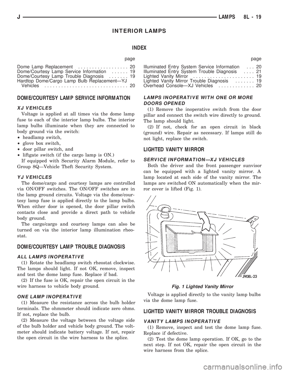
can be equipped with a lighted vanity mirror. A
lamp located at each side of the vanity mirror. The
lamps are switched ON automatically when the mir-
ror cover is lifted (Fig. 1).
Voltage is applied directly to the vanity lamp bulbs
via the dome lamp fuse.
LIGHTED VANITY MIRROR TROUBLE DIAGNOSIS
VANITY LAMPS INOPERATIVE
(1) Remove, inspect and test the dome lamp fuse.
Replace if defective.
(2) Test the dome lamp operation. If OK, go to the
next step. If not OK, repair the open circuit in the
wire harness from the splice.
Fig. 1 Lighted Vanity Mirror
JLAMPS 8L - 19