1994 JEEP CHEROKEE front light
[x] Cancel search: front lightPage 466 of 1784
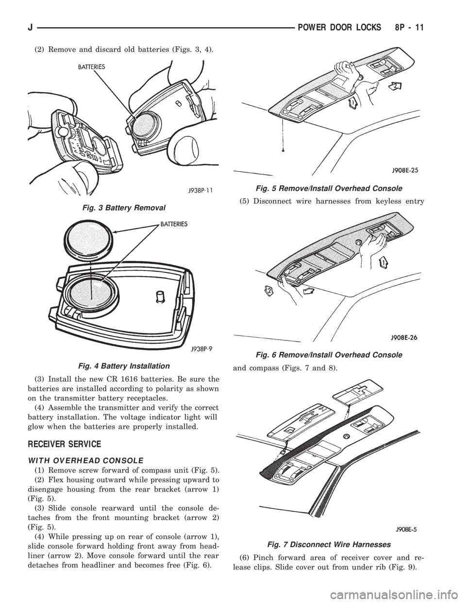
(2) Remove and discard old batteries (Figs. 3, 4).
(3) Install the new CR 1616 batteries. Be sure the
batteries are installed according to polarity as shown
on the transmitter battery receptacles.
(4) Assemble the transmitter and verify the correct
battery installation. The voltage indicator light will
glow when the batteries are properly installed.
RECEIVER SERVICE
WITH OVERHEAD CONSOLE
(1) Remove screw forward of compass unit (Fig. 5).
(2) Flex housing outward while pressing upward to
disengage housing from the rear bracket (arrow 1)
(Fig. 5).
(3) Slide console rearward until the console de-
taches from the front mounting bracket (arrow 2)
(Fig. 5).
(4) While pressing up on rear of console (arrow 1),
slide console forward holding front away from head-
liner (arrow 2). Move console forward until the rear
detaches from headliner and becomes free (Fig. 6).(5) Disconnect wire harnesses from keyless entry
and compass (Figs. 7 and 8).
(6) Pinch forward area of receiver cover and re-
lease clips. Slide cover out from under rib (Fig. 9).
Fig. 3 Battery Removal
Fig. 4 Battery Installation
Fig. 5 Remove/Install Overhead Console
Fig. 6 Remove/Install Overhead Console
Fig. 7 Disconnect Wire Harnesses
JPOWER DOOR LOCKS 8P - 11
Page 468 of 1784
POWER SEATS
CONTENTS
page page
DIAGNOSIS............................. 1
GENERAL.............................. 1POWER SEAT MOTOR REPLACEMENT....... 2
SWITCH TESTING....................... 2
GENERAL
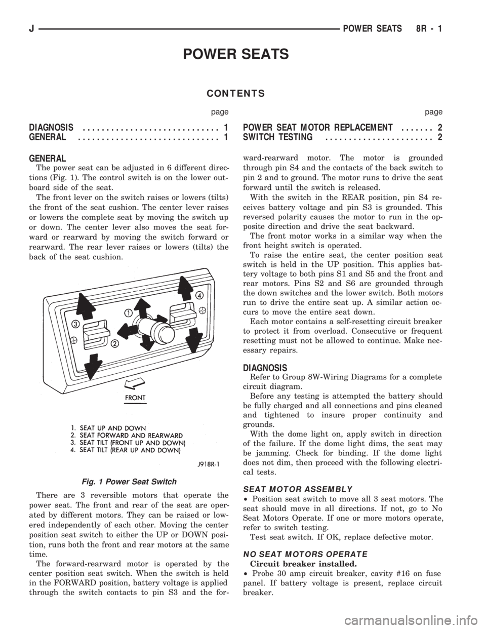
The power seat can be adjusted in 6 different direc-
tions (Fig. 1). The control switch is on the lower out-
board side of the seat.
The front lever on the switch raises or lowers (tilts)
the front of the seat cushion. The center lever raises
or lowers the complete seat by moving the switch up
or down. The center lever also moves the seat for-
ward or rearward by moving the switch forward or
rearward. The rear lever raises or lowers (tilts) the
back of the seat cushion.
There are 3 reversible motors that operate the
power seat. The front and rear of the seat are oper-
ated by different motors. They can be raised or low-
ered independently of each other. Moving the center
position seat switch to either the UP or DOWN posi-
tion, runs both the front and rear motors at the same
time.
The forward-rearward motor is operated by the
center position seat switch. When the switch is held
in the FORWARD position, battery voltage is applied
through the switch contacts to pin S3 and the for-ward-rearward motor. The motor is grounded
through pin S4 and the contacts of the back switch to
pin 2 and to ground. The motor runs to drive the seat
forward until the switch is released.
With the switch in the REAR position, pin S4 re-
ceives battery voltage and pin S3 is grounded. This
reversed polarity causes the motor to run in the op-
posite direction and drive the seat backward.
The front motor works in a similar way when the
front height switch is operated.
To raise the entire seat, the center position seat
switch is held in the UP position. This applies bat-
tery voltage to both pins S1 and S5 and the front and
rear motors. Pins S2 and S6 are grounded through
the down switches and the lower switch. Both motors
run to drive the entire seat up. A similar action oc-
curs to move the entire seat down.
Each motor contains a self-resetting circuit breaker
to protect it from overload. Consecutive or frequent
resetting must not be allowed to continue. Make nec-
essary repairs.
DIAGNOSIS
Refer to Group 8W-Wiring Diagrams for a complete
circuit diagram.
Before any testing is attempted the battery should
be fully charged and all connections and pins cleaned
and tightened to insure proper continuity and
grounds.
With the dome light on, apply switch in direction
of the failure. If the dome light dims, the seat may
be jamming. Check for binding. If the dome light
does not dim, then proceed with the following electri-
cal tests.
SEAT MOTOR ASSEMBLY
²Position seat switch to move all 3 seat motors. The
seat should move in all directions. If not, go to No
Seat Motors Operate. If one or more motors operate,
refer to switch testing.
Test seat switch. If OK, replace defective motor.
NO SEAT MOTORS OPERATE
Circuit breaker installed.
²Probe 30 amp circuit breaker, cavity #16 on fuse
panel. If battery voltage is present, replace circuit
breaker.
Fig. 1 Power Seat Switch
JPOWER SEATS 8R - 1
Page 472 of 1784
POWER WINDOWS
CONTENTS
page page
DESCRIPTION........................... 1
DIAGNOSIS (Figs. 1 and 2)............... 1SWITCH TESTING....................... 5
WINDOW REGULATOR REPLACEMENT...... 9
DESCRIPTION
All XJ vehicles, equipped with power windows,
have a cable driven window regulator system. A per-
manent magnet motor moves each power window.
Each motor raises or lowers the glass when voltage
is supplied to the motor. The direction the motor
turns depends on the polarity of the supply voltage.
The control switches control the supply voltage polar-
ity.
With the ignition switch in the ON position voltage
from the 60 amp fuse in the Power Distribution Cen-
ter is applied through the power window circuit
breaker. Power then goes to the master switch termi-
nal BY and to the passenger's window switches.
When the driver's window switch is moved UP, the
contacts close a current path to:
²terminal DV
²driver's side front window motor
²terminal CV
²the DOWN contact of the driver's side front win-
dow to ground.
The motor then moves the glass up.
Current flows in a similar way when the UP con-
tact in one of the passenger's window switches is
closed. Current flow through the passenger's window
motors must go through the driver's and the passen-
ger's window switches before it reaches ground.
Each motor is protected by a built-in circuit
breaker. If a window switch is held on too long with
the window obstructed or after the window is fully
up or down, the circuit breaker opens the circuit. The
circuit breaker resets automatically as it cools. Do
not allow frequent or consecutive resetting of the cir-
cuit breaker to continue.
DIAGNOSIS (Figs. 1 and 2)
For information concerning wiring or connectors,
refer to Group 8W - Wiring Diagrams.
NO WINDOWS OPERATE
²Measure voltage at power window feed connector
at fuse panel. Meter should read battery voltage. If
not, replace 60 amp fuse in Power Distribution Cen-
ter.
²Turn ignition switch to OFF and measure resis-
tance from side of cigar lighter socket to ground.
Meter should read zero ohms. If not, repair open to
ground.
²Remove master door lock/power window switch as-
sembly mounting screws. Measure resistance at BLK
wire (terminal DX) at driver's side switch. Meter
should read zero ohms. If not, repair open to ground
splice of instrument panel harness.
²Turn ignition switch to ON and measure voltage
at terminal BY at driver's side switch. Meter should
read battery voltage. If not, repair open to circuit
breaker.
²Operate window switch. If the windows move up
and down go to Switch Testing.
²Perform Switch Test Driver's Door. If switch
passes test, replace defective motors.
ONE WINDOW OPERATES
Remove door panel of inoperative window,
probe harness side of unplugged motor connec-
tor.
²Measure voltage at terminal A of connector, hold-
ing switch in the DOWN position. Meter should read
battery voltage. If not, repair open back to master
switch. If additional switch is in circuit (not driver's
side motor), refer to Switch Testing.
²Measure resistance at terminal B of connector,
holding switch in the DOWN position. Meter should
read zero ohms. Caution, maintain DOWN position
while meter lead is attached. If not, repair open back
to master switch. If additional switch is in circuit
(not driver's side motor), refer to Switch Testing. If
both tests are OK, replace regulator.
JPOWER WINDOWS 8S - 1
Page 566 of 1784
WIRING DIAGRAMS YJ
ALPHABETICAL INDEX
Wiring Diagram Name Sheet Number
ABS Accelerator Sensor........................59
ABS Control Module.....................57, 58, 59
ABS Control Module Connector...................60
ABS Motor Pump Relay........................57
ABS Power Relay............................57
A/C Blower Switch............................50
A/C Compressor.............................49
A/C Low Pressure Switch.......................49
A/C Relay.................................49
A/C Thermostat..............................50
Accessory Illumination.........................32
Air Conditioning System (4.0L).................49, 50
A/C Blower Switch..........................50
A/C Compressor............................49
A/C Low Pressure Switch.....................49
A/C Relay................................49
A/C Thermostat............................50
Field Jumper..............................50
Powertrain Control Module.....................49
Anti-Lock Brake System (TEVES).............57, 58, 59
ABS Accelerator Sensor.......................59
ABS Control Module....................57, 58, 59
ABS Motor Pump Relay.......................57
ABS Power Relay...........................57
Brake Pedal Travel Sensor.....................57
Data Link Connector.........................57
Diode..................................58
Hydraulic Actuation Unit......................58
Left Front Wheel Sensor......................59
Left Rear Wheel Sensor.......................59
Power Distribution Center.....................57
Pump Motor..............................57
Pump Motor Sensor.........................57
Right Front Wheel Sensor.....................59
Right Rear Wheel Sensor......................59
Automatic Shut-Down Relay...................11, 17
Back-Up Lamps...........................51, 52
Back-Up Lamp Switch..........................7
Battery................................1,3,5
Blower Motor...............................47
Blower Resistor.............................47
Blower Switch..............................47
Body Harness Connector........................36
Brake Pedal Travel Sensor.......................57
Brake Warning Switch..........................9
Bulkhead Connector........................65, 66
Buzzer Module..............................36
Camshaft Position Sensor....................12, 18
Center High Mounted Stop Lamp..................52
Charging System 2.5L Engine...................3,4
Battery..................................3
Generator.................................3
Power Distribution Center......................4Wiring Diagram Name Sheet Number
Charging System 4.0L Engine...................5,6
Battery..................................5
Generator.................................5
Power Distribution Center......................6
Cigar Lighter...............................24
Circuit Breakers
Headlamp Switch.........................1,29
#11 (W/Wiper).....................2,10,38,39
Clock....................................45
Cluster Connector............................41
Crankshaft Position Sensor...................12, 18
Data Link Connector.....................13, 19, 57
Daytime Running Lamp Module...................28
Dimmer Switch............................1,29
Dome and Courtesy Lamps......................35
Dome Lamp..............................35
Left Courtesy Lamp.........................35
Left Front Door Jamb Switch...................35
Right Courtesy Lamp........................35
Right Front Door Jamb Switch..................35
Dome Lamp................................35
Electrically Tuned Radio with Clock.................45
Electrical Schematic of Cluster....................42
Electrical Schematic of Gauge Package..............44
Electronic Speedometer.........................42
Electronic Tachometer..........................42
Engine Coolant Temp Gauge.....................44
Engine Coolant Temperature Sensor..............15, 21
Engine Oil Pressure and Temperature System..........23
Engine Coolant Temperature Sending Unit...........23
Engine Oil Pressure Sending Unit................23
Engine Oil Pressure Gauge......................44
Engine Starter System........................2,7
Back-Up Lamp Switch........................7
Engine Starter Motor.........................7
Engine Starter Relay..........................7
Park/Neutral Position Switch....................7
Engine Wiring Connector (16 Way).................69
4-WD Command Trac Switch......................8
Field Jumper...............................50
Fog Lamp Relays............................30
Fog Lamp Switch............................30
Front End Lighting.........................25, 26
Left Fog Lamp.............................25
Left Headlamp.............................25
Left Park and Turn Signal Lamp.................25
Left Side Marker Lamp.......................25
Right Fog Lamp............................26
Right Headlamp............................26
Right Park and Turn Signal Lamp................26
Right Side Marker Lamp......................26
Front End Lighting (Canada)...................27, 28
Daytime Running Lamp Module.................28
JWIRING DIAGRAMS 8W - 73
Page 568 of 1784
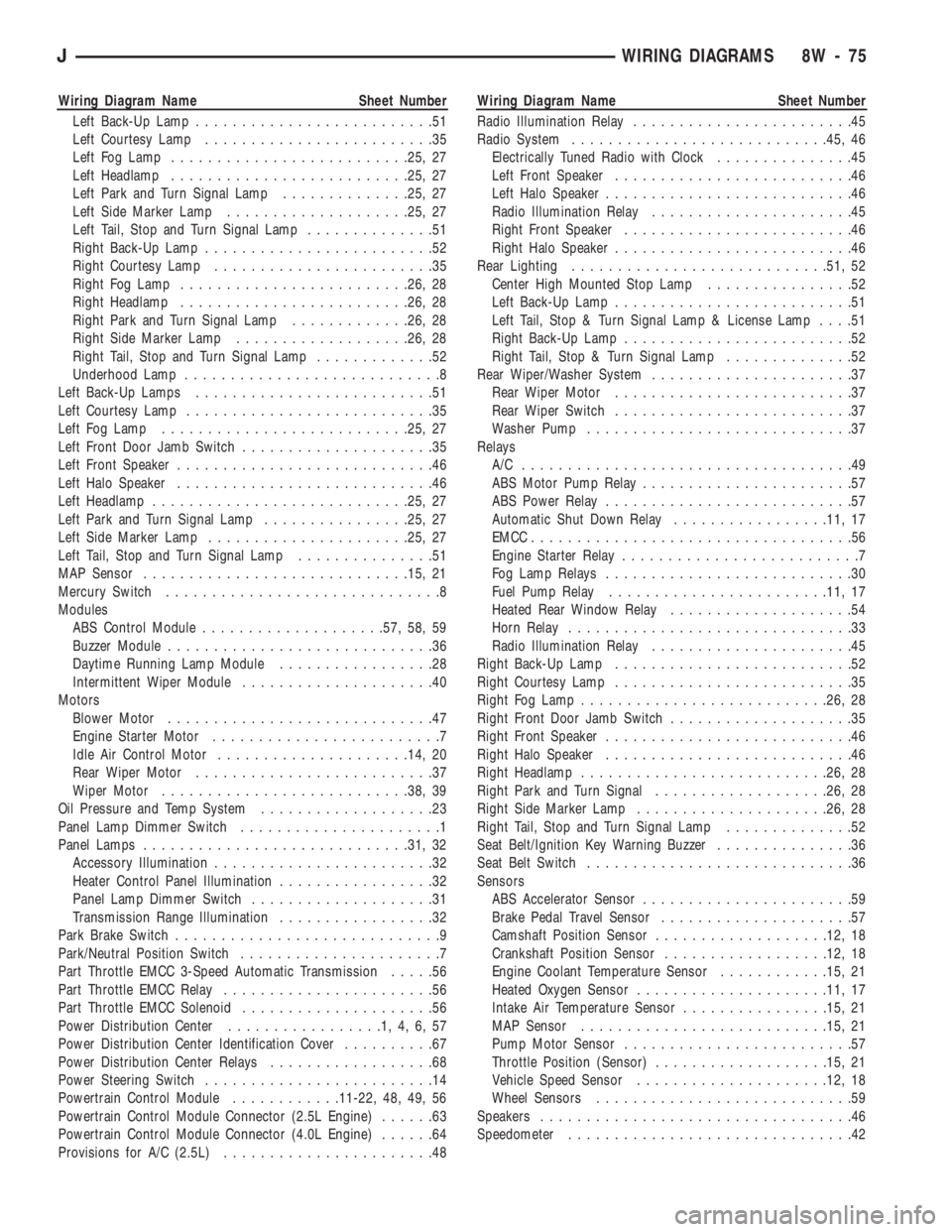
Wiring Diagram Name Sheet Number
Left Back-Up Lamp..........................51
Left Courtesy Lamp.........................35
Left Fog Lamp..........................25, 27
Left Headlamp..........................25, 27
Left Park and Turn Signal Lamp..............25, 27
Left Side Marker Lamp....................25, 27
Left Tail, Stop and Turn Signal Lamp..............51
Right Back-Up Lamp.........................52
Right Courtesy Lamp........................35
Right Fog Lamp.........................26, 28
Right Headlamp.........................26, 28
Right Park and Turn Signal Lamp.............26, 28
Right Side Marker Lamp...................26, 28
Right Tail, Stop and Turn Signal Lamp.............52
Underhood Lamp............................8
Left Back-Up Lamps..........................51
Left Courtesy Lamp...........................35
Left Fog Lamp...........................25, 27
Left Front Door Jamb Switch.....................35
Left Front Speaker............................46
Left Halo Speaker............................46
Left Headlamp............................25, 27
Left Park and Turn Signal Lamp................25, 27
Left Side Marker Lamp......................25, 27
Left Tail, Stop and Turn Signal Lamp...............51
MAP Sensor.............................15, 21
Mercury Switch..............................8
Modules
ABS Control Module....................57, 58, 59
Buzzer Module.............................36
Daytime Running Lamp Module.................28
Intermittent Wiper Module.....................40
Motors
Blower Motor.............................47
Engine Starter Motor.........................7
Idle Air Control Motor.....................14, 20
Rear Wiper Motor..........................37
Wiper Motor...........................38, 39
Oil Pressure and Temp System...................23
Panel Lamp Dimmer Switch......................1
Panel Lamps.............................31, 32
Accessory Illumination........................32
Heater Control Panel Illumination.................32
Panel Lamp Dimmer Switch....................31
Transmission Range Illumination.................32
Park Brake Switch.............................9
Park/Neutral Position Switch......................7
Part Throttle EMCC 3-Speed Automatic Transmission.....56
Part Throttle EMCC Relay.......................56
Part Throttle EMCC Solenoid.....................56
Power Distribution Center.................1,4,6,57
Power Distribution Center Identification Cover..........67
Power Distribution Center Relays..................68
Power Steering Switch.........................14
Powertrain Control Module............11-22, 48, 49, 56
Powertrain Control Module Connector (2.5L Engine)......63
Powertrain Control Module Connector (4.0L Engine)......64
Provisions for A/C (2.5L).......................48Wiring Diagram Name Sheet Number
Radio Illumination Relay........................45
Radio System............................45, 46
Electrically Tuned Radio with Clock...............45
Left Front Speaker..........................46
Left Halo Speaker...........................46
Radio Illumination Relay......................45
Right Front Speaker.........................46
Right Halo Speaker..........................46
Rear Lighting............................51, 52
Center High Mounted Stop Lamp................52
Left Back-Up Lamp..........................51
Left Tail, Stop & Turn Signal Lamp & License Lamp....51
Right Back-Up Lamp.........................52
Right Tail, Stop & Turn Signal Lamp..............52
Rear Wiper/Washer System......................37
Rear Wiper Motor..........................37
Rear Wiper Switch..........................37
Washer Pump.............................37
Relays
A/C ....................................49
ABS Motor Pump Relay.......................57
ABS Power Relay...........................57
Automatic Shut Down Relay.................11, 17
EMCC...................................56
Engine Starter Relay..........................7
Fog Lamp Relays...........................30
Fuel Pump Relay........................11, 17
Heated Rear Window Relay....................54
Horn Relay...............................33
Radio Illumination Relay......................45
Right Back-Up Lamp..........................52
Right Courtesy Lamp..........................35
Right Fog Lamp...........................26, 28
Right Front Door Jamb Switch....................35
Right Front Speaker...........................46
Right Halo Speaker...........................46
Right Headlamp...........................26, 28
Right Park and Turn Signal...................26, 28
Right Side Marker Lamp.....................26, 28
Right Tail, Stop and Turn Signal Lamp..............52
Seat Belt/Ignition Key Warning Buzzer...............36
Seat Belt Switch.............................36
Sensors
ABS Accelerator Sensor.......................59
Brake Pedal Travel Sensor.....................57
Camshaft Position Sensor...................12, 18
Crankshaft Position Sensor..................12, 18
Engine Coolant Temperature Sensor............15, 21
Heated Oxygen Sensor.....................11, 17
Intake Air Temperature Sensor................15, 21
MAP Sensor...........................15, 21
Pump Motor Sensor.........................57
Throttle Position (Sensor)...................15, 21
Vehicle Speed Sensor.....................12, 18
Wheel Sensors............................59
Speakers..................................46
Speedometer...............................42
JWIRING DIAGRAMS 8W - 75
Page 642 of 1784
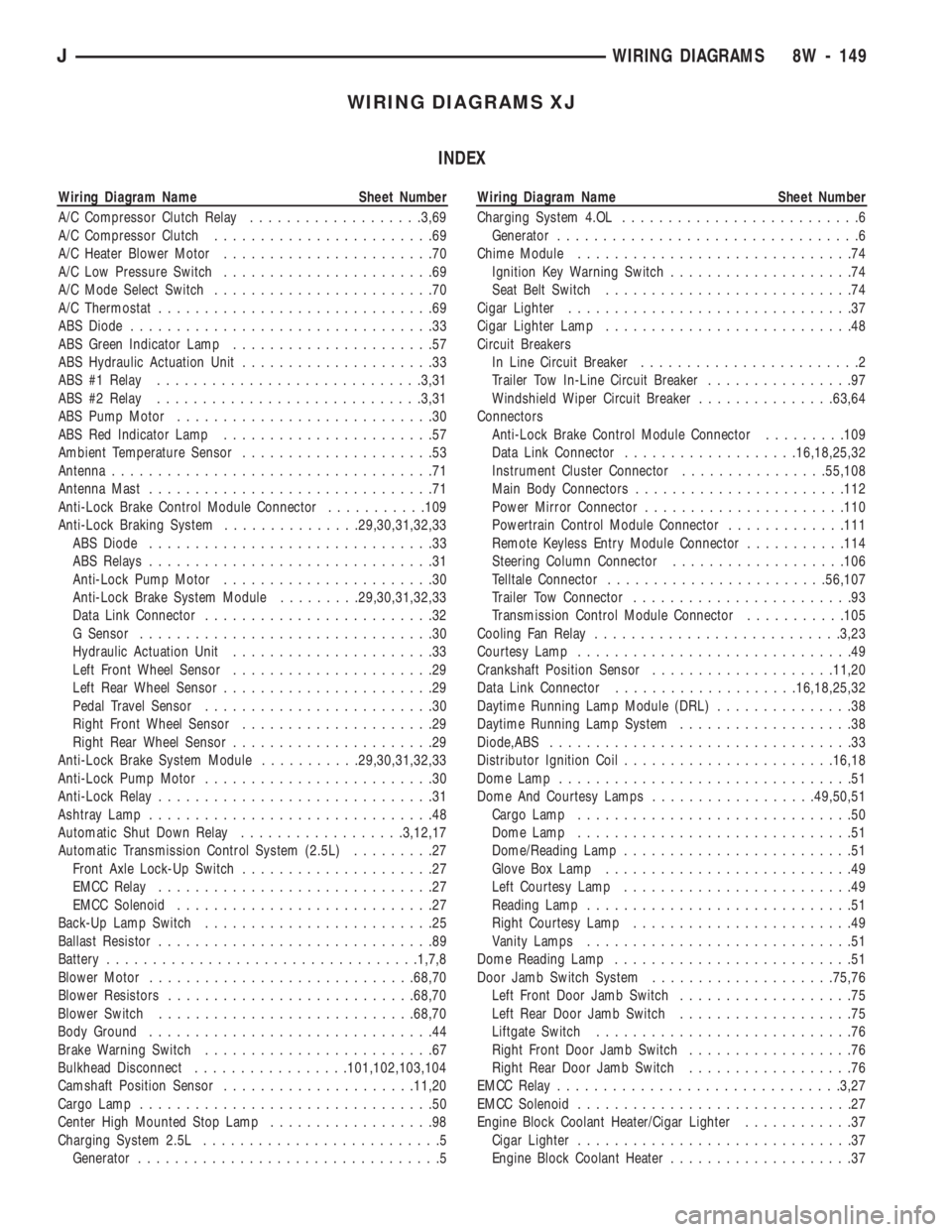
WIRING DIAGRAMS XJ
INDEX
Wiring Diagram Name Sheet Number
A/C Compressor Clutch Relay...................3,69
A/C Compressor Clutch........................69
A/C Heater Blower Motor.......................70
A/C Low Pressure Switch.......................69
A/C Mode Select Switch........................70
A/C Thermostat..............................69
ABS Diode.................................33
ABS Green Indicator Lamp......................57
ABS Hydraulic Actuation Unit.....................33
ABS #1 Relay.............................3,31
ABS #2 Relay.............................3,31
ABS Pump Motor............................30
ABS Red Indicator Lamp.......................57
Ambient Temperature Sensor.....................53
Antenna...................................71
Antenna Mast...............................71
Anti-Lock Brake Control Module Connector...........109
Anti-Lock Braking System...............29,30,31,32,33
ABS Diode...............................33
ABS Relays...............................31
Anti-Lock Pump Motor.......................30
Anti-Lock Brake System Module.........29,30,31,32,33
Data Link Connector.........................32
G Sensor................................30
Hydraulic Actuation Unit......................33
Left Front Wheel Sensor......................29
Left Rear Wheel Sensor.......................29
Pedal Travel Sensor.........................30
Right Front Wheel Sensor.....................29
Right Rear Wheel Sensor......................29
Anti-Lock Brake System Module...........29,30,31,32,33
Anti-Lock Pump Motor.........................30
Anti-Lock Relay..............................31
Ashtray Lamp...............................48
Automatic Shut Down Relay..................3,12,17
Automatic Transmission Control System (2.5L).........27
Front Axle Lock-Up Switch.....................27
EMCC Relay..............................27
EMCC Solenoid............................27
Back-Up Lamp Switch.........................25
Ballast Resistor..............................89
Battery..................................1,7,8
Blower Motor.............................68,70
Blower Resistors...........................68,70
Blower Switch............................68,70
Body Ground...............................44
Brake Warning Switch.........................67
Bulkhead Disconnect.................101,102,103,104
Camshaft Position Sensor.....................11,20
Cargo Lamp................................50
Center High Mounted Stop Lamp..................98
Charging System 2.5L..........................5
Generator.................................5Wiring Diagram Name Sheet Number
Charging System 4.OL..........................6
Generator.................................6
Chime Module..............................74
Ignition Key Warning Switch....................74
Seat Belt Switch...........................74
Cigar Lighter...............................37
Cigar Lighter Lamp...........................48
Circuit Breakers
In Line Circuit Breaker........................2
Trailer Tow In-Line Circuit Breaker................97
Windshield Wiper Circuit Breaker...............63,64
Connectors
Anti-Lock Brake Control Module Connector.........109
Data Link Connector...................16,18,25,32
Instrument Cluster Connector................55,108
Main Body Connectors.......................112
Power Mirror Connector......................110
Powertrain Control Module Connector.............111
Remote Keyless Entry Module Connector...........114
Steering Column Connector...................106
Telltale Connector........................56,107
Trailer Tow Connector........................93
Transmission Control Module Connector...........105
Cooling Fan Relay...........................3,23
Courtesy Lamp..............................49
Crankshaft Position Sensor....................11,20
Data Link Connector....................16,18,25,32
Daytime Running Lamp Module (DRL)...............38
Daytime Running Lamp System...................38
Diode,ABS.................................33
Distributor Ignition Coil.......................16,18
Dome Lamp................................51
Dome And Courtesy Lamps..................49,50,51
Cargo Lamp..............................50
Dome Lamp..............................51
Dome/Reading Lamp.........................51
Glove Box Lamp...........................49
Left Courtesy Lamp.........................49
Reading Lamp.............................51
Right Courtesy Lamp........................49
Vanity Lamps.............................51
Dome Reading Lamp..........................51
Door Jamb Switch System....................75,76
Left Front Door Jamb Switch...................75
Left Rear Door Jamb Switch...................75
Liftgate Switch............................76
Right Front Door Jamb Switch..................76
Right Rear Door Jamb Switch..................76
EMCC Relay...............................3,27
EMCC Solenoid..............................27
Engine Block Coolant Heater/Cigar Lighter............37
Cigar Lighter..............................37
Engine Block Coolant Heater....................37
JWIRING DIAGRAMS 8W - 149
Page 643 of 1784
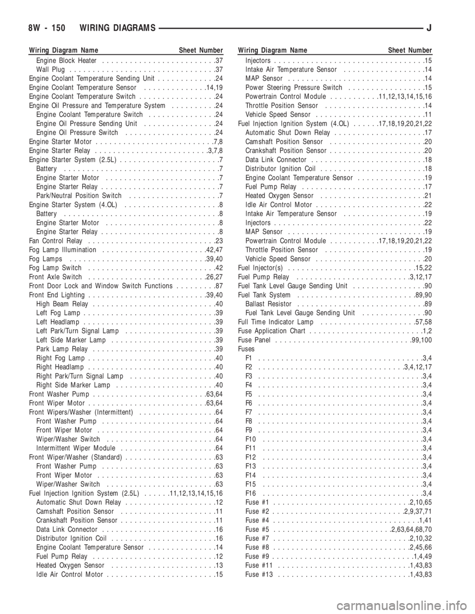
Wiring Diagram Name Sheet Number
Engine Block Heater.........................37
Wall Plug................................37
Engine Coolant Temperature Sending Unit.............24
Engine Coolant Temperature Sensor..............14,19
Engine Coolant Temperature Switch.................24
Engine Oil Pressure and Temperature System..........24
Engine Coolant Temperature Switch...............24
Engine Oil Pressure Sending Unit................24
Engine Oil Pressure Switch....................24
Engine Starter Motor..........................7,8
Engine Starter Relay.........................3,7,8
Engine Starter System (2.5L)......................7
Battery..................................7
Engine Starter Motor.........................7
Engine Starter Relay..........................7
Park/Neutral Position Switch....................7
Engine Starter System (4.OL).....................8
Battery..................................8
Engine Starter Motor.........................8
Engine Starter Relay..........................8
Fan Control Relay............................23
Fog Lamp Illumination.......................42,47
Fog Lamps..............................39,40
Fog Lamp Switch............................42
Front Axle Switch..........................26,27
Front Door Lock and Window Switch Functions.........87
Front End Lighting..........................39,40
High Beam Relay...........................40
Left Fog Lamp.............................39
Left Headlamp.............................39
Left Park/Turn Signal Lamp....................39
Left Side Marker Lamp.......................39
Park Lamp Relay...........................39
Right Fog Lamp............................40
Right Headlamp............................40
Right Park/Turn Signal Lamp...................40
Right Side Marker Lamp......................40
Front Washer Pump.........................63,64
Front Wiper Motor..........................63,64
Front Wipers/Washer (Intermittent).................64
Front Washer Pump.........................64
Front Wiper Motor..........................64
Wiper/Washer Switch........................64
Intermittent Wiper Module.....................64
Front Wiper/Washer (Standard)....................63
Front Washer Pump.........................63
Front Wiper Motor..........................63
Wiper/Washer Switch........................63
Fuel Injection Ignition System (2.5L)......11,12,13,14,15,16
Automatic Shut Down Relay....................12
Camshaft Position Sensor.....................11
Crankshaft Position Sensor.....................11
Data Link Connector.........................16
Distributor Ignition Coil.......................16
Engine Coolant Temperature Sensor...............14
Fuel Pump Relay...........................12
Heated Oxygen Sensor.......................13
Idle Air Control Motor........................15Wiring Diagram Name Sheet Number
Injectors.................................15
Intake Air Temperature Sensor..................14
MAP Sensor..............................14
Power Steering Pressure Switch.................15
Powertrain Control Module...........11,12,13,14,15,16
Throttle Position Sensor......................14
Vehicle Speed Sensor........................11
Fuel Injection Ignition System (4.OL)......17,18,19,20,21,22
Automatic Shut Down Relay....................17
Camshaft Position Sensor.....................20
Crankshaft Position Sensor.....................20
Data Link Connector.........................18
Distributor Ignition Coil.......................18
Engine Coolant Temperature Sensor...............19
Fuel Pump Relay...........................17
Heated Oxygen Sensor.......................21
Idle Air Control Motor........................22
Intake Air Temperature Sensor..................19
Injectors.................................22
MAP Sensor..............................19
Powertrain Control Module...........17,18,19,20,21,22
Throttle Position Sensor......................19
Vehicle Speed Sensor........................20
Fuel Injector(s)............................15,22
Fuel Pump Relay.........................3,12,17
Fuel Tank Level Gauge Sending Unit................90
Fuel Tank System..........................89,90
Ballast Resistor............................89
Fuel Tank Level Gauge Sending Unit..............90
Full Time Indicator Lamp.....................57,58
Fuse Application Chart.........................1,2
Fuse Panel..............................99,100
Fuses
F1 ....................................3,4
F2 ................................3,4,12,17
F3 ....................................3,4
F4 ....................................3,4
F5 ....................................3,4
F6 ....................................3,4
F7 ....................................3,4
F8 ....................................3,4
F9 ....................................3,4
F10 ...................................3,4
F11 ...................................3,4
F12 ...................................3,4
F13 ...................................3,4
F14 ...................................3,4
F15 ...................................3,4
F16 ...................................3,4
Fuse #1..............................2,10,65
Fuse #2.............................2,9,37,71
Fuse #4................................1,41
Fuse #5..........................2,63,64,68,70
Fuse #7..............................2,10,32
Fuse #8..............................2,45,66
Fuse #9...............................1,4,49
Fuse #11.............................1,43,83
Fuse #13.............................1,43,83
8W - 150 WIRING DIAGRAMSJ
Page 644 of 1784
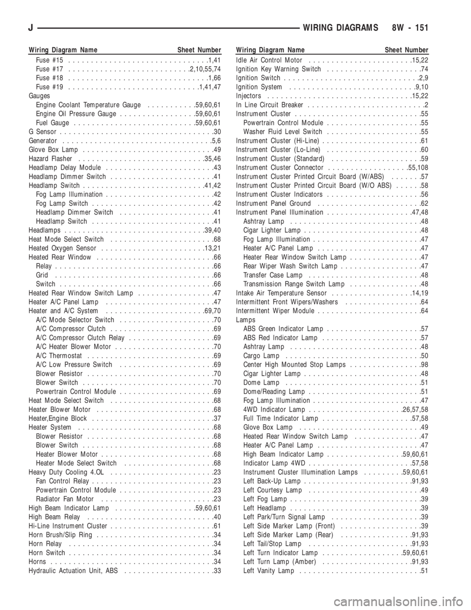
Wiring Diagram Name Sheet Number
Fuse #15...............................1,41
Fuse #17...........................2,10,55,74
Fuse #18...............................1,66
Fuse #19.............................1,41,47
Gauges
Engine Coolant Temperature Gauge...........59,60,61
Engine Oil Pressure Gauge.................59,60,61
Fuel Gauge...........................59,60,61
G Sensor..................................30
Generator.................................5,6
Glove Box Lamp.............................49
Hazard Flasher............................35,46
Headlamp Delay Module........................43
Headlamp Dimmer Switch.......................41
Headlamp Switch...........................41,42
Fog Lamp Illumination........................42
Fog Lamp Switch...........................42
Headlamp Dimmer Switch.....................41
Headlamp Switch...........................41
Headlamps...............................39,40
Heat Mode Select Switch.......................68
Heated Oxygen Sensor.......................13,21
Heated Rear Window..........................66
Relay...................................66
Grid...................................66
Switch..................................66
Heated Rear Window Switch Lamp.................47
Heater A/C Panel Lamp........................47
Heater and A/C System......................69,70
A/C Mode Selector Switch.....................70
A/C Compressor Clutch.......................69
A/C Compressor Clutch Relay...................69
A/C Heater Blower Motor......................70
A/C Thermostat............................69
A/C Low Pressure Switch.....................69
Blower Resistor............................70
Blower Switch.............................70
Powertrain Control Module.....................69
Heat Mode Select Switch.......................68
Heater Blower Motor..........................68
Heater,Engine Block...........................37
Heater System..............................68
Blower Resistor............................68
Blower Switch.............................68
Heater Blower Motor.........................68
Heater Mode Select Switch....................68
Heavy Duty Cooling 4.OL.......................23
Fan Control Relay...........................23
Powertrain Control Module.....................23
Radiator Fan Motor.........................23
High Beam Indicator Lamp..................59,60,61
High Beam Relay............................40
Hi-Line Instrument Cluster.......................61
Horn Brush/Slip Ring..........................34
Horn Relay................................34
Horn Switch................................34
Horns....................................34
Hydraulic Actuation Unit, ABS....................33Wiring Diagram Name Sheet Number
Idle Air Control Motor.......................15,22
Ignition Key Warning Switch.....................74
Ignition Switch..............................2,9
Ignition System............................9,10
Injectors................................15,22
In Line Circuit Breaker..........................2
Instrument Cluster............................55
Powertrain Control Module.....................55
Washer Fluid Level Switch.....................55
Instrument Cluster (Hi-Line)......................61
Instrument Cluster (Lo-Line).....................60
Instrument Cluster (Standard)....................59
Instrument Cluster Connector..................55,108
Instrument Cluster Printed Circuit Board (W/ABS).......57
Instrument Cluster Printed Circuit Board (W/O ABS)......58
Instrument Cluster Indicators.....................56
Instrument Panel Ground.......................62
Instrument Panel Illumination...................47,48
Ashtray Lamp.............................48
Cigar Lighter Lamp..........................48
Fog Lamp Illumination........................47
Heater A/C Panel Lamp.......................47
Heater Rear Window Switch Lamp................47
Rear Wiper Wash Switch Lamp..................47
Transfer Case Lamp.........................48
Transmission Range Switch Lamp................48
Intake Air Temperature Sensor..................14,19
Intermittent Front Wipers/Washers.................64
Intermittent Wiper Module.......................64
Lamps
ABS Green Indicator Lamp.....................57
ABS Red Indicator Lamp......................57
Ashtray Lamp.............................48
Cargo Lamp..............................50
Center High Mounted Stop Lamps................98
Cigar Lighter Lamp..........................48
Dome Lamp..............................51
Dome/Reading Lamp.........................51
Fog Lamp Illumination........................47
4WD Indicator Lamp.....................26,57,58
Full Time Indicator Lamp....................57,58
Glove Box Lamp...........................49
Heated Rear Window Switch Lamp...............47
Heater A/C Panel Lamp.......................47
High Beam Indicator Lamp.................59,60,61
Indicator Lamp 4WD.......................57,58
Instrument Cluster Illumination Lamps.........59,60,61
Left Back-Up Lamp........................91,93
Left Courtesy Lamp.........................49
Left Fog Lamp.............................39
Left Headlamp.............................39
Left Park/Turn Signal Lamp....................39
Left Side Marker Lamp (Front)..................39
Left Side Marker Lamp (Rear)................91,93
Left Tail/Stop Lamp.......................91,93
Left Turn Indicator Lamp..................59,60,61
Left Turn Lamp (Amber)....................91,93
Left Vanity Lamp...........................51
JWIRING DIAGRAMS 8W - 151