1994 JEEP CHEROKEE front light
[x] Cancel search: front lightPage 1470 of 1784
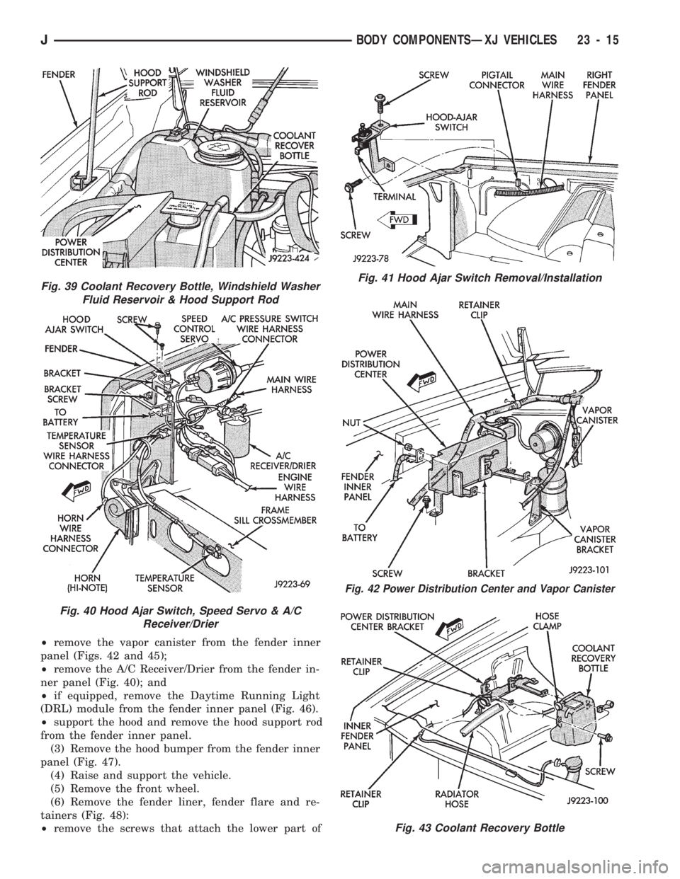
²remove the vapor canister from the fender inner
panel (Figs. 42 and 45);
²remove the A/C Receiver/Drier from the fender in-
ner panel (Fig. 40); and
²if equipped, remove the Daytime Running Light
(DRL) module from the fender inner panel (Fig. 46).
²support the hood and remove the hood support rod
from the fender inner panel.
(3) Remove the hood bumper from the fender inner
panel (Fig. 47).
(4) Raise and support the vehicle.
(5) Remove the front wheel.
(6) Remove the fender liner, fender flare and re-
tainers (Fig. 48):
²remove the screws that attach the lower part of
Fig. 41 Hood Ajar Switch Removal/Installation
Fig. 42 Power Distribution Center and Vapor Canister
Fig. 43 Coolant Recovery Bottle
Fig. 39 Coolant Recovery Bottle, Windshield Washer
Fluid Reservoir & Hood Support Rod
Fig. 40 Hood Ajar Switch, Speed Servo & A/C
Receiver/Drier
JBODY COMPONENTSÐXJ VEHICLES 23 - 15
Page 1471 of 1784
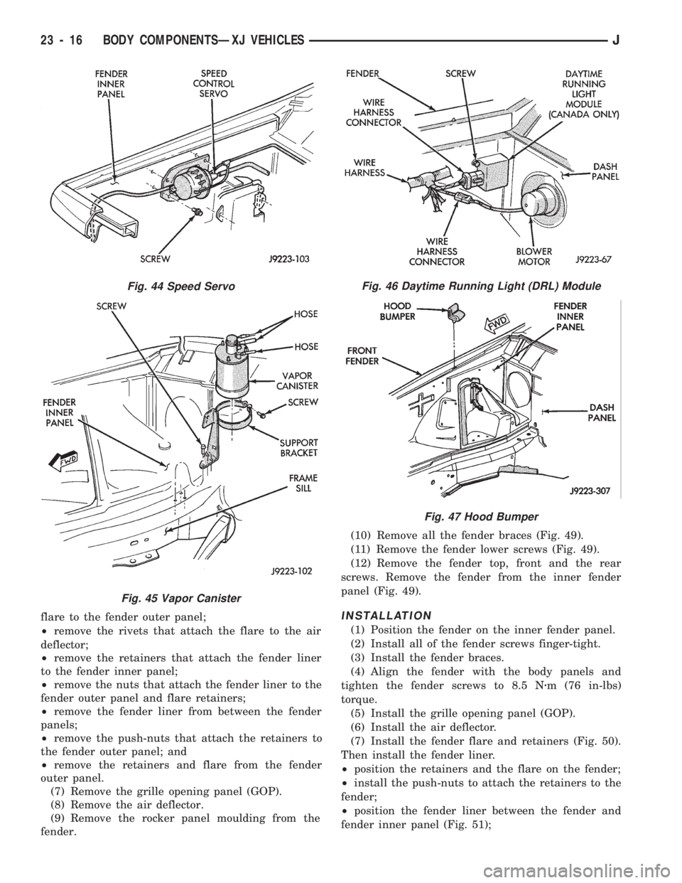
flare to the fender outer panel;
²remove the rivets that attach the flare to the air
deflector;
²remove the retainers that attach the fender liner
to the fender inner panel;
²remove the nuts that attach the fender liner to the
fender outer panel and flare retainers;
²remove the fender liner from between the fender
panels;
²remove the push-nuts that attach the retainers to
the fender outer panel; and
²remove the retainers and flare from the fender
outer panel.
(7) Remove the grille opening panel (GOP).
(8) Remove the air deflector.
(9) Remove the rocker panel moulding from the
fender.(10) Remove all the fender braces (Fig. 49).
(11) Remove the fender lower screws (Fig. 49).
(12) Remove the fender top, front and the rear
screws. Remove the fender from the inner fender
panel (Fig. 49).INSTALLATION
(1) Position the fender on the inner fender panel.
(2) Install all of the fender screws finger-tight.
(3) Install the fender braces.
(4) Align the fender with the body panels and
tighten the fender screws to 8.5 Nzm (76 in-lbs)
torque.
(5) Install the grille opening panel (GOP).
(6) Install the air deflector.
(7) Install the fender flare and retainers (Fig. 50).
Then install the fender liner.
²position the retainers and the flare on the fender;
²install the push-nuts to attach the retainers to the
fender;
²position the fender liner between the fender and
fender inner panel (Fig. 51);
Fig. 44 Speed Servo
Fig. 45 Vapor Canister
Fig. 46 Daytime Running Light (DRL) Module
Fig. 47 Hood Bumper
23 - 16 BODY COMPONENTSÐXJ VEHICLESJ
Page 1472 of 1784
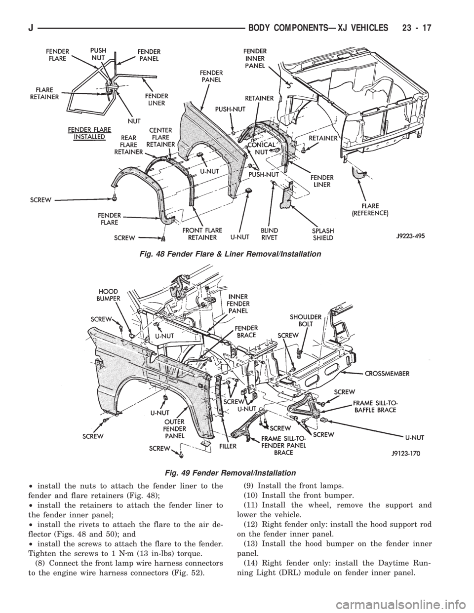
²install the nuts to attach the fender liner to the
fender and flare retainers (Fig. 48);
²install the retainers to attach the fender liner to
the fender inner panel;
²install the rivets to attach the flare to the air de-
flector (Figs. 48 and 50); and
²install the screws to attach the flare to the fender.
Tighten the screws to 1 Nzm (13 in-lbs) torque.
(8) Connect the front lamp wire harness connectors
to the engine wire harness connectors (Fig. 52).(9) Install the front lamps.
(10) Install the front bumper.
(11) Install the wheel, remove the support and
lower the vehicle.
(12) Right fender only: install the hood support rod
on the fender inner panel.
(13) Install the hood bumper on the fender inner
panel.
(14) Right fender only: install the Daytime Run-
ning Light (DRL) module on fender inner panel.
Fig. 48 Fender Flare & Liner Removal/Installation
Fig. 49 Fender Removal/Installation
JBODY COMPONENTSÐXJ VEHICLES 23 - 17
Page 1546 of 1784
INTERIOR COMPONENTS
INDEX
page page
Assist HandleÐXJ Vehicles................ 118
B/C-Pillar and Liftgate Pillar Trim CoversÐ
XJ Vehicles.......................... 116
Bucket Seat Cushion and Cover............. 98
Bucket Seat Platform and Tracks........... 105
Bucket Seatback Cover and Frame.......... 100
Bucket Seatback Reconditioning............ 102
Carpets and Floor Mats................... 129
Dash Panel Insulation Panel................ 95
Front Bucket Seats....................... 97
Front Carpet/MatÐXJ Vehicles............. 129
Front Inner Scuff Plate/Cowl Side Trim PanelÐ
XJ Vehicles.......................... 114
Front Shoulder Belt/BuckleÐXJ Vehicles...... 119
Full Floor ConsoleÐXJ Vehicles............ 125
Headliner.............................. 121
I/P Ash Receiver Tray Lamp................ 92
I/P Tweeter Speaker/Courtesy Lamp Support
Bracket.............................. 95
Instrument Cluster Bezel................... 91
Instrument Cluster/Switch/Lighter/Radio/Hevac . . . 91
Instrument Panel......................... 93
Interior Trim Panels and Scuff PlatesÐXJ Vehicles. 112
Jack StorageÐXJ Vehicles................ 127
Mini-Floor ConsoleÐXJ Vehicles............ 124
Outer Scuff PlatesÐXJ Vehicles............ 118
Power Bucket Seat Components............ 106
Quarter and Wheelhouse Trim PanelsÐ
XJ Vehicles.......................... 115
Quarter Trim Panel ExtensionÐXJ Vehicles . . . 115
Rear Carpet/MatÐXJ Vehicles.............. 130
Rear Seat Cushion CoverÐXJ Vehicles...... 107
Rear Seat Cushion ReconditioningÐXJ Vehicles . 108
Rear Seat CushionÐXJ Vehicles............ 107
Rear Seatback CoverÐXJ Vehicles.......... 111
Rear Seatback Latch Striker and BumperÐ
XJ Vehicles.......................... 111
Rear Seatback ReconditioningÐXJ Vehicles . . . 111
Rear SeatbackÐXJ Vehicles............... 109
Rear Shoulder/Lap Belt/BuckleÐXJ Vehicles . . . 120
Spare Tire/Wheel Holddown and Floor BracketsÐ
XJ Vehicles.......................... 128
Sunvisors............................. 124
Windshield Side MouldingÐXJ Vehicles...... 114
INSTRUMENT CLUSTER BEZEL
REMOVAL
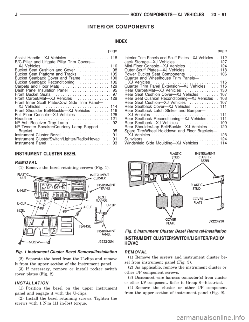
(1) Remove the bezel retaining screws (Fig. 1).
(2) Separate the bezel from the U-clips and remove
it from the upper section of the instrument panel.
(3) If necessary, remove or install rocker switch
cover plates (Fig. 2).
INSTALLATION
(1) Position the bezel on the upper instrument
panel and engage it with the U-clips.
(2) Install the bezel retaining screws. Tighten the
screws with 1 Nzm (11 in-lbs) torque.
INSTRUMENT CLUSTER/SWITCH/LIGHTER/RADIO/
HEVAC
REMOVAL
(1) Remove the screws and instrument cluster be-
zel from instrument panel (Fig. 3).
(2) As applicable, remove the instrument cluster or
other I/P component screws.
(3) Disconnect wire harness connector(s) from cluster
or other I/P component. Refer to Group 8ÐElectrical.
(4) Remove the cluster or other I/P component
from the upper section of instrument panel (Fig. 9).
Fig. 1 Instrument Cluster Bezel Removal/Installation
Fig. 2 Instrument Cluster Bezel Removal/Installation
JBODY COMPONENTSÐXJ VEHICLES 23 - 91
Page 1634 of 1784
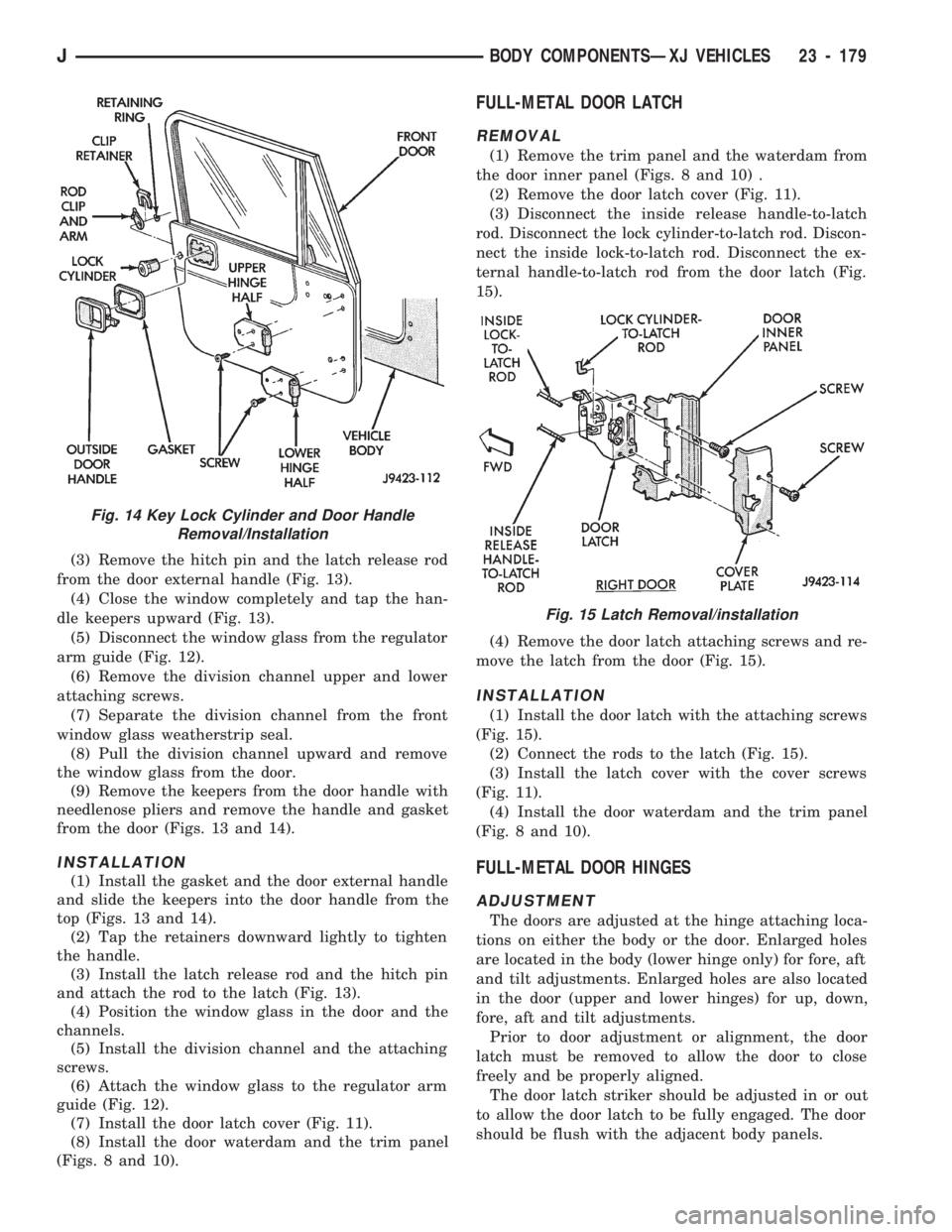
(3) Remove the hitch pin and the latch release rod
from the door external handle (Fig. 13).
(4) Close the window completely and tap the han-
dle keepers upward (Fig. 13).
(5) Disconnect the window glass from the regulator
arm guide (Fig. 12).
(6) Remove the division channel upper and lower
attaching screws.
(7) Separate the division channel from the front
window glass weatherstrip seal.
(8) Pull the division channel upward and remove
the window glass from the door.
(9) Remove the keepers from the door handle with
needlenose pliers and remove the handle and gasket
from the door (Figs. 13 and 14).
INSTALLATION
(1) Install the gasket and the door external handle
and slide the keepers into the door handle from the
top (Figs. 13 and 14).
(2) Tap the retainers downward lightly to tighten
the handle.
(3) Install the latch release rod and the hitch pin
and attach the rod to the latch (Fig. 13).
(4) Position the window glass in the door and the
channels.
(5) Install the division channel and the attaching
screws.
(6) Attach the window glass to the regulator arm
guide (Fig. 12).
(7) Install the door latch cover (Fig. 11).
(8) Install the door waterdam and the trim panel
(Figs. 8 and 10).
FULL-METAL DOOR LATCH
REMOVAL
(1) Remove the trim panel and the waterdam from
the door inner panel (Figs. 8 and 10) .
(2) Remove the door latch cover (Fig. 11).
(3) Disconnect the inside release handle-to-latch
rod. Disconnect the lock cylinder-to-latch rod. Discon-
nect the inside lock-to-latch rod. Disconnect the ex-
ternal handle-to-latch rod from the door latch (Fig.
15).
(4) Remove the door latch attaching screws and re-
move the latch from the door (Fig. 15).
INSTALLATION
(1) Install the door latch with the attaching screws
(Fig. 15).
(2) Connect the rods to the latch (Fig. 15).
(3) Install the latch cover with the cover screws
(Fig. 11).
(4) Install the door waterdam and the trim panel
(Fig. 8 and 10).
FULL-METAL DOOR HINGES
ADJUSTMENT
The doors are adjusted at the hinge attaching loca-
tions on either the body or the door. Enlarged holes
are located in the body (lower hinge only) for fore, aft
and tilt adjustments. Enlarged holes are also located
in the door (upper and lower hinges) for up, down,
fore, aft and tilt adjustments.
Prior to door adjustment or alignment, the door
latch must be removed to allow the door to close
freely and be properly aligned.
The door latch striker should be adjusted in or out
to allow the door latch to be fully engaged. The door
should be flush with the adjacent body panels.
Fig. 15 Latch Removal/installation
Fig. 14 Key Lock Cylinder and Door Handle
Removal/Installation
JBODY COMPONENTSÐXJ VEHICLES 23 - 179
Page 1658 of 1784
BUFFING AND POLISHING
Minor paint defects in a base/colorcoat can fre-
quently be removed by light sanding, buffing and
polishing. Wet sand the defect with 600 grit paper
soaked in mineral spirits.
Buff the surface area with a fine grade buffing
compound. Finish the repair with a quality polishing
compound to blend and restore the gloss.
BODY UNDERCOAT
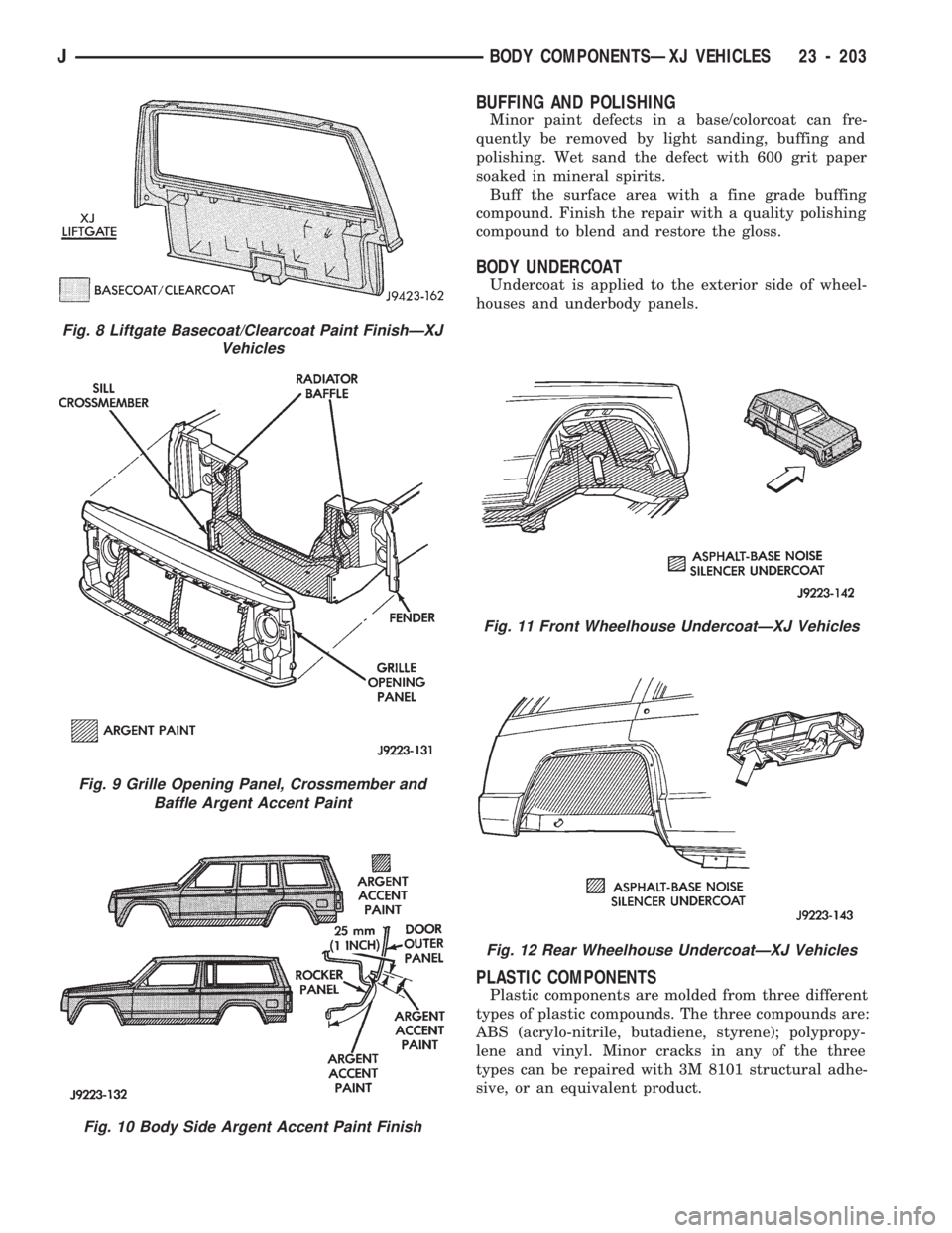
Undercoat is applied to the exterior side of wheel-
houses and underbody panels.
PLASTIC COMPONENTS
Plastic components are molded from three different
types of plastic compounds. The three compounds are:
ABS (acrylo-nitrile, butadiene, styrene); polypropy-
lene and vinyl. Minor cracks in any of the three
types can be repaired with 3M 8101 structural adhe-
sive, or an equivalent product.
Fig. 8 Liftgate Basecoat/Clearcoat Paint FinishÐXJ
Vehicles
Fig. 9 Grille Opening Panel, Crossmember and
Baffle Argent Accent Paint
Fig. 10 Body Side Argent Accent Paint Finish
Fig. 11 Front Wheelhouse UndercoatÐXJ Vehicles
Fig. 12 Rear Wheelhouse UndercoatÐXJ Vehicles
JBODY COMPONENTSÐXJ VEHICLES 23 - 203
Page 1666 of 1784
MANIFOLD
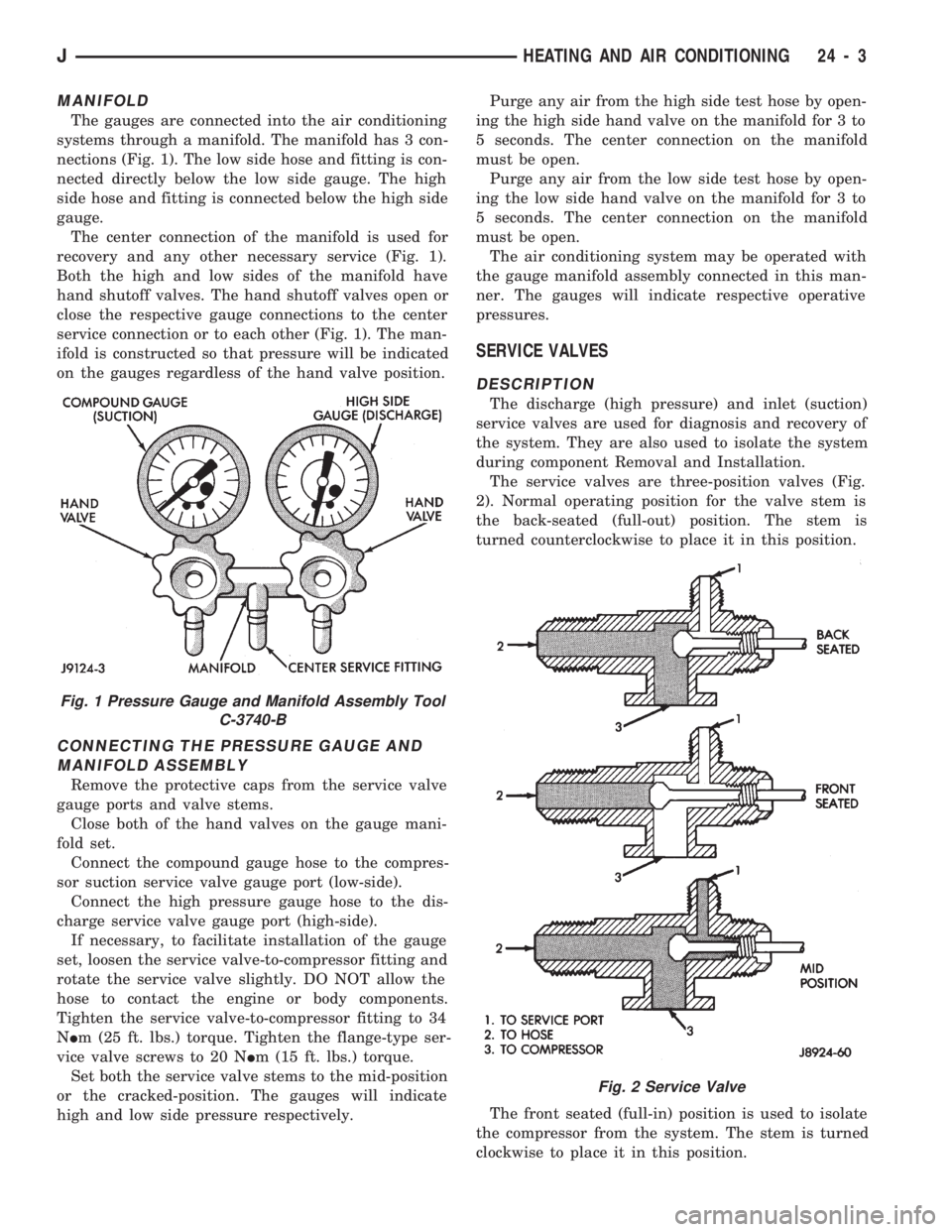
The gauges are connected into the air conditioning
systems through a manifold. The manifold has 3 con-
nections (Fig. 1). The low side hose and fitting is con-
nected directly below the low side gauge. The high
side hose and fitting is connected below the high side
gauge.
The center connection of the manifold is used for
recovery and any other necessary service (Fig. 1).
Both the high and low sides of the manifold have
hand shutoff valves. The hand shutoff valves open or
close the respective gauge connections to the center
service connection or to each other (Fig. 1). The man-
ifold is constructed so that pressure will be indicated
on the gauges regardless of the hand valve position.
CONNECTING THE PRESSURE GAUGE AND
MANIFOLD ASSEMBLY
Remove the protective caps from the service valve
gauge ports and valve stems.
Close both of the hand valves on the gauge mani-
fold set.
Connect the compound gauge hose to the compres-
sor suction service valve gauge port (low-side).
Connect the high pressure gauge hose to the dis-
charge service valve gauge port (high-side).
If necessary, to facilitate installation of the gauge
set, loosen the service valve-to-compressor fitting and
rotate the service valve slightly. DO NOT allow the
hose to contact the engine or body components.
Tighten the service valve-to-compressor fitting to 34
NIm (25 ft. lbs.) torque. Tighten the flange-type ser-
vice valve screws to 20 NIm (15 ft. lbs.) torque.
Set both the service valve stems to the mid-position
or the cracked-position. The gauges will indicate
high and low side pressure respectively.Purge any air from the high side test hose by open-
ing the high side hand valve on the manifold for 3 to
5 seconds. The center connection on the manifold
must be open.
Purge any air from the low side test hose by open-
ing the low side hand valve on the manifold for 3 to
5 seconds. The center connection on the manifold
must be open.
The air conditioning system may be operated with
the gauge manifold assembly connected in this man-
ner. The gauges will indicate respective operative
pressures.
SERVICE VALVES
DESCRIPTION
The discharge (high pressure) and inlet (suction)
service valves are used for diagnosis and recovery of
the system. They are also used to isolate the system
during component Removal and Installation.
The service valves are three-position valves (Fig.
2). Normal operating position for the valve stem is
the back-seated (full-out) position. The stem is
turned counterclockwise to place it in this position.
The front seated (full-in) position is used to isolate
the compressor from the system. The stem is turned
clockwise to place it in this position.
Fig. 1 Pressure Gauge and Manifold Assembly Tool
C-3740-B
Fig. 2 Service Valve
JHEATING AND AIR CONDITIONING 24 - 3
Page 1682 of 1784
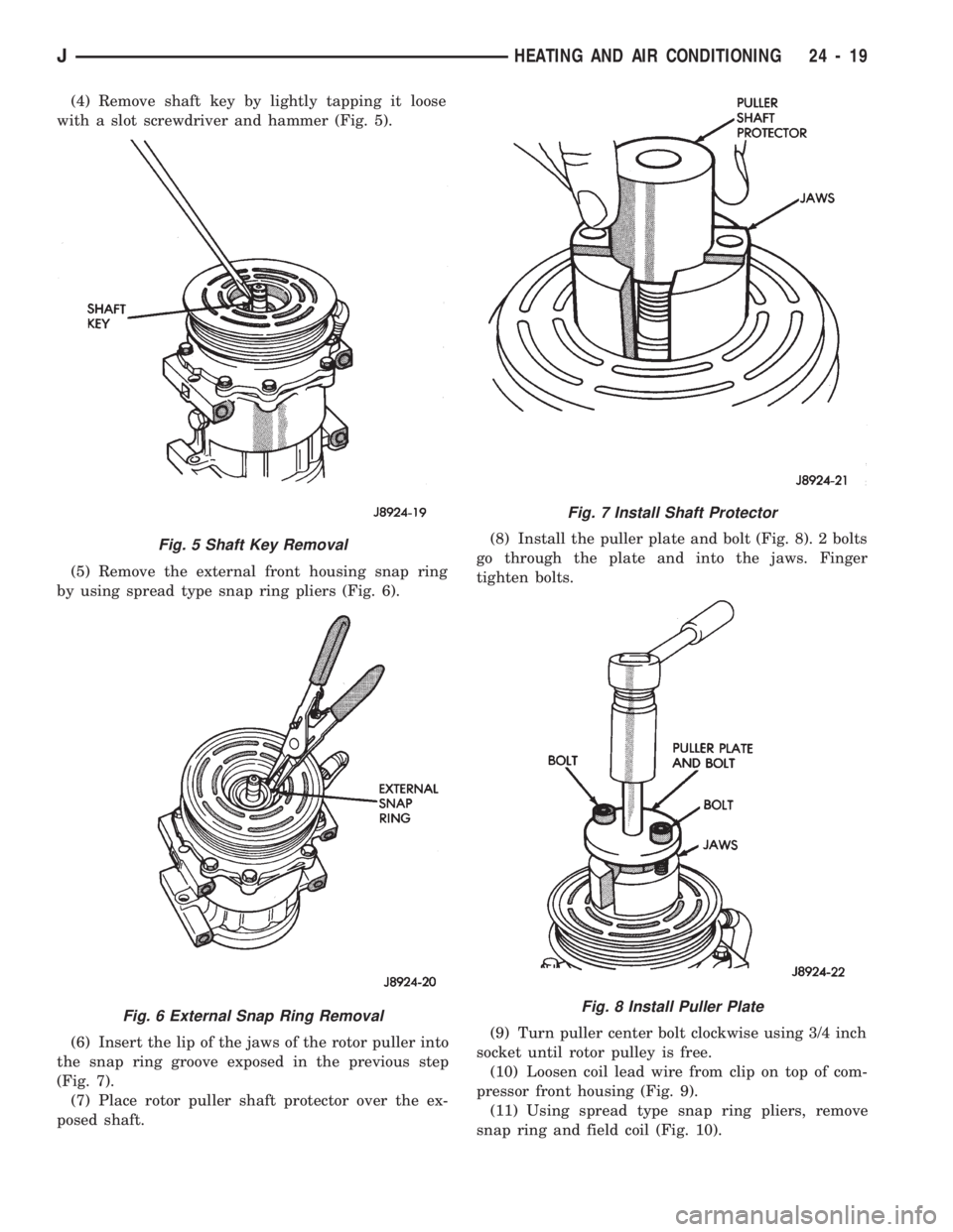
(4) Remove shaft key by lightly tapping it loose
with a slot screwdriver and hammer (Fig. 5).
(5) Remove the external front housing snap ring
by using spread type snap ring pliers (Fig. 6).
(6) Insert the lip of the jaws of the rotor puller into
the snap ring groove exposed in the previous step
(Fig. 7).
(7) Place rotor puller shaft protector over the ex-
posed shaft.(8) Install the puller plate and bolt (Fig. 8). 2 bolts
go through the plate and into the jaws. Finger
tighten bolts.
(9) Turn puller center bolt clockwise using 3/4 inch
socket until rotor pulley is free.
(10) Loosen coil lead wire from clip on top of com-
pressor front housing (Fig. 9).
(11) Using spread type snap ring pliers, remove
snap ring and field coil (Fig. 10).
Fig. 5 Shaft Key Removal
Fig. 6 External Snap Ring Removal
Fig. 7 Install Shaft Protector
Fig. 8 Install Puller Plate
JHEATING AND AIR CONDITIONING 24 - 19