1994 JEEP CHEROKEE front light
[x] Cancel search: front lightPage 209 of 1784
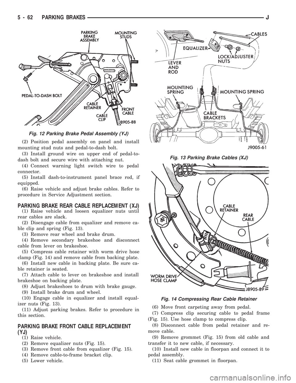
(2) Position pedal assembly on panel and install
mounting stud nuts and pedal-to-dash bolt.
(3) Install ground wire on upper end of pedal-to-
dash bolt and secure wire with attaching nut.
(4) Connect warning light switch wire to pedal
connector.
(5) Install dash-to-instrument panel brace rod, if
equipped.
(6) Raise vehicle and adjust brake cables. Refer to
procedure in Service Adjustment section.
PARKING BRAKE REAR CABLE REPLACEMENT (XJ)
(1) Raise vehicle and loosen equalizer nuts until
rear cables are slack.
(2) Disengage cable from equalizer and remove ca-
ble clip and spring (Fig. 13).
(3) Remove rear wheel and brake drum.
(4) Remove secondary brakeshoe and disconnect
cable from lever on brakeshoe.
(5) Compress cable retainer with worm drive hose
clamp (Fig. 14) and remove cable from backing plate.
(6) Install new cable in backing plate. Be sure ca-
ble retainer is seated.
(7) Attach cable to lever on brakeshoe and install
brakeshoe on backing plate.
(8) Adjust brakeshoes to drum with brake gauge.
(9) Install brake drum and wheel.
(10) Engage cable in equalizer and install equal-
izer nuts (Fig. 13).
(11) Adjust parking brakes. Refer to procedure in
this section.
PARKING BRAKE FRONT CABLE REPLACEMENT
(YJ)
(1) Raise vehicle.
(2) Remove equalizer nuts (Fig. 15).
(3) Remove front cable from equalizer (Fig. 15).
(4) Remove cable-to-frame bracket clip.
(5) Lower vehicle.(6) Move front carpeting away from pedal.
(7) Compress clip securing cable to pedal frame
(Fig. 15). Use hose clamp to compress clip.
(8) Disconnect cable from pedal retainer and re-
move cable.
(9) Remove grommet (Fig. 15) from old cable and
transfer it to new cable, if necessary.
(10) Install new cable in floorpan and connect it to
pedal assembly.
(11) Seat cable grommet in floorpan.
Fig. 12 Parking Brake Pedal Assembly (YJ)
Fig. 13 Parking Brake Cables (XJ)
Fig. 14 Compressing Rear Cable Retainer
5 - 62 PARKING BRAKESJ
Page 226 of 1784
RELEASE BEARING REPLACEMENT
(1) Remove transmission as described in Group 21.
(2) Disconnect release bearing from release lever
and remove bearing (Fig. 5).
(3) Inspect bearing slide surface of transmission
front bearing retainer. Replace retainer if slide sur-
face is scored, worn, or cracked.
(4) Inspect release fork and fork pivot. Be sure
pivot is secure and in good condition. Be sure fork is
not distorted or worn. Replace release fork retainer
spring if bent or damaged in any way.
(5) Lubricate crankshaft pilot bearing with Mopar
high temperature bearing grease. Apply grease to
end of long shank, small diameter flat blade screw-
driver. Then insert tool through clutch disc hub to
reach bearing.
(6) Lubricate input shaft splines, bearing retainer
slide surface, fork pivot and release fork pivot sur-face with Mopar high temperature grease.
(7) Install new release bearing. Be sure bearing is
properly secured to release fork.
(8) Install transmission as described in Group 21.
PILOT BEARING REPLACEMENT
(1) Remove transmission. Refer to Group 21 for
procedure.
(2) Remove clutch cover and disc.
(3) Remove pilot bearing. Use internal (blind hole)
puller such those as supplied in Snap On Tool Set
CG40CB to remove bearing.
(4) Lubricate new bearing with Mopar high tem-
perature bearing grease.
(5) Start new bearing into crankshaft by hand.
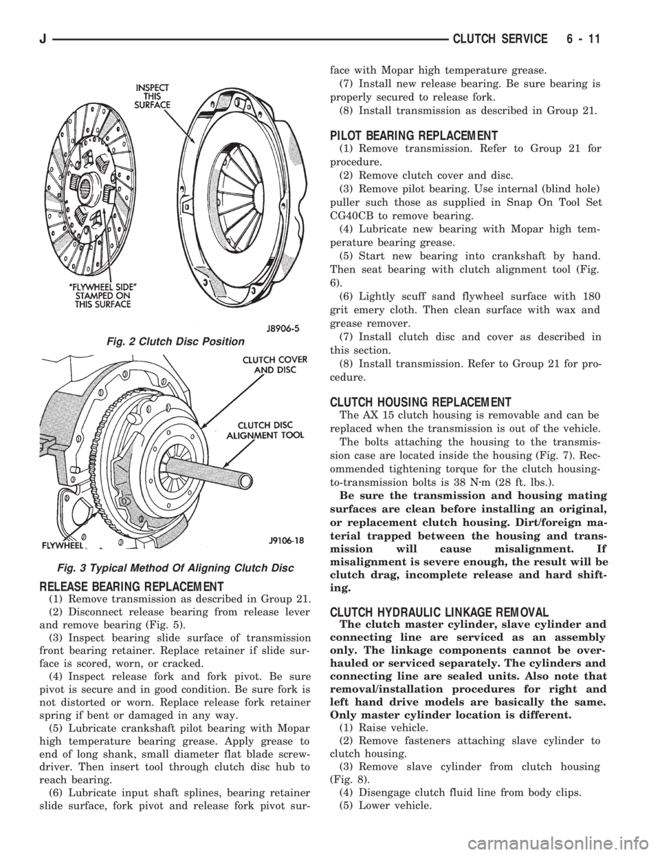
Then seat bearing with clutch alignment tool (Fig.
6).
(6) Lightly scuff sand flywheel surface with 180
grit emery cloth. Then clean surface with wax and
grease remover.
(7) Install clutch disc and cover as described in
this section.
(8) Install transmission. Refer to Group 21 for pro-
cedure.
CLUTCH HOUSING REPLACEMENT
The AX 15 clutch housing is removable and can be
replaced when the transmission is out of the vehicle.
The bolts attaching the housing to the transmis-
sion case are located inside the housing (Fig. 7). Rec-
ommended tightening torque for the clutch housing-
to-transmission bolts is 38 Nzm (28 ft. lbs.).
Be sure the transmission and housing mating
surfaces are clean before installing an original,
or replacement clutch housing. Dirt/foreign ma-
terial trapped between the housing and trans-
mission will cause misalignment. If
misalignment is severe enough, the result will be
clutch drag, incomplete release and hard shift-
ing.
CLUTCH HYDRAULIC LINKAGE REMOVAL
The clutch master cylinder, slave cylinder and
connecting line are serviced as an assembly
only. The linkage components cannot be over-
hauled or serviced separately. The cylinders and
connecting line are sealed units. Also note that
removal/installation procedures for right and
left hand drive models are basically the same.
Only master cylinder location is different.
(1) Raise vehicle.
(2) Remove fasteners attaching slave cylinder to
clutch housing.
(3) Remove slave cylinder from clutch housing
(Fig. 8).
(4) Disengage clutch fluid line from body clips.
(5) Lower vehicle.
Fig. 2 Clutch Disc Position
Fig. 3 Typical Method Of Aligning Clutch Disc
JCLUTCH SERVICE 6 - 11
Page 260 of 1784
speed of the fan to a predetermined maximum level
at higher engine speeds. A bimetallic spring coil is
located on the front face. This spring coil reacts to
the temperature of the radiator discharge air. It en-
gages the viscous fan drive for higher fan speed if
the air temperature from the radiator rises above a
certain point. Until additional engine cooling is nec-
essary, the fan will remain at a reduced rpm regard-
less of engine speed.
Only when sufficient heat is present, will the vis-
cous fan drive engage. This is when the air flowing
through the radiator core causes a reaction from the
bimetallic coil. It then increases fan speed to provide
the necessary additional engine cooling.
Once the engine has cooled, the radiator discharge
temperature will drop. The bimetallic coil again re-
acts and the fan speed is reduced to the previous dis-
engaged speed.
CAUTION: Engines equipped with serpentine drive
belts have reverse rotating fans and viscous fan
drives. They are marked with the word REVERSE to
designate their usage. Installation of the wrong fan
or viscous fan drive can result in engine overheat-
ing.
VISCOUS FAN DRIVE TEST
The cooling system must be in good condition. This
is checked prior to performing the following test. It
also will ensure against excessively high coolant
temperature.
CAUTION: Be sure that there is adequate fan blade
clearance before drilling.(1) Drill a 3.18-mm (1/8-in) diameter hole in the
top center of the fan shroud.
(2) Obtain a dial thermometer with an 8 inch stem
(or equivalent). It should have a range of -18É-to-
105ÉC (0É-to-220É F). Insert thermometer through the
hole in the shroud. Be sure that there is adequate
clearance from the fan blades.
(3) Connect a tachometer and an engine ignition
timing light (timing light is to be used as a strobe
light).
(4) Block the air flow through the radiator. Secure
a sheet of plastic in front of the radiator (or air con-
ditioner condenser). Use tape at the top to secure the
plastic and be sure that the air flow is blocked.
(5) Be sure that the air conditioner (if equipped) is
turned off.
WARNING: USE EXTREME CAUTION WHEN THE
ENGINE IS OPERATING. DO NOT STAND IN A DI-
RECT LINE WITH THE FAN. DO NOT PUT YOUR
HANDS NEAR THE PULLEYS, BELTS OR FAN. DO
NOT WEAR LOOSE CLOTHING.
(6) Start the engine and operate at 2400 rpm with
the timing light (strobe light) aimed at the fan
blades. Within ten minutes the air temperature (in-
dicated on the dial thermometer) should be 88É C
(190É F). Satisfactory operation of the fan drive re-
quires that it engage before or at 88É C (190É F). En-
gagement is distinguishable by a definite increase in
flow noise. The timing light also will indicate an in-
crease in the speed of the fan.
(7) When the air temperature reaches 88É C (190É
F), remove the plastic sheet. Satisfactory operation of
the viscous fan requires the air temperature to drop
20É F (11É C) or more. A definite decrease of audible-
fan-air-flow-noise should be noticed. Replace defec-
tive fan assemblies.
VISCOUS FAN DRIVE REPLACEMENT
REMOVAL
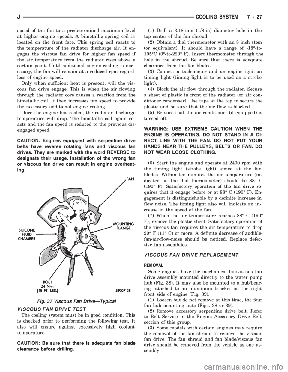
Some engines have the mechanical fan/viscous fan
drive assembly mounted directly to the water pump
hub (Fig. 38). It may also be mounted to a hub/bear-
ing attached to an aluminum bracket on the right
front side of engine (Fig. 39).
(1) Loosen but do not remove at this time, the four
fan hub mounting nuts (Figs. 38 or 39).
(2) Remove accessory serpentine drive belt. Refer
to Belt Service in the Engine Accessory Drive Belt
section of this group.
(3) Some models with certain engines may require
the removal of the fan shroud to remove the viscous
fan drive. The fan shroud and fan blade/viscous fan
drive should be removed from the vehicle as one as-
sembly.
Fig. 37 Viscous Fan DriveÐTypical
JCOOLING SYSTEM 7 - 27
Page 306 of 1784

OVERHEAD CONSOLE
CONTENTS
page page
COMPASS REPAIR PROCEDURES.......... 4
CONSOLE REPAIR PROCEDURES........... 6
DESCRIPTION........................... 1DIAGNOSTIC PROCEDURES............... 1
THERMOMETER AND SENSOR SYSTEM REPAIR
PROCEDURES......................... 6
DESCRIPTION
The overhead console includes:
²a compass/temperature display
²reading and courtesy lights for the front and rear
seats
²the receiver for the keyless entry system
²storage compartment for remote garage door
opener
²storage compartment for sunglasses.
COMPASS
The compass will display the direction the vehicle
is pointed, using the eight major compass headings
(Examples: North is ``N'', Northeast is ``NE''). It does
not display the headings in actual degrees. The dis-
play is turned on/off using the TEMP/COMP button
on the left of the display.
The compass is a self calibrating unit that should
not require recalibration. The only calibration that
may prove necessary is to drive the vehicle in 3 com-
plete circles, on level ground, in not less than 48 sec-
onds. This will ``reorient'' the unit to its vehicle. The
unit also will compensate for magnetism the vehicle
may acquire during its life. Care should be used to
avoid putting anything magnetic on the roof of the
vehicle.
The unit can compensate for some magnetic fields
in the body. The use of magnetic attachments like
antenna mounts or repair order ``hats'' placed di-
rectly on the roof can exceed the compensation abil-
ity of the unit. Magnetic bit drivers used on the
fasteners to hold the assembly to the roof header can
also affect operation. If the vehicle roof should be-
come magnetized, then the degaussing and calibra-
tion procedures may be required to restore proper
operation.
If the compass functions but accuracy is suspect, it
may be necessary to perform a variation adjustment.
This procedure allows the unit to accommodate vari-
ations in the earth's magnetic field strength based on
geographic location.
If the compass has blanked out and only CAL
appears, degaussing may be necessary to re-
move residual magnetic fields.
THERMOMETER
The ambient temperature display can be changed
from Fahrenheit to Celsius using the U.S./METRIC
button on the right of the display. The temperature
reported is not an instant reading of conditions but
an average temperature. It may take the unit several
minutes to react to a major change such as driving
out of a heated garage into winter temperatures.
When the ignition switch is turned OFF, the last
displayed temperature reading stays in memory.
When the ignition switch is turned ON again the
thermometer will display the memory temperature
for one minute; then update the display to the actual
temperature within five minutes.
READING AND COURTESY LAMPS
All reading and courtesy lamps in the overhead
console are activated by the door courtesy circuit.
When all four doors and the liftgate are closed the
lamps can be activated by depressing the correspond-
ing lens. When any door or the liftgate is open, the
switches are disabled. They will not turn the lamps
off.
MAP AND COURTESY LAMPS
These lamps offer several unique features. Both the
map and courtesy lamps can be turned on with the
integral ``Soft Touch'' switch. Pushing this switch en-
ergizes an electrical circuit, which in turn directs
power to the light. The map lamps are unaffected by
the door switches, while the courtesy lamps are
turned on with the opening of any door. When any
door is open, the ``Soft Touch'' switches are disabled,
you cannot turn the lights off with these switches.
DIAGNOSTIC PROCEDURES
Follow the appropriate diagnostic flow chart:
²Chart 1 describes the procedures for compass and
display problems.
²Chart 2 describes the procedures for illumination
lamp problems.
²Chart 3 describes the procedures for outside tem-
perature measuring problems.
JOVERHEAD CONSOLE 8C - 1
Page 310 of 1784
circles, in not less than 48 seconds. The CAL light
will go off and the compass is now calibrated.
(5) Reset variation number. This step must be
done every time step 2 is performed.
If CAL light does not go off, either there is ex-
cessive magnetism near the compass or the unit
is defective. Repeat the degaussing and calibra-
tion procedures at least one more time.
If the wrong direction is still indicated, the
area selected may be too close to a magnetic
source. Repeat the calibration procedure in an-
other location.
DEGAUSSING PROCEDURE
The tool used to degauss or demagnetize the forward
console attaching screw and roof panel is the Miller
Tool 6029. Equivalent units must be rated as continu-
ous duty for 110/115 volts, 60Hz with a field strength of
over 350 gauss at 1/4 inch beyond the tip of the probe.
In this degaussing procedure the degaussing tool is
used to demagnetize both the roof panel and console
forward mounting screw.
(1) Be sure the ignition switch is in the OFF posi-
tion before you begin the degaussing procedures.
CAUTION: Keep the degaussing tool at least 2 inches
away from the compass area when plugging it in.
(2) Plug the degaussing tool into a standard
110/115 volt AC outlet.
CONSOLE FORWARD MOUNTING SCREW
(3) Slowly approach the head of the forward
mounting screw with the plastic coated tip of the de-
gaussing tool. Contact the head of the screw for
about two seconds.
(4) With the degaussing tool still energized, slowly
back it away from the screw until the tool is at least
2 inches from the screw head then unplug the tool.
ROOF PANEL
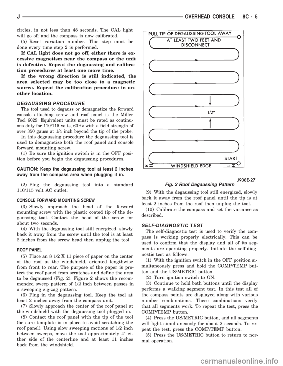
(5) Place an 8 1/2 X 11 piece of paper on the center
of the roof at the windshield, oriented lengthwise
from front to rear. The purpose of the paper is pro-
tect the roof panel from scratches and define the area
to be degaussed (Fig. 2). Figure 2 shows the recom-
mended sweep pattern of 1/2 inch between passes in
a sweeping zig-zag pattern.
(6) Plug in the degaussing tool. Keep the tool at
least 2 inches away from the compass unit.
(7) Slowly approach the center of the roof panel at
the windshield with the degaussing tool plugged in.
(8) Contact the roof panel with the tip of the tool
(be sure template is in place to avoid scratching the
roof panel). Using slow sweeping motions of 1/2 inch
between sweeps, move the tool approximately 49ei-
ther side of the centerline and at least 11 inches
back from the windshield.(9) With the degaussing tool still energized, slowly
back it away from the roof panel until the tip is at
least 2 inches from the roof then unplug the tool.
(10) Calibrate the compass and set the variance as
described.
SELF-DIAGNOSTIC TEST
The self-diagnostic test is used to verify the com-
pass is working properly electrically. This can be
used to confirm that the display and all of its seg-
ments are operating properly. Initiate the self-diag-
nostic test as follows:
(1) With the ignition switch in the OFF position si-
multaneously press and hold the COMP/TEMP but-
ton and the US/METRIC button.
(2) Turn ignition switch to ON.
(3) Continue to hold both buttons until the display
performs a walking segment test. In this test all of
the compass points are displayed along with various
number combinations. These combinations verify
that all segments work. To repeat the test, press the
COMP/TEMP button.
(4) Press the US/METRIC button, and all segments
will light simultaneously for about 2 seconds. To re-
peat the test, press the COMP/TEMP button.
(5) Press the US/METRIC button to return to nor-
mal operation.
Fig. 2 Roof Degaussing Pattern
JOVERHEAD CONSOLE 8C - 5
Page 311 of 1784
(6) Should any segment in any of the digit positions
fail to light, the unit is defective and should be re-
placed.
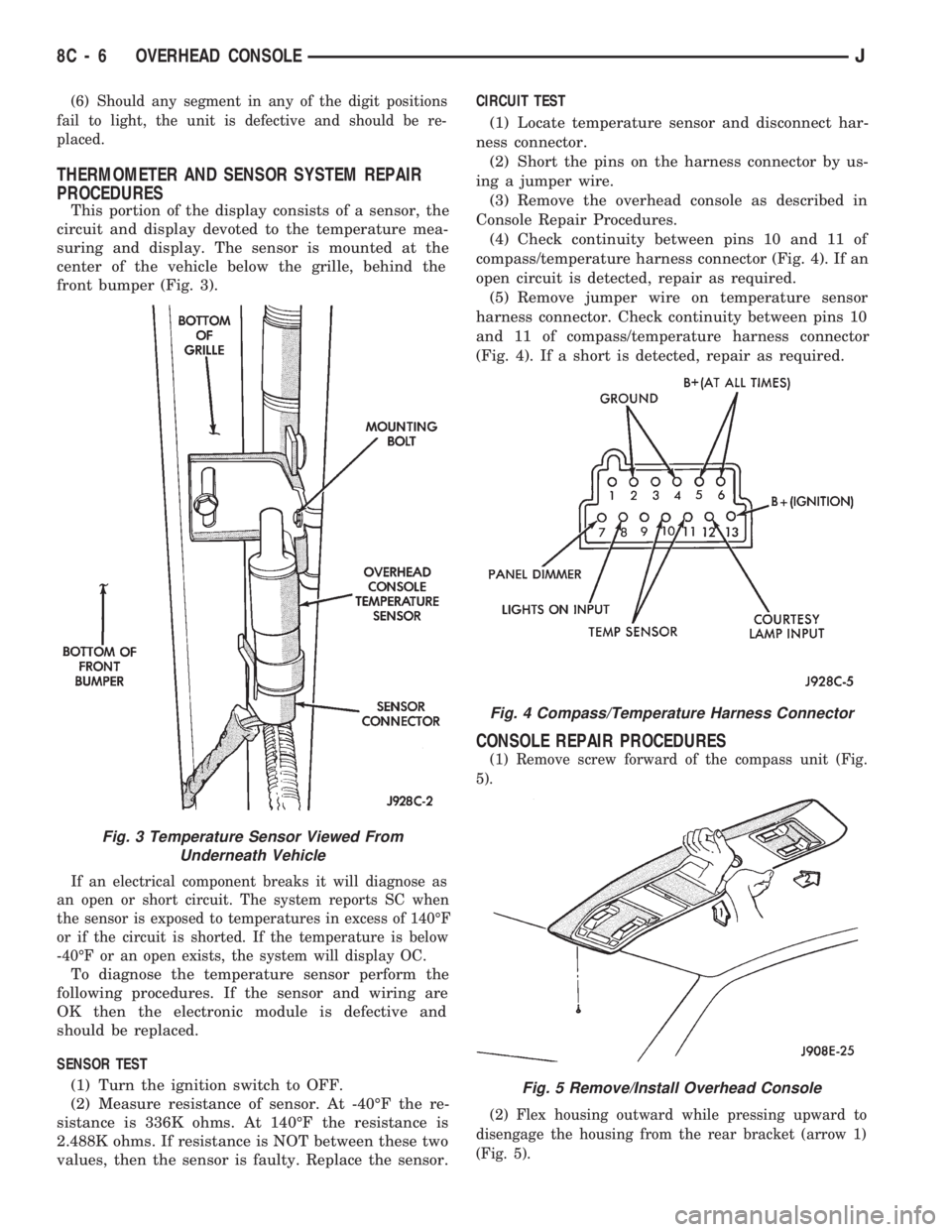
THERMOMETER AND SENSOR SYSTEM REPAIR
PROCEDURES
This portion of the display consists of a sensor, the
circuit and display devoted to the temperature mea-
suring and display. The sensor is mounted at the
center of the vehicle below the grille, behind the
front bumper (Fig. 3).
If an electrical component breaks it will diagnose as
an open or short circuit. The system reports SC when
the sensor is exposed to temperatures in excess of 140ÉF
or if the circuit is shorted. If the temperature is below
-40ÉF or an open exists, the system will display OC.
To diagnose the temperature sensor perform the
following procedures. If the sensor and wiring are
OK then the electronic module is defective and
should be replaced.
SENSOR TEST
(1) Turn the ignition switch to OFF.
(2) Measure resistance of sensor. At -40ÉF the re-
sistance is 336K ohms. At 140ÉF the resistance is
2.488K ohms. If resistance is NOT between these two
values, then the sensor is faulty. Replace the sensor.CIRCUIT TEST
(1) Locate temperature sensor and disconnect har-
ness connector.
(2) Short the pins on the harness connector by us-
ing a jumper wire.
(3) Remove the overhead console as described in
Console Repair Procedures.
(4) Check continuity between pins 10 and 11 of
compass/temperature harness connector (Fig. 4). If an
open circuit is detected, repair as required.
(5) Remove jumper wire on temperature sensor
harness connector. Check continuity between pins 10
and 11 of compass/temperature harness connector
(Fig. 4). If a short is detected, repair as required.
CONSOLE REPAIR PROCEDURES
(1) Remove screw forward of the compass unit (Fig.
5).
(2) Flex housing outward while pressing upward to
disengage the housing from the rear bracket (arrow 1)
(Fig. 5).
Fig. 4 Compass/Temperature Harness Connector
Fig. 5 Remove/Install Overhead Console
Fig. 3 Temperature Sensor Viewed From
Underneath Vehicle
8C - 6 OVERHEAD CONSOLEJ
Page 338 of 1784
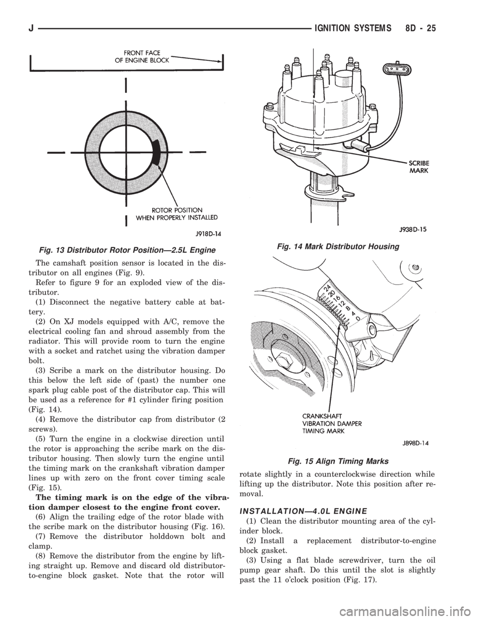
The camshaft position sensor is located in the dis-
tributor on all engines (Fig. 9).
Refer to figure 9 for an exploded view of the dis-
tributor.
(1) Disconnect the negative battery cable at bat-
tery.
(2) On XJ models equipped with A/C, remove the
electrical cooling fan and shroud assembly from the
radiator. This will provide room to turn the engine
with a socket and ratchet using the vibration damper
bolt.
(3) Scribe a mark on the distributor housing. Do
this below the left side of (past) the number one
spark plug cable post of the distributor cap. This will
be used as a reference for #1 cylinder firing position
(Fig. 14).
(4) Remove the distributor cap from distributor (2
screws).
(5) Turn the engine in a clockwise direction until
the rotor is approaching the scribe mark on the dis-
tributor housing. Then slowly turn the engine until
the timing mark on the crankshaft vibration damper
lines up with zero on the front cover timing scale
(Fig. 15).
The timing mark is on the edge of the vibra-
tion damper closest to the engine front cover.
(6) Align the trailing edge of the rotor blade with
the scribe mark on the distributor housing (Fig. 16).
(7) Remove the distributor holddown bolt and
clamp.
(8) Remove the distributor from the engine by lift-
ing straight up. Remove and discard old distributor-
to-engine block gasket. Note that the rotor willrotate slightly in a counterclockwise direction while
lifting up the distributor. Note this position after re-
moval.
INSTALLATIONÐ4.0L ENGINE
(1) Clean the distributor mounting area of the cyl-
inder block.
(2) Install a replacement distributor-to-engine
block gasket.
(3) Using a flat blade screwdriver, turn the oil
pump gear shaft. Do this until the slot is slightly
past the 11 o'clock position (Fig. 17).
Fig. 13 Distributor Rotor PositionÐ2.5L EngineFig. 14 Mark Distributor Housing
Fig. 15 Align Timing Marks
JIGNITION SYSTEMS 8D - 25
Page 352 of 1784
INSTRUMENT CLUSTER SERVICE PROCEDURES
INDEX
page page
Gauge ReplacementÐInstrument Cluster Removed.. 5
Gear Selector Indicator ReplacementÐInstrument
Cluster Removed........................ 6
Instrument Cluster Replacement.............. 5
Instrument Panel Replacement (Fig. 9)......... 8
Printed Circuit ReplacementÐInstrumentCluster Removed........................ 6
Speedometer ReplacementÐInstrument
Cluster Removed........................ 5
Tachometer ReplacementÐInstrument
Cluster Removed........................ 5
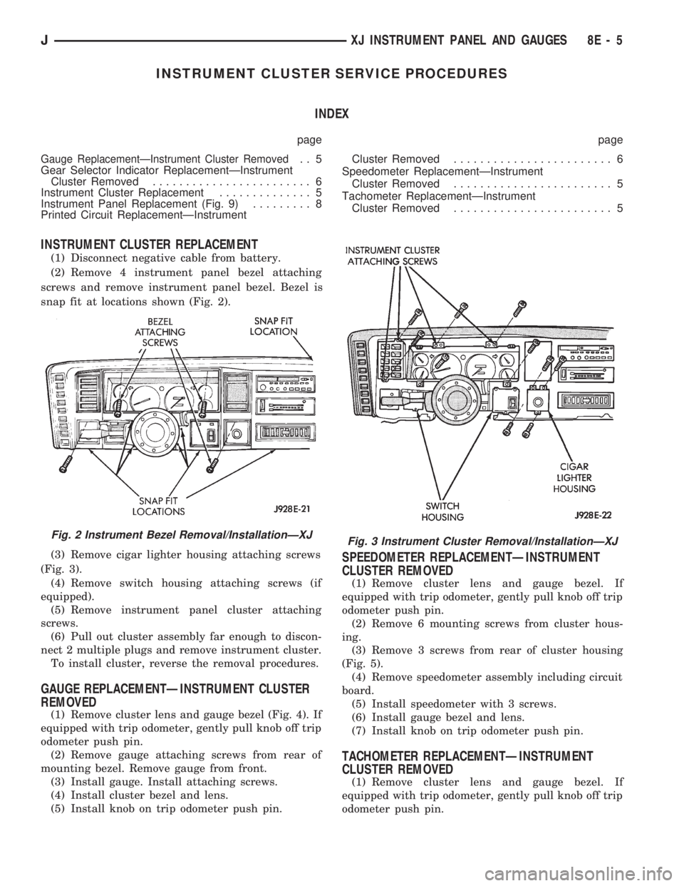
INSTRUMENT CLUSTER REPLACEMENT
(1) Disconnect negative cable from battery.
(2) Remove 4 instrument panel bezel attaching
screws and remove instrument panel bezel. Bezel is
snap fit at locations shown (Fig. 2).
(3) Remove cigar lighter housing attaching screws
(Fig. 3).
(4) Remove switch housing attaching screws (if
equipped).
(5) Remove instrument panel cluster attaching
screws.
(6) Pull out cluster assembly far enough to discon-
nect 2 multiple plugs and remove instrument cluster.
To install cluster, reverse the removal procedures.
GAUGE REPLACEMENTÐINSTRUMENT CLUSTER
REMOVED
(1) Remove cluster lens and gauge bezel (Fig. 4). If
equipped with trip odometer, gently pull knob off trip
odometer push pin.
(2) Remove gauge attaching screws from rear of
mounting bezel. Remove gauge from front.
(3) Install gauge. Install attaching screws.
(4) Install cluster bezel and lens.
(5) Install knob on trip odometer push pin.
SPEEDOMETER REPLACEMENTÐINSTRUMENT
CLUSTER REMOVED
(1) Remove cluster lens and gauge bezel. If
equipped with trip odometer, gently pull knob off trip
odometer push pin.
(2) Remove 6 mounting screws from cluster hous-
ing.
(3) Remove 3 screws from rear of cluster housing
(Fig. 5).
(4) Remove speedometer assembly including circuit
board.
(5) Install speedometer with 3 screws.
(6) Install gauge bezel and lens.
(7) Install knob on trip odometer push pin.
TACHOMETER REPLACEMENTÐINSTRUMENT
CLUSTER REMOVED
(1) Remove cluster lens and gauge bezel. If
equipped with trip odometer, gently pull knob off trip
odometer push pin.
Fig. 2 Instrument Bezel Removal/InstallationÐXJFig. 3 Instrument Cluster Removal/InstallationÐXJ
JXJ INSTRUMENT PANEL AND GAUGES 8E - 5