1994 JEEP CHEROKEE display
[x] Cancel search: displayPage 363 of 1784

DIAGNOSINGÐALL LAMPS OUT
(1) Inspect fuse #9. Replace as required.
(2) Measure voltage at instrument cluster connec-
tor terminal 20. Meter should read zero ohms. If not,
repair open to ground.
UPSHIFT INDICATOR LAMP
Vehicles equipped with manual transmissions have
an optional upshift indicator lamp. The lamp is con-
trolled by the PCM. The lamp lights to indicate when
the driver should shift to the next highest gear for best
fuel economy. The PCM will turn the lamp off after 3 to
5 seconds if the upshift is not performed. The lamp will
remain off until the vehicle stops accelerating and is
brought back to the range of lamp operation or shifted
into another gear.
The indicator lamp is normally illuminated when
the ignition switch is turned ON and it is turned off
when the engine is started. The lamp will be lighted
during engine operation according to engine speed
and load.
(1) Turn ignition switch to ON.
(2) Ground pin 2 of cluster connector. Lamp should
light. If not, replace bulb. If OK, continue with step 3.
(3) Turn ignition switch to OFF. Check for conti-
nuity between cluster connector pin 2 and pin 54 of
the PCM. If not, repair open. If OK, refer to DRB
scan tool actuator test of upshift indicator.
BRAKE INDICATOR LAMP
The brake indicator is a dual function lamp. It will in-
dicate an unequal pressure condition in the split brake
hydraulic system and it also will indicate when the park-
ing brake is engaged. Separate switches are used for each
indicator lamp function. A switch mounted on the brake
pedal assembly will close a ground circuit whenever the
parking brakes are applied. A second switch is installed
in the brake hydraulic lines near the master cylinder. If
the switch is balanced by equal pressure on both ends of
the switch valve, the valve remains centered and the
lamp remains off. If the valve is shifted by unequal pres-
sure between the front or rear brake hydraulic systems,
the lamp circuit is connected to ground. To make sure
the brake lamp is functional before the vehicle is driven,
it is illuminated through a ground circuit when the igni-
tion switch is turned to the START position.
(1) Turn ignition switch to ON.
(2) Ground pin 1 of the cluster connector. Lamp
should light. If not, replace bulb. If OK, continue
with step 3.
(3) Turn ignition switch to OFF. Check for continuity to
park brake switch and brake warning switch.
MALFUNCTION INDICATOR LAMP (CHECK ENGINE)
The Malfunction Indicator Lamp (Check Engine) il-
luminates each time the ignition switch is turned
ON and stays on for 3 seconds as a bulb test.If the PCM receives an incorrect signal or no signal
from certain sensors or emission related systems the
lamp is turned on (pin 32 of PCM). This is a warning
that the PCM has recorded a system or sensor mal-
function. In some cases when a diagnostic fault is de-
clared the PCM will go into a limp-in mode in an
attempt to keep the system operating. It signals an
immediate need for service.
The lamp also can be used to display diagnostic
trouble codes (DTC). Cycle the ignition switch ON,
OFF, ON, OFF, ON within 5 seconds. This will allow
any DTC's stored in the PCM memory to be dis-
played in a series of flashes representing digits.
(1) Turn ignition switch to ON.
(2) Ground pin 4 of cluster connector. Lamp should
light. If not, replace bulb. If OK, continue with step 3.
(3) Turn ignition switch to OFF. Check for conti-
nuity between cluster connector pin 4 and PCM cav-
ity 32. If OK, replace PCM. If not, repair open.
SEAT BELT REMINDER LAMP
Apply 12 volts to terminal 16 of cluster connector.
Lamp should light. If not, replace bulb. If OK, check
wiring for an open to buzzer module. Refer to Group
8U - Chime/Buzzer Warning Systems.
INSTRUMENT PANEL ILLUMINATION LAMPS
The instrument panel illumination lamps share
two common connections. There is a splice after fuse
#10 that connects the lamps to battery feed. There is
also a splice that connects all lamps to ground. Be-
cause they share these common connection points in
a parallel circuit, the illumination lamps will all
come on at the same time. It also means one or more
lamps can be out without affecting the operation of
the other lamps.
On the battery side of the circuit, the headlamp
switch illumination rheostat/switch and panel lamps
fuse receive battery feed in series from the park/tail
fuse. In the park lamp position, the headlamp switch
completes the circuit from the park/tail fuse to the il-
lumination rheostat/switch and panel lamps fuse.
The illumination rheostat contains a variable resis-
tor that allows the driver to vary illumination inten-
sity from off to full brightness.
DIAGNOSIS
(1) Turn parking lamps ON.
(2) Check fuse #10. Replace as required.
(3) Measure voltage at battery side of fuse #10
with rheostat turned counterclockwise to clockwise
(LO to HI). Meter should read zero volts to battery
voltage. If not, replace headlamp switch.
(4) Measure resistance at ground side of fuse #10
with parking lamps OFF. Meter should read almost
zero ohms (except bulb filament). If not, repair open
to ground. If zero ohms, 12 volt supply wire from fuse
is shorted to ground, repair short.
8E - 16 YJ INSTRUMENT PANEL AND GAUGESJ
Page 376 of 1784
AUDIO SYSTEMS
CONTENTS
page page
GENERAL INFORMATION.................. 1
RADIO ANTENNA........................ 8XJ SERVICE PROCEDURES................ 4
YJ SERVICE PROCEDURES................ 6
GENERAL INFORMATION
DESCRIPTION
Each radio receives ignition feed from an ignition
switch controlled fuse. There is an additional in-line
fuse in the back of the radio chassis. The in-line fuse
will blow in the event an internal short occurs.
The electronically tuned radio (ETR)/cassette
models protect the vehicle from a radio failure
with an in-line fuse located in the rear of the ra-
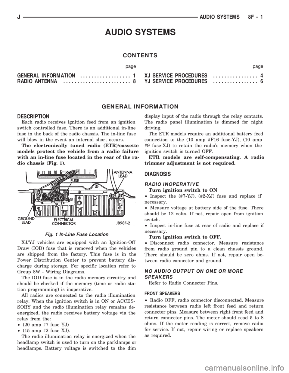
dio chassis (Fig. 1).
XJ/YJ vehicles are equipped with an Ignition-Off
Draw (IOD) fuse that is removed when the vehicles
are shipped from the factory. This fuse is in the
Power Distribution Center to prevent battery dis-
charge during storage. For specific location refer to
Group 8W - Wiring Diagrams.
The IOD fuse is in the radio memory circuitry and
should be checked if the memory (time or radio sta-
tion programming) is inoperative.
All radios are connected to the radio illumination
relay. When the ignition switch is in ON or ACCES-
SORY and the radio illumination relay remains de-
energized, the radio receives battery voltage via the
relay from the:
²(20 amp #7 fuse YJ)
²(15 amp #2 fuse XJ).
The radio illumination relay is energized when the
headlamp switch is used to turn on the parklamps or
headlamps. Battery voltage is switched to the dimdisplay input of the radio through the relay contacts.
The radio panel illumination is dimmed for night
driving.
The ETR models require an additional battery feed
connection to the (10 amp #F16 fuse-YJ), (10 amp
#9 fuse-XJ) to retain the radio's memory when the
ignition switch is turned OFF.
ETR models are self-compensating. A radio
trimmer adjustment is not required.
DIAGNOSIS
RADIO INOPERATIVE
Turn ignition switch to ON
²Inspect the (#7-YJ), (#2-XJ) fuse and replace if
necessary.
²Measure voltage at battery side of the fuse. There
should be 12 volts. If not, repair open from ignition
switch.
²Inspect in-line fuse at rear of radio and replace if
necessary.
Turn ignition switch to OFF.
²Disconnect radio connector. Measure resistance
from radio ground pin to a clean chassis ground.
There should be zero ohms. If not, repair open be-
tween radio connector and ground.
NO AUDIO OUTPUT ON ONE OR MORE
SPEAKERS
Refer to Radio Connector Pins.
FRONT SPEAKERS
²Radio OFF, radio connector disconnected. Measure
resistance between radio left front feed and return
connector pins. Measure between right front feed and
return connector pins. The meter should read 5 to 8
ohms. If the meter reading is correct, remove radio
for service. If not, repair wiring or replace speakers
as required.
Fig. 1 In-Line Fuse Location
JAUDIO SYSTEMS 8F - 1
Page 377 of 1784
REAR SPEAKERS
²Radio OFF, radio connector disconnected. Measure
resistance between radio left rear feed and return
connector pins. Measure between right rear feed and
return connector pins. The meter should read 5 to 8
ohms. If meter reading is correct remove radio for
service. If not, repair wiring or replace speakers as
required.
DISTORTED AUDIO OUTPUT ON ONE OR
MORE SPEAKERS
²With the radio ON, substitute known good speaker
or speakers. If the sound is still distorted, remove ra-
dio for service.
WEAK OR NO RECEPTION; NO AUDIO
OUTPUT; BACKGROUND NOISE PRESENT
Ignition switch in ON, radio ON.
²Inspect antenna cable and connector at radio and
tighten or repair as necessary.
²Unplug coax cable and connectors from radio. Mea-
sure resistance from center conductor to coaxial
shield. The meter should read infinite resistance
(open). If it does not, replace antenna assembly.
²Measure resistance of antenna mast to tip of cen-
ter conductor at radio end of cable. The meter should
read 0 to 0.5 ohms. If it does not, replace lead-in ca-
ble or antenna assembly.
²Measure resistance from coaxial shield to chassis
ground (vehicle body). The meter should read zero
ohms. If it does not, ground antenna base to vehicle
body, or replace antenna assembly as required
For all problems with no or low audio output
not resolved by these tests, remove radio for ser-
vice.
MEMORY DOES NOT OPERATE
²Inspect (F16 in Power Distribution Center-YJ),
(#9 in Fuse Panel-XJ) fuse and replace if necessary.
²Measure voltage at battery side of previously ref-
erenced fuse. There should be 12 volts at battery side
of fuse. If not, check the Maxi fuse.
Refer to Group 8W - Wiring Diagrams.
²Measure voltage at radio connector pin 4. There
should be 12 volts. If meter reading is correct, re-
move radio for service. If not, repair open from fuse.
RADIO DISPLAY ILLUMINATION (PARKLAMPS
AND HEADLAMPS OPERATING NORMALLY)
Headlamp switch OFF, radio ON.
²Measure voltage at radio connector pin 10. There
should be 12 volts. If not, go to next step. If OK, re-
move radio for repair by authorized outlet.
²Measure voltage at illumination relay pin 3. There
should be 12 volts. If 12 volts present, replace illumi-
nation relay. If not, repair open in circuit.RADIO DISPLAY ILLUMINATION DIMMING CIRCUIT
Turn headlamp switch to PARKLAMPS for
voltage tests; turn headlamp switch to OFF for
resistance tests.
²Separate relay connector from radio illumination
relay. Measure resistance from relay connector pin 2
to a clean chassis ground. The meter should read
zero ohms. If not, repair open between relay connec-
tor and ground.
²Measure voltage at radio illumination relay pin 5.
There should be battery voltage. If not repair open
from headlamp switch.
²Measure voltage at radio illumination relay pin 4.
Voltage should vary with dimmer switch. If OK, go
to next step. If not, repair open circuit between pin 4
and interior lamp rheostat.
²Measure voltage at radio illumination relay pin
10. Voltage should vary with dimmer switch. If OK,
remove radio for repair by authorized outlet. If not,
replace radio illumination relay.NOISE INTERFERENCE CHANGES WITH
ENGINE SPEED
²Inspect connections at: generator, ignition module,
antenna coaxial ground, radio ground, body to engine
block ground (braided ground strap). Repair as re-
quired.
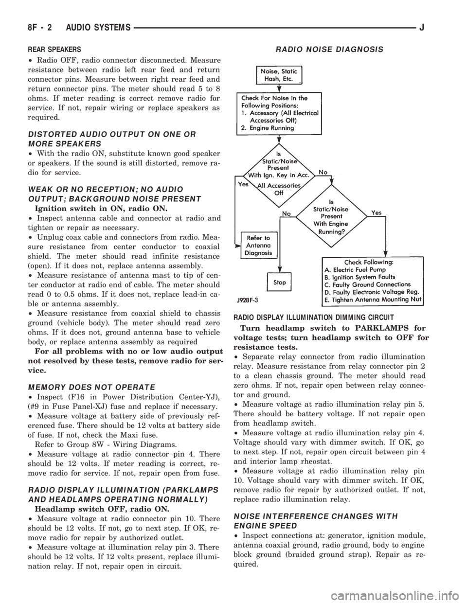
RADIO NOISE DIAGNOSIS
8F - 2 AUDIO SYSTEMSJ
Page 394 of 1784
TEST PROCEDURES
INDEX
page page
Checking for Diagnostic Trouble Code......... 5
Electrical Tests at Powertrain Control Module.... 6
Electrical Tests at Servo.................... 5
Inoperative System........................ 5
Operational Check (Road Test)............... 7
Road Test............................... 5Speed Control Switch (Turn Signal Lever) Test . . . 7
Stop Lamp Speed Control Switch Test......... 7
Vacuum Supply Test....................... 7
Vehicle Speed Control System Electrical Tests . . . 5
Vehicle Speed Sensor Test.................. 5
ROAD TEST
Refer to Operational Check (Road Test) section to
verify reports of speed control system malfunction.
INOPERATIVE SYSTEM
Road test vehicle to verify reports of speed control
system malfunction. An inspection should be made
for loose electrical and vacuum connections at the
servo.
Check for correct installation of the vacuum check
valve in the hose from servo to vacuum source. The
word VAC on the valve must point toward the vac-
uum source.
Corrosion should be removed from electrical termi-
nals and a light coating of Mopar MultiPurpose
Grease, or equivalent, applied.
Inspection also should be made to verify that both
ends of the speed control cable are securely attached.
CHECKING FOR DIAGNOSTIC TROUBLE CODE
(1) When trying to verify a speed control system
electronic malfunction use a DRB scan tool to find
the cause (refer to Powertrain Diagnostic Procedures
manual).
If DRB is not available, the Diagnostic Trouble
Code (DTC) may be determined with the following
method:
(a) With key inserted in ignition switch, cycle
switch to ON position 3 times. On third cycle, leave
switch in ON position.
(b) After switch has been cycled 3 times, observe
Malfunction Indicator Lamp (CHECK ENGINE)
on instrument cluster. If a DTC is present, the code
will be displayed in a series of flashes representing
digits. Three flashes in rapid succession, a slight
pause, then 4 flashes in rapid succession would in-
dicate DTC 34.
(2) If a DTC 34 is observed, perform tests in the
sections Electrical Tests at Servo and Electrical Tests
at Powertrain Control Module.
If a DTC 15 is observed, perform test for a faulty
vehicle speed sensor.
(3) Correct any problems found when performing
these tests and recheck for DTC if changes were
made.
VEHICLE SPEED SENSOR TEST
For testing of the vehicle speed sensor and related
components, refer to Powertrain Diagnostic Proce-
dures manual.
VEHICLE SPEED CONTROL SYSTEM ELECTRICAL
TESTS
Vehicle speed control systems may be tested using
two different methods. One involves use of a DRB
scan tool. If this test method is desired, refer to Pow-
ertrain Diagnostic Procedures manual.
The other test method uses a voltmeter. The volt-
meter method is described in the following tests.
If any information is needed concerning wiring, re-
fer to Section 8W - Wiring Diagrams.
CAUTION: When test probing for voltage or conti-
nuity at electrical connectors, care must be taken
not to damage connector, terminals, or seals. If
these components are damaged, intermittent or
complete system failure may occur.
ELECTRICAL TESTS AT SERVO
(1) Turn ignition switch to the ON position. With
speed control switch in the ON position, setup a volt-
meter to read battery voltage and connect negative
lead to a good chassis ground.
(2) Disconnect 4-way connector going to servo
(Figs. 2 and 3). Blue wire with red tracer of main
harness 4-way connector should read approximately
battery voltage. If not, check for loose connections,
brake switch adjustment or, repair main harness as
necessary.
(3) Connect a jumper wire between male and fe-
male terminals of blue wire with red tracer. The
other 3 male terminals from servo should show bat-
tery voltage. If not, replace servo.
(4) Using an ohmmeter, connect one lead to a good
body ground. Touch other lead to black wire terminal
in 4-way connector of main harness. Meter should
show continuity. If not, repair ground circuit as nec-
essary.
JVEHICLE SPEED CONTROL SYSTEM 8H - 5
Page 439 of 1784
FOG LAMP SERVICE INFORMATION
Fog lamps can be operatedONLYwhen the head-
lamps are on LOW beam. If the headlamps are
switched to HIGH beam, the fog lamps will not oper-
ate.
Also, the fog lamps ON display on the switch will:
²be illuminated when the headlamps are switched
to LOW beam; and
²be extinguished when the headlamps are switched
to HIGH beam.
FOG LAMP TROUBLE DIAGNOSIS
ONE FOG LAMP INOPERATIVE
(1) Place the headlamp switch in the full ON posi-
tion, the dimmer switch in the LOW beam position
and the fog lamp switch in the ON position.
(2) Disconnect the applicable fog lamp wire har-
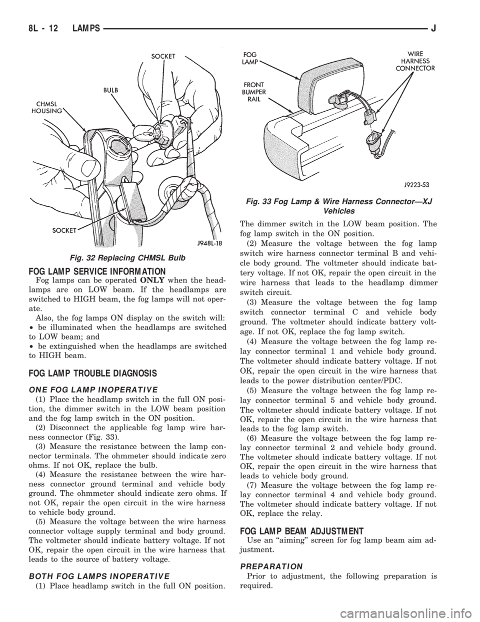
ness connector (Fig. 33).
(3) Measure the resistance between the lamp con-
nector terminals. The ohmmeter should indicate zero
ohms. If not OK, replace the bulb.
(4) Measure the resistance between the wire har-
ness connector ground terminal and vehicle body
ground. The ohmmeter should indicate zero ohms. If
not OK, repair the open circuit in the wire harness
to vehicle body ground.
(5) Measure the voltage between the wire harness
connector voltage supply terminal and body ground.
The voltmeter should indicate battery voltage. If not
OK, repair the open circuit in the wire harness that
leads to the source of battery voltage.
BOTH FOG LAMPS INOPERATIVE
(1) Place headlamp switch in the full ON position.The dimmer switch in the LOW beam position. The
fog lamp switch in the ON position.
(2) Measure the voltage between the fog lamp
switch wire harness connector terminal B and vehi-
cle body ground. The voltmeter should indicate bat-
tery voltage. If not OK, repair the open circuit in the
wire harness that leads to the headlamp dimmer
switch circuit.
(3) Measure the voltage between the fog lamp
switch connector terminal C and vehicle body
ground. The voltmeter should indicate battery volt-
age. If not OK, replace the fog lamp switch.
(4) Measure the voltage between the fog lamp re-
lay connector terminal 1 and vehicle body ground.
The voltmeter should indicate battery voltage. If not
OK, repair the open circuit in the wire harness that
leads to the power distribution center/PDC.
(5) Measure the voltage between the fog lamp re-
lay connector terminal 5 and vehicle body ground.
The voltmeter should indicate battery voltage. If not
OK, repair the open circuit in the wire harness that
leads to the fog lamp switch.
(6) Measure the voltage between the fog lamp re-
lay connector terminal 2 and vehicle body ground.
The voltmeter should indicate battery voltage. If not
OK, repair the open circuit in the wire harness that
leads to vehicle body ground.
(7) Measure the voltage between the fog lamp re-
lay connector terminal 4 and vehicle body ground.
The voltmeter should indicate battery voltage. If not
OK, replace the relay.
FOG LAMP BEAM ADJUSTMENT
Use an ``aiming'' screen for fog lamp beam aim ad-
justment.
PREPARATION
Prior to adjustment, the following preparation is
required.
Fig. 32 Replacing CHMSL Bulb
Fig. 33 Fog Lamp & Wire Harness ConnectorÐXJ
Vehicles
8L - 12 LAMPSJ
Page 864 of 1784
INSPECTION
Inspect for cracks in the combustion chambers and
valve ports.
Inspect for cracks on the exhaust seat.
Inspect for cracks in the gasket surface at each
coolant passage.
Inspect valves for burned, cracked or warped heads.
Inspect for scuffed or bent valve stems.
Replace valves displaying any damage.
VALVE REFACING
(1) Use a valve refacing machine to reface the in-
take and exhaust valves to the specified angle.
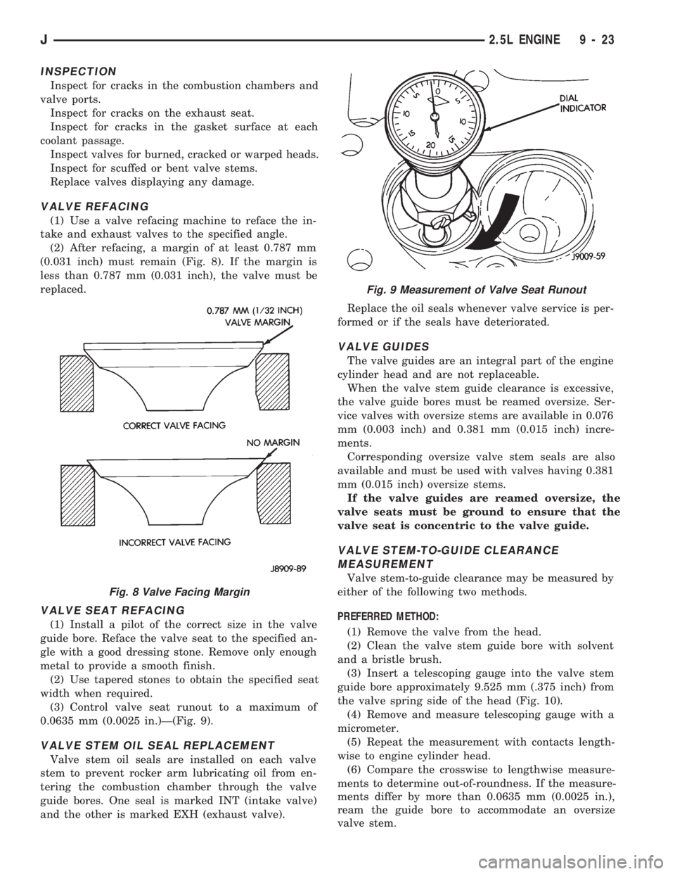
(2) After refacing, a margin of at least 0.787 mm
(0.031 inch) must remain (Fig. 8). If the margin is
less than 0.787 mm (0.031 inch), the valve must be
replaced.
VALVE SEAT REFACING
(1) Install a pilot of the correct size in the valve
guide bore. Reface the valve seat to the specified an-
gle with a good dressing stone. Remove only enough
metal to provide a smooth finish.
(2) Use tapered stones to obtain the specified seat
width when required.
(3) Control valve seat runout to a maximum of
0.0635 mm (0.0025 in.)Ð(Fig. 9).
VALVE STEM OIL SEAL REPLACEMENT
Valve stem oil seals are installed on each valve
stem to prevent rocker arm lubricating oil from en-
tering the combustion chamber through the valve
guide bores. One seal is marked INT (intake valve)
and the other is marked EXH (exhaust valve).Replace the oil seals whenever valve service is per-
formed or if the seals have deteriorated.
VALVE GUIDES
The valve guides are an integral part of the engine
cylinder head and are not replaceable.
When the valve stem guide clearance is excessive,
the valve guide bores must be reamed oversize. Ser-
vice valves with oversize stems are available in 0.076
mm (0.003 inch) and 0.381 mm (0.015 inch) incre-
ments.
Corresponding oversize valve stem seals are also
available and must be used with valves having 0.381
mm (0.015 inch) oversize stems.
If the valve guides are reamed oversize, the
valve seats must be ground to ensure that the
valve seat is concentric to the valve guide.
VALVE STEM-TO-GUIDE CLEARANCE
MEASUREMENT
Valve stem-to-guide clearance may be measured by
either of the following two methods.
PREFERRED METHOD:
(1) Remove the valve from the head.
(2) Clean the valve stem guide bore with solvent
and a bristle brush.
(3) Insert a telescoping gauge into the valve stem
guide bore approximately 9.525 mm (.375 inch) from
the valve spring side of the head (Fig. 10).
(4) Remove and measure telescoping gauge with a
micrometer.
(5) Repeat the measurement with contacts length-
wise to engine cylinder head.
(6) Compare the crosswise to lengthwise measure-
ments to determine out-of-roundness. If the measure-
ments differ by more than 0.0635 mm (0.0025 in.),
ream the guide bore to accommodate an oversize
valve stem.
Fig. 8 Valve Facing Margin
Fig. 9 Measurement of Valve Seat Runout
J2.5L ENGINE 9 - 23
Page 904 of 1784
INSTALLATION
CAUTION: Install oil seals carefully to prevent dam-
age from the sharp edges of the valve spring lock
grove.
(1) Lightly push the valve seal over the valve stem
and valve guide boss. Be sure the seal is completely
seated on the valve guide boss.
(2) Install valve spring and retainer.
(3) Compress the valve spring with Valve Spring
Compressor Tool MD-998772A and insert the valve
locks. Release the spring tension and remove the
tool. Tap the spring from side-to-side to ensure that
the spring is seated properly on the engine cylinder
head.
(4) Disconnect the air hose. Remove the adaptor
from the spark plug hole and install the spark plug.
(5) Repeat the procedures for each remaining valve
spring to be removed.
(6) Install the push rods. Ensure the bottom end of
each rod is centered in the plunger cap seat of the
hydraulic valve tappet.
(7) Install the rocker arms, pivots and bridge at
their original location.
(8) Tighten the bridge capscrews alternately, one
at a time, to avoid damaging the bridge. Tighten the
capscrews to 28 Nzm (21 ft. lbs.) torque.
(9) Install the engine cylinder head cover.
VALVES AND VALVE SPRINGS
This procedure is done with the engine cylinder
head removed from the block.
REMOVAL
(1) Remove the engine cylinder head from the cyl-
inder block.
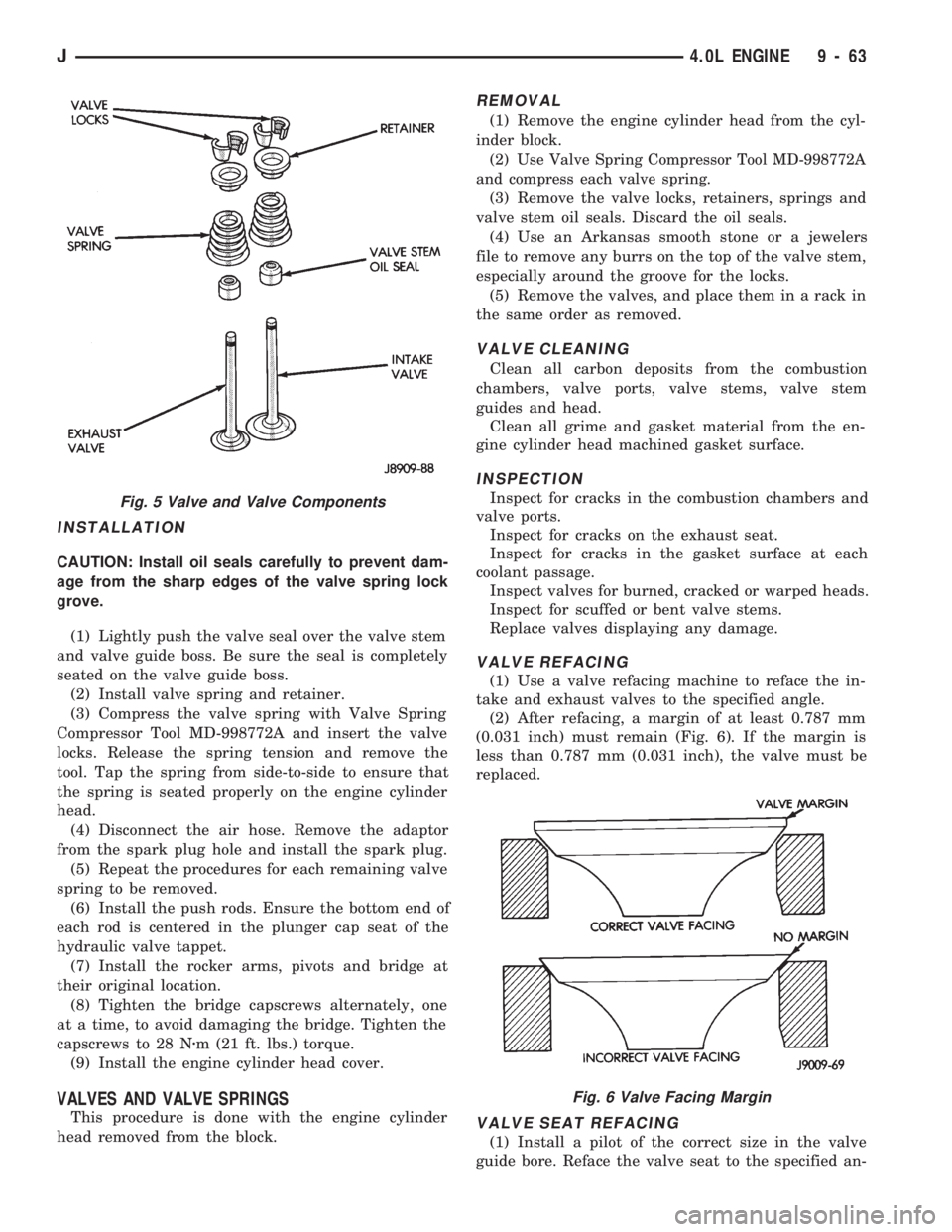
(2) Use Valve Spring Compressor Tool MD-998772A
and compress each valve spring.
(3) Remove the valve locks, retainers, springs and
valve stem oil seals. Discard the oil seals.
(4) Use an Arkansas smooth stone or a jewelers
file to remove any burrs on the top of the valve stem,
especially around the groove for the locks.
(5) Remove the valves, and place them in a rack in
the same order as removed.
VALVE CLEANING
Clean all carbon deposits from the combustion
chambers, valve ports, valve stems, valve stem
guides and head.
Clean all grime and gasket material from the en-
gine cylinder head machined gasket surface.
INSPECTION
Inspect for cracks in the combustion chambers and
valve ports.
Inspect for cracks on the exhaust seat.
Inspect for cracks in the gasket surface at each
coolant passage.
Inspect valves for burned, cracked or warped heads.
Inspect for scuffed or bent valve stems.
Replace valves displaying any damage.
VALVE REFACING
(1) Use a valve refacing machine to reface the in-
take and exhaust valves to the specified angle.
(2) After refacing, a margin of at least 0.787 mm
(0.031 inch) must remain (Fig. 6). If the margin is
less than 0.787 mm (0.031 inch), the valve must be
replaced.
VALVE SEAT REFACING
(1) Install a pilot of the correct size in the valve
guide bore. Reface the valve seat to the specified an-
Fig. 5 Valve and Valve Components
Fig. 6 Valve Facing Margin
J4.0L ENGINE 9 - 63
Page 969 of 1784
pressure is bleeding past the (in-tank mounted) fuel
pump outlet check valve. Replace Fuel Pump Module
assembly. Refer to Fuel Pump Module removal and
installation in this group. If pressure drop is within
specifications, proceed to next step.
(13) Clamp off the rubber hose portion of adapter
tool number 6631 connected to the fuel supply line.
Allow engine to set for 30 minutes. If pressure has
dropped more than 138 kPa (20 psi) in 30 minutes,
pressure is bleeding past the fuel pressure regulator.
Replace fuel pressure regulator. Refer to Fuel Rail
removal and installation in the Component Removal/
Installation section of this group.
MECHANICAL MALFUNCTIONS
Mechanical malfunctions are more difficult to diag-
nose with this system. The powertrain control mod-
ule (PCM) has been programmed to compensate for
some mechanical malfunctions such as incorrect cam
timing, vacuum leaks, etc. If engine performance
problems are encountered and diagnostic trouble
codes are not displayed, the problem may be mechan-
ical rather than electronic.
FUEL FILTER
The fuel filter protects the fuel injectors and fuel
pressure regulator from dirt, water and other foreign
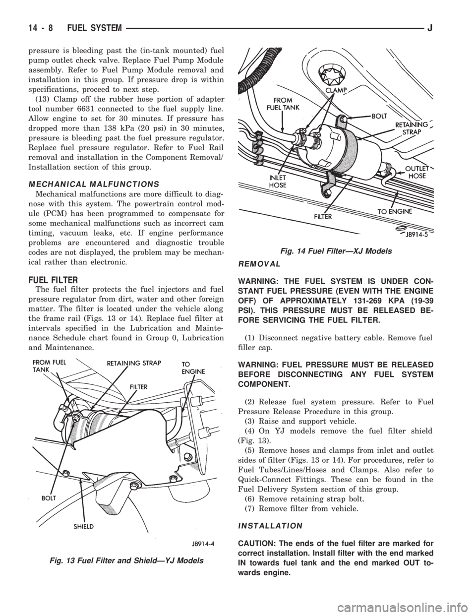
matter. The filter is located under the vehicle along
the frame rail (Figs. 13 or 14). Replace fuel filter at
intervals specified in the Lubrication and Mainte-
nance Schedule chart found in Group 0, Lubrication
and Maintenance.
REMOVAL
WARNING: THE FUEL SYSTEM IS UNDER CON-
STANT FUEL PRESSURE (EVEN WITH THE ENGINE
OFF) OF APPROXIMATELY 131-269 KPA (19-39
PSI). THIS PRESSURE MUST BE RELEASED BE-
FORE SERVICING THE FUEL FILTER.
(1) Disconnect negative battery cable. Remove fuel
filler cap.
WARNING: FUEL PRESSURE MUST BE RELEASED
BEFORE DISCONNECTING ANY FUEL SYSTEM
COMPONENT.
(2) Release fuel system pressure. Refer to Fuel
Pressure Release Procedure in this group.
(3) Raise and support vehicle.
(4) On YJ models remove the fuel filter shield
(Fig. 13).
(5) Remove hoses and clamps from inlet and outlet
sides of filter (Figs. 13 or 14). For procedures, refer to
Fuel Tubes/Lines/Hoses and Clamps. Also refer to
Quick-Connect Fittings. These can be found in the
Fuel Delivery System section of this group.
(6) Remove retaining strap bolt.
(7) Remove filter from vehicle.
INSTALLATION
CAUTION: The ends of the fuel filter are marked for
correct installation. Install filter with the end marked
IN towards fuel tank and the end marked OUT to-
wards engine.
Fig. 13 Fuel Filter and ShieldÐYJ Models
Fig. 14 Fuel FilterÐXJ Models
14 - 8 FUEL SYSTEMJ