1994 JEEP CHEROKEE display
[x] Cancel search: displayPage 137 of 1784
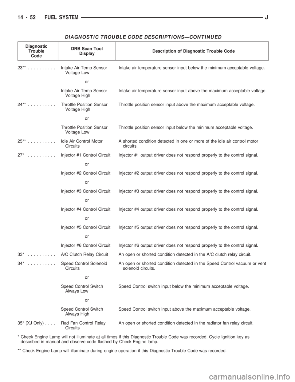
DIAGNOSTIC TROUBLE CODE DESCRIPTIONSÐCONTINUED
Diagnostic
Trouble
CodeDRB Scan Tool
DisplayDescription of Diagnostic Trouble Code
23**..........Intake Air Temp Sensor
Voltage LowIntake air temperature sensor input below the minimum acceptable voltage.
or
Intake Air Temp Sensor
Voltage HighIntake air temperature sensor input above the maximum acceptable voltage.
24**..........Throttle Position Sensor
Voltage HighThrottle position sensor input above the maximum acceptable voltage.
or
Throttle Position Sensor
Voltage LowThrottle position sensor input below the minimum acceptable voltage.
25**..........Idle Air Control Motor
CircuitsA shorted condition detected in one or more of the idle air control motor
circuits.
27* ..........Injector #1 Control Circuit Injector #1 output driver does not respond properly to the control signal.
or
Injector #2 Control Circuit Injector #2 output driver does not respond properly to the control signal.
or
Injector #3 Control Circuit Injector #3 output driver does not respond properly to the control signal.
or
Injector #4 Control Circuit Injector #4 output driver does not respond properly to the control signal.
or
Injector #5 Control Circuit Injector #5 output driver does not respond properly to the control signal.
or
Injector #6 Control Circuit Injector #6 output driver does not respond properly to the control signal.
33* .......... A/CClutch Relay Circuit An open or shorted condition detected in the A/C clutch relay circuit.
34* ..........Speed Control Solenoid
CircuitsAn open or shorted condition detected in the Speed Control vacuum or vent
solenoid circuits.
or
Speed Control Switch
Always LowSpeed Control switch input below the minimum acceptable voltage.
or
Speed Control Switch
Always HighSpeed Control switch input above the maximum acceptable voltage.
35* (XJ Only).... RadFanControl Relay
CircuitsAn open or shorted condition detected in the radiator fan relay circuit.
* Check Engine Lamp will not illuminate at all times if this Diagnostic Trouble Code was recorded. Cycle Ignition key as
described in manual and observe code flashed by Check Engine lamp.
** Check Engine Lamp will illuminate during engine operation if this Diagnostic Trouble Code was recorded.
14 - 52 FUEL SYSTEMJ
Page 138 of 1784
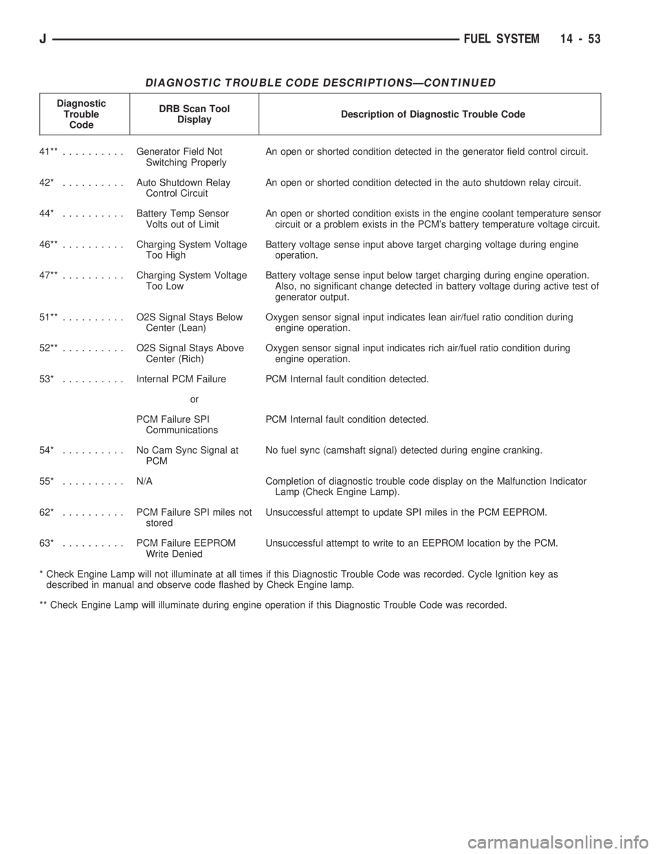
DIAGNOSTIC TROUBLE CODE DESCRIPTIONSÐCONTINUED
Diagnostic
Trouble
CodeDRB Scan Tool
DisplayDescription of Diagnostic Trouble Code
41**..........Generator Field Not
Switching ProperlyAn open or shorted condition detected in the generator field control circuit.
42* ..........Auto Shutdown Relay
Control CircuitAn open or shorted condition detected in the auto shutdown relay circuit.
44* ..........Battery Temp Sensor
Volts out of LimitAn open or shorted condition exists in the engine coolant temperature sensor
circuit or a problem exists in the PCM's battery temperature voltage circuit.
46**..........Charging System Voltage
Too HighBattery voltage sense input above target charging voltage during engine
operation.
47**..........Charging System Voltage
Too LowBattery voltage sense input below target charging during engine operation.
Also, no significant change detected in battery voltage during active test of
generator output.
51**.......... O2SSignal Stays Below
Center (Lean)Oxygen sensor signal input indicates lean air/fuel ratio condition during
engine operation.
52**.......... O2SSignal Stays Above
Center (Rich)Oxygen sensor signal input indicates rich air/fuel ratio condition during
engine operation.
53* ..........Internal PCM Failure PCM Internal fault condition detected.
or
PCM Failure SPI
CommunicationsPCM Internal fault condition detected.
54* .......... NoCamSync Signal at
PCMNo fuel sync (camshaft signal) detected during engine cranking.
55* .......... N/ACompletion of diagnostic trouble code display on the Malfunction Indicator
Lamp (Check Engine Lamp).
62* .......... PCMFailure SPI miles not
storedUnsuccessful attempt to update SPI miles in the PCM EEPROM.
63* .......... PCMFailure EEPROM
Write DeniedUnsuccessful attempt to write to an EEPROM location by the PCM.
* Check Engine Lamp will not illuminate at all times if this Diagnostic Trouble Code was recorded. Cycle Ignition key as
described in manual and observe code flashed by Check Engine lamp.
** Check Engine Lamp will illuminate during engine operation if this Diagnostic Trouble Code was recorded.
JFUEL SYSTEM 14 - 53
Page 150 of 1784
ABS BRAKE DIAGNOSIS
INDEX
page page
ABS Fault Diagnosis....................... 4
ABS System Wiring and Electrical Circuits...... 4
ABS Warning Light Display.................. 3
Brake Warning Light Display................. 4
Diagnosis Procedures...................... 3
ECU Diagnosis........................... 4
HCU Diagnosis........................... 4Loss of Sensor Input....................... 3
Operating Sound Levels.................... 3
Rear Speed Sensor Air Gap................. 3
Steering Response........................ 3
Vehicle Response in Antilock Mode............ 3
Wheel/Tire Size and Input Signals............. 3
DIAGNOSIS PROCEDURES
ABS diagnosis involves three basic steps. First is
observation of the warning light display. Second is a
visual examination for low fluid level, leaks, parking
brakes applied, or obvious damage to system compo-
nents or wires. The third step involves using the
DRB II scan tool to identify a faulty component.
The visual examination requires a check of reser-
voir fluid level and all system components. Things to
look for are leaks, loose connections, or obvious com-
ponent damage.
The final diagnosis step involves using the DRB II
scan tool to determine the specific circuit or compo-
nent at fault. The tester is connected to the ABS di-
agnostic connector in the passenger compartment.
The connector is at the driver side of the center con-
sole under the instrument panel. Refer to the DRB II
scan tool Manual for tester procedures. Also refer to
the ABS Fault Diagnosis charts at the end of this
section for additional diagnosis information.
Initial faults should be cleared and the vehicle road
tested to reset any faults that remain in the system.
Faults can be cleared with the DRB II scan tool.
REAR SPEED SENSOR AIR GAP
The front wheel sensors are fixed and cannot be ad-
justed. Only the rear sensor air gap is adjustable. Air
gap must be set with a brass feeler gauge.
Correct air gap is important to proper signal gen-
eration. An air gap that is too large may cause com-
plete loss of sensor input. Or, a gap that is too small
could produce a false input signal, or damaging con-
tact between the sensor and tone ring.
WHEEL/TIRE SIZE AND INPUT SIGNALS
Antilock system operation is dependant on accurate
signals from the wheel speed sensors. Ideally, the ve-
hicle wheels and tires should all be the same size
and type. However, the Jeep ABS system is designed
to function with a compact spare tire installed.
OPERATING SOUND LEVELS
The ABS pump and solenoid valves may produce
some sound as they cycle on and off. This is a normal
condition and should not be mistaken for faulty oper-
ation.
VEHICLE RESPONSE IN ANTILOCK MODE
During antilock braking, the HCU solenoid valves
cycle rapidly in response to ECU inputs.
The driver will experience a pulsing sensation
within the vehicle as the solenoids decrease, hold, or
increase pressure as needed. A pulsing brake pedal
will also be noted.
The pulsing sensation occurs as the solenoids cycle
during antilock mode braking. A slight pulse in the
brake pedal may also be noted during the dynamic
self check part of system initialization.
STEERING RESPONSE
A modest amount of steering input is required dur-
ing extremely high deceleration braking, or when
braking on differing traction surfaces. An example of
differing traction surfaces would be when the left
side wheels are on ice and the right side wheels are
on dry pavement.
LOSS OF SENSOR INPUT
Sensor malfunctions will most likely be due to
loose connections, damaged sensor wires, incorrect
rear sensor air gap, or a malfunctioning sensor. Ad-
ditional causes of sensor faults would be sensor and
tone ring misalignment or damage.
ABS WARNING LIGHT DISPLAY
ABS Light Illuminates At Startup
The amber ABS light illuminates at startup as
part of the system self check feature. The light illu-
minates for 2-3 seconds then goes off as part of the
normal self check routine.
ABS Light Remains On After Startup
An ABS system fault is indicated when the light
remains on after startup. Diagnosis with the DRB II
JBRAKES 5 - 3
Page 151 of 1784

scan tool will be necessary to determine which ABS
component has malfunctioned.
ABS Light Illuminates During Brake Stop
A system fault such as loss of speed sensor signal
or solenoid failure, will cause the amber warning
light to illuminate. The most effective procedure here
is to check for obvious damage first. Then check the
electronic components with the DRB II scan tool.
BRAKE WARNING LIGHT DISPLAY
The red brake warning light and the ABS light op-
erate independently. If the red light remains on after
startup or illuminates during a brake stop, refer to
the standard brake system diagnosis section. Either
the parking brakes are applied, or a wheel brake
malfunction has occurred.
ECU DIAGNOSIS
The ECU controls all phases of antilock system op-
eration. It also differentiates between normal and an-
tilock mode braking.
The ECU monitors and processes the signals gen-
erated from all of the system sensors at all times.
The ECU program includes a self check routine
that tests each of the system components. The self
check occurs during both phases of the initialization
program. A failure of the self check program will
cause the immediate illumination of the amber warn-
ing light. The light will also illuminate if a solenoid
or other system component fails during the dynamic
phase of initialization.
If a system malfunction should occur, do not imme-
diately replace the ECU. A blown system fuse, bad
chassis ground, or loss of feed voltage will each cause
a system malfunction similar to an ECU failure.
Never replace the ECU unless diagnosis with the
DRB II scan tool indicates this is necessary.
HCU DIAGNOSIS
The HCU pump and motor and solenoid valve body
are serviced only as an assembly. The HCU assembly
should not be replaced unless a fault has actually
been confirmed. Verify fault conditions with the DRB
II scan tool before proceeding with repair.
ABS SYSTEM WIRING AND ELECTRICAL CIRCUITS
Location of the ABS fuse (in the fuse panel) is
shown in Figure 1. The engine compartment harness
routing for the ABS components is shown in Figure 2.
ABS FAULT DIAGNOSIS
The fault diagnosis chart provides additional infor-
mation on potential ABS system faults. Use the
chart as a guide when diagnosing a system problem.
Fig. 1 ABS Fuse Location
5 - 4 BRAKESJ
Page 237 of 1784
DIAGNOSIS
INDEX
page page
DRB Scan Tool........................... 5
On-Board Diagnostics (OBD)................. 4Preliminary Checks........................ 5
ON-BOARD DIAGNOSTICS (OBD)
FOR COOLING SYSTEM COMPONENTS
The powertrain control module (PCM) has been
programmed to monitor the certain following cooling
system components:
²If the engine has remained cool for too long a pe-
riod, such as with a stuck open thermostat, a Diag-
nostic Trouble Code (DTC) number 17 can be
observed at the Check Engine Lamp.
²If an open or shorted condition has developed in
the relay circuit controlling the electric radiator fan,
a Diagnostic Trouble Code (DTC) number 35 can be
observed at the Check Engine Lamp.
If the problem is sensed in a monitored circuit of-
ten enough to indicate an actual problem, a DTC is
stored. The DTC will be stored in the PCM memory
for eventual display to the service technician. If the
problem is repaired or ceases to exist, the PCM can-
cels the DTC after 51 engine starts.
Certain criteria must be met for a DTC to be en-
tered into PCM memory. The criteria may be a spe-
cific range of engine rpm, engine temperature and/or
input voltage to the PCM.
A DTC indicates that the PCM has recognized an
abnormal signal in a circuit or the system. A DTC
may indicate the result of a failure, but never iden-
tify the failed component directly.
It is possible that a DTC for a monitored circuit
may not be entered into memory even though a mal-
function has occurred. Refer to On-Board Diagnostics
(OBD) in Group 14, Fuel Systems for additional in-
formation.
ACCESSING DIAGNOSTIC TROUBLE CODES
A stored Diagnostic Trouble Code (DTC) can be dis-
played by cycling the ignition key On-Off-On-Off-On
within three seconds and observing the Malfunction
Indicator Lamp. This lamp was formerly referred to
as the Check Engine Lamp. The lamp is located on
the instrument panel.
They can also be displayed through the use of the
Diagnostic Readout Box (DRB) scan tool. The DRB
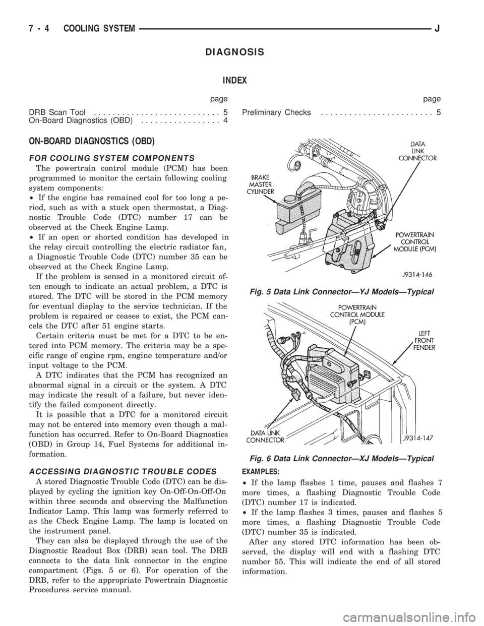
connects to the data link connector in the engine
compartment (Figs. 5 or 6). For operation of the
DRB, refer to the appropriate Powertrain Diagnostic
Procedures service manual.EXAMPLES:
²If the lamp flashes 1 time, pauses and flashes 7
more times, a flashing Diagnostic Trouble Code
(DTC) number 17 is indicated.
²If the lamp flashes 3 times, pauses and flashes 5
more times, a flashing Diagnostic Trouble Code
(DTC) number 35 is indicated.
After any stored DTC information has been ob-
served, the display will end with a flashing DTC
number 55. This will indicate the end of all stored
information.
Fig. 5 Data Link ConnectorÐYJ ModelsÐTypical
Fig. 6 Data Link ConnectorÐXJ ModelsÐTypical
7 - 4 COOLING SYSTEMJ
Page 292 of 1784
USING ON-BOARD DIAGNOSTIC SYSTEM
OPERATION OF ON-BOARD DIAGNOSTIC
(OBD) SYSTEM
The Powertrain Control Module (PCM) monitors
critical input and output circuits of the charging sys-
tem making sure they are OK. Some are checked
continuously and some are checked only under cer-
tain conditions.
If OBD system senses that one critical circuit is
bad during the monitoring cycle, it will put a diag-
nostic trouble code into memory. Each input and out-
put circuit monitored by the OBD system has its own
diagnostic trouble code. The diagnostic trouble code
(DTC) will stay in memory as long as the circuit con-
tinues to be bad. If the problem does not happen
again after the fault code is put into memory, the
PCM is programmed to clear the memory after 50 en-
gine starts.
DIAGNOSTIC TROUBLE CODES (DTC)
Diagnostic trouble codes are two-digit numbers
flashed on Malfunction Indicator (Check Engine)
Lamp that identify which circuit is bad. In most
cases they do not identify which component in a cir-
cuit is bad. A trouble code description can be read us-
ing the DRB scan tool. Refer to Group 14 - Fuel
Systems for more information. Therefore, a DTC is
only a symptom, not necessarily the cause for the
problem. In some cases, because of the design of the
driveability test procedure, a DTC can be the reason
for the problem. It is important that the test proce-
dure be followed to understand what caused the DTC
of the on-board diagnostic system to be set.
HOW TO USE MALFUNCTION INDICATOR (CHECK
ENGINE) LAMP FOR DIAGNOSTIC TROUBLE
CODES
To start this function, cycle the ignition switch ON-
OFF-ON-OFF-ON within 5 seconds and any trouble
code stored in the PCM will be displayed. The Mal-
function Indicator (Check Engine) Lamp will display
a DTC by flashing on and off. There is a short pause
between flashes and a longer pause between digits.
All codes displayed are two digit numbers with a 4
second pause between codes.
An example of a code is as follows:
(1) Lamp on for 2 seconds, then turns off.
(2) Lamp flashes 4 times pauses and then flashes 1
time.
(3) Lamp pauses for 4 seconds, flashes 4 times,
pauses and then flashes 7 times.
The 2 codes are 41 and 47. Any number of codes
can be displayed as long as they are in memory. The
lamp will flash until all are displayed (55 = End of
test).
CHARGING SYSTEM DIAGNOSTIC TROUBLE
CODES
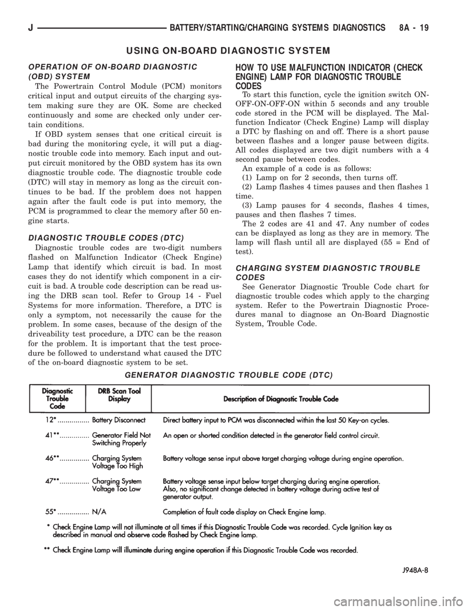
See Generator Diagnostic Trouble Code chart for
diagnostic trouble codes which apply to the charging
system. Refer to the Powertrain Diagnostic Proce-
dures manal to diagnose an On-Board Diagnostic
System, Trouble Code.
GENERATOR DIAGNOSTIC TROUBLE CODE (DTC)
JBATTERY/STARTING/CHARGING SYSTEMS DIAGNOSTICS 8A - 19
Page 306 of 1784

OVERHEAD CONSOLE
CONTENTS
page page
COMPASS REPAIR PROCEDURES.......... 4
CONSOLE REPAIR PROCEDURES........... 6
DESCRIPTION........................... 1DIAGNOSTIC PROCEDURES............... 1
THERMOMETER AND SENSOR SYSTEM REPAIR
PROCEDURES......................... 6
DESCRIPTION
The overhead console includes:
²a compass/temperature display
²reading and courtesy lights for the front and rear
seats
²the receiver for the keyless entry system
²storage compartment for remote garage door
opener
²storage compartment for sunglasses.
COMPASS
The compass will display the direction the vehicle
is pointed, using the eight major compass headings
(Examples: North is ``N'', Northeast is ``NE''). It does
not display the headings in actual degrees. The dis-
play is turned on/off using the TEMP/COMP button
on the left of the display.
The compass is a self calibrating unit that should
not require recalibration. The only calibration that
may prove necessary is to drive the vehicle in 3 com-
plete circles, on level ground, in not less than 48 sec-
onds. This will ``reorient'' the unit to its vehicle. The
unit also will compensate for magnetism the vehicle
may acquire during its life. Care should be used to
avoid putting anything magnetic on the roof of the
vehicle.
The unit can compensate for some magnetic fields
in the body. The use of magnetic attachments like
antenna mounts or repair order ``hats'' placed di-
rectly on the roof can exceed the compensation abil-
ity of the unit. Magnetic bit drivers used on the
fasteners to hold the assembly to the roof header can
also affect operation. If the vehicle roof should be-
come magnetized, then the degaussing and calibra-
tion procedures may be required to restore proper
operation.
If the compass functions but accuracy is suspect, it
may be necessary to perform a variation adjustment.
This procedure allows the unit to accommodate vari-
ations in the earth's magnetic field strength based on
geographic location.
If the compass has blanked out and only CAL
appears, degaussing may be necessary to re-
move residual magnetic fields.
THERMOMETER
The ambient temperature display can be changed
from Fahrenheit to Celsius using the U.S./METRIC
button on the right of the display. The temperature
reported is not an instant reading of conditions but
an average temperature. It may take the unit several
minutes to react to a major change such as driving
out of a heated garage into winter temperatures.
When the ignition switch is turned OFF, the last
displayed temperature reading stays in memory.
When the ignition switch is turned ON again the
thermometer will display the memory temperature
for one minute; then update the display to the actual
temperature within five minutes.
READING AND COURTESY LAMPS
All reading and courtesy lamps in the overhead
console are activated by the door courtesy circuit.
When all four doors and the liftgate are closed the
lamps can be activated by depressing the correspond-
ing lens. When any door or the liftgate is open, the
switches are disabled. They will not turn the lamps
off.
MAP AND COURTESY LAMPS
These lamps offer several unique features. Both the
map and courtesy lamps can be turned on with the
integral ``Soft Touch'' switch. Pushing this switch en-
ergizes an electrical circuit, which in turn directs
power to the light. The map lamps are unaffected by
the door switches, while the courtesy lamps are
turned on with the opening of any door. When any
door is open, the ``Soft Touch'' switches are disabled,
you cannot turn the lights off with these switches.
DIAGNOSTIC PROCEDURES
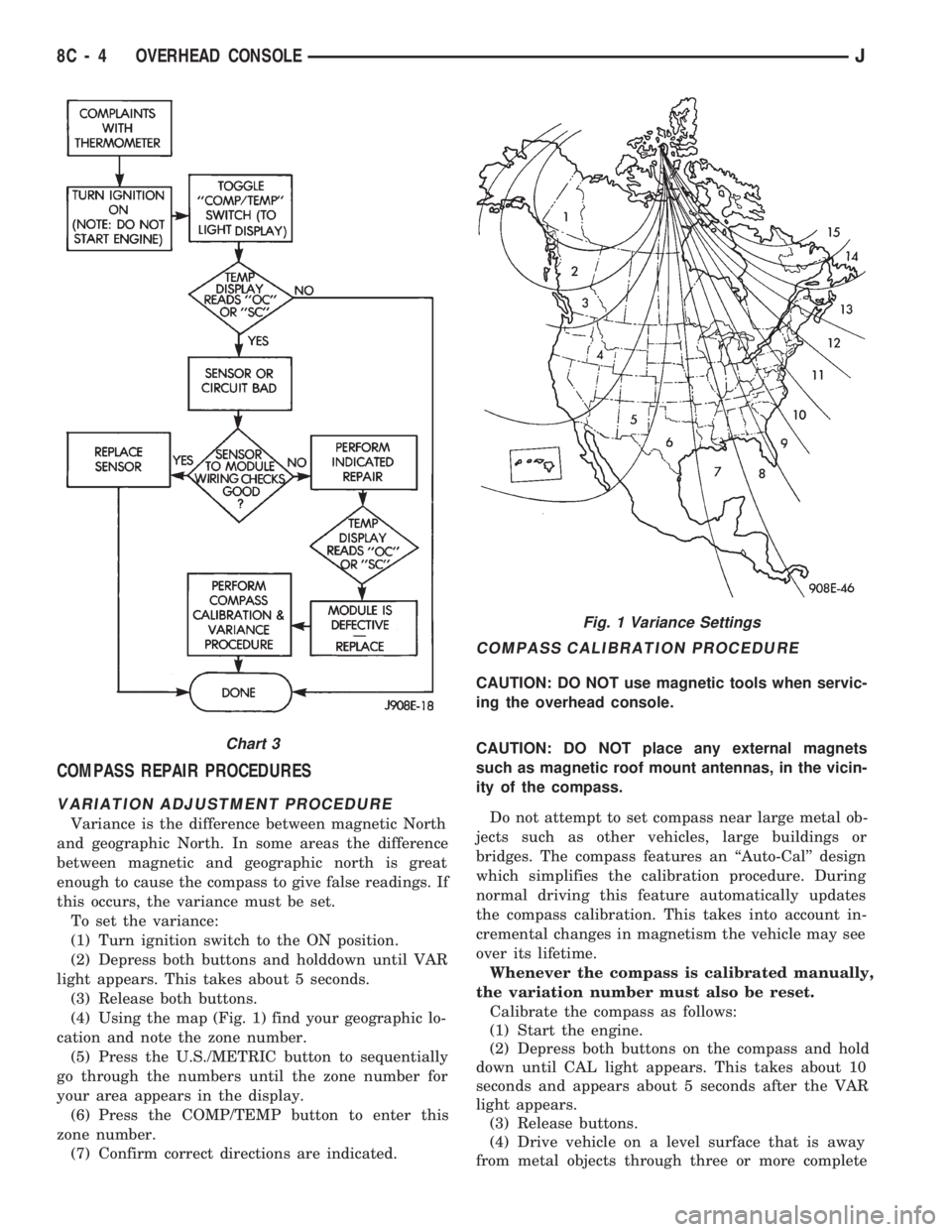
Follow the appropriate diagnostic flow chart:
²Chart 1 describes the procedures for compass and
display problems.
²Chart 2 describes the procedures for illumination
lamp problems.
²Chart 3 describes the procedures for outside tem-
perature measuring problems.
JOVERHEAD CONSOLE 8C - 1
Page 309 of 1784
COMPASS REPAIR PROCEDURES
VARIATION ADJUSTMENT PROCEDURE
Variance is the difference between magnetic North
and geographic North. In some areas the difference
between magnetic and geographic north is great
enough to cause the compass to give false readings. If
this occurs, the variance must be set.
To set the variance:
(1) Turn ignition switch to the ON position.
(2) Depress both buttons and holddown until VAR
light appears. This takes about 5 seconds.
(3) Release both buttons.
(4) Using the map (Fig. 1) find your geographic lo-
cation and note the zone number.
(5) Press the U.S./METRIC button to sequentially
go through the numbers until the zone number for
your area appears in the display.
(6) Press the COMP/TEMP button to enter this
zone number.
(7) Confirm correct directions are indicated.
COMPASS CALIBRATION PROCEDURE
CAUTION: DO NOT use magnetic tools when servic-
ing the overhead console.
CAUTION: DO NOT place any external magnets
such as magnetic roof mount antennas, in the vicin-
ity of the compass.
Do not attempt to set compass near large metal ob-
jects such as other vehicles, large buildings or
bridges. The compass features an ``Auto-Cal'' design
which simplifies the calibration procedure. During
normal driving this feature automatically updates
the compass calibration. This takes into account in-
cremental changes in magnetism the vehicle may see
over its lifetime.
Whenever the compass is calibrated manually,
the variation number must also be reset.
Calibrate the compass as follows:
(1) Start the engine.
(2) Depress both buttons on the compass and hold
down until CAL light appears. This takes about 10
seconds and appears about 5 seconds after the VAR
light appears.
(3) Release buttons.
(4) Drive vehicle on a level surface that is away
from metal objects through three or more complete
Fig. 1 Variance Settings
Chart 3
8C - 4 OVERHEAD CONSOLEJ