1994 JEEP CHEROKEE service
[x] Cancel search: servicePage 1538 of 1784
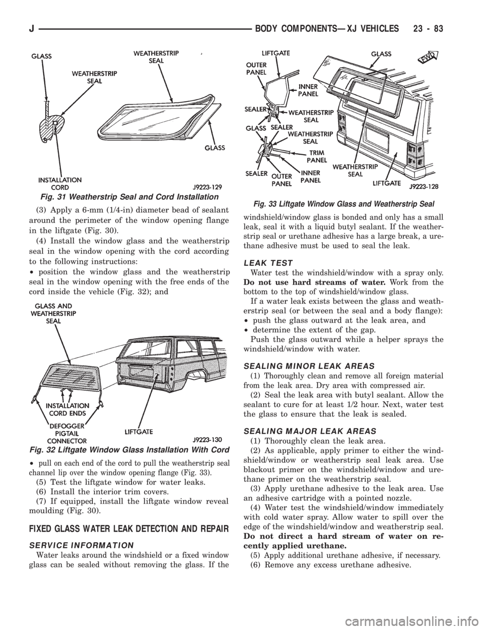
(3) Apply a 6-mm (1/4-in) diameter bead of sealant
around the perimeter of the window opening flange
in the liftgate (Fig. 30).
(4) Install the window glass and the weatherstrip
seal in the window opening with the cord according
to the following instructions:
²position the window glass and the weatherstrip
seal in the window opening with the free ends of the
cord inside the vehicle (Fig. 32); and
²
pull on each end of the cord to pull the weatherstrip seal
channel lip over the window opening flange (Fig. 33).
(5) Test the liftgate window for water leaks.
(6) Install the interior trim covers.
(7) If equipped, install the liftgate window reveal
moulding (Fig. 30).
FIXED GLASS WATER LEAK DETECTION AND REPAIR
SERVICE INFORMATION
Water leaks around the windshield or a fixed window
glass can be sealed without removing the glass. If thewindshield/window glass is bonded and only has a small
leak, seal it with a liquid butyl sealant. If the weather-
strip seal or urethane adhesive has a large break, a ure-
thane adhesive must be used to seal the leak.
LEAK TEST
Water test the windshield/window with a spray only.
Do not use hard streams of water.Work from the
bottom to the top of windshield/window glass.
If a water leak exists between the glass and weath-
erstrip seal (or between the seal and a body flange):
²push the glass outward at the leak area, and
²determine the extent of the gap.
Push the glass outward while a helper sprays the
windshield/window with water.
SEALING MINOR LEAK AREAS
(1) Thoroughly clean and remove all foreign material
from the leak area. Dry area with compressed air.
(2) Seal the leak area with butyl sealant. Allow the
sealant to cure for at least 1/2 hour. Next, water test
the glass to ensure that the leak is sealed.
SEALING MAJOR LEAK AREAS
(1) Thoroughly clean the leak area.
(2) As applicable, apply primer to either the wind-
shield/window or weatherstrip seal leak area. Use
blackout primer on the windshield/window and ure-
thane primer on the weatherstrip seal.
(3) Apply urethane adhesive to the leak area. Use
an adhesive cartridge with a pointed nozzle.
(4) Water test the windshield/window immediately
with cold water spray. Allow water to spill over the
edge of the windshield/window and weatherstrip seal.
Do not direct a hard stream of water on re-
cently applied urethane.
(5) Apply additional urethane adhesive, if necessary.
(6) Remove any excess urethane adhesive.
Fig. 31 Weatherstrip Seal and Cord Installation
Fig. 32 Liftgate Window Glass Installation With Cord
Fig. 33 Liftgate Window Glass and Weatherstrip Seal
JBODY COMPONENTSÐXJ VEHICLES 23 - 83
Page 1539 of 1784
UNDERBODY COMPONENTS
INDEX
page page
Catalytic Converter/Muffler/Tailpipe Support
Brackets............................. 85
Front Skid Plate......................... 84
Fuel and Brake Fluid Tube Retainer Clip....... 86
Fuel Filler Hose Splash ShieldÐXJ Vehicles.... 86
Fuel Filter Bracket........................ 86Fuel Tank Skid Plate...................... 84
Fuel Tank Support Strap................... 86
Rear Tow HookÐXJ Vehicles............... 87
Service Information....................... 84
Trailer Hitches........................... 88
Transfer Case Skid Plate.................. 84
SERVICE INFORMATION
In some cases, components in the following proce-
dures either support, or are concealed by other com-
ponents. When necessary, refer to component
removal procedure for service access.
FRONT SKID PLATE
REMOVAL
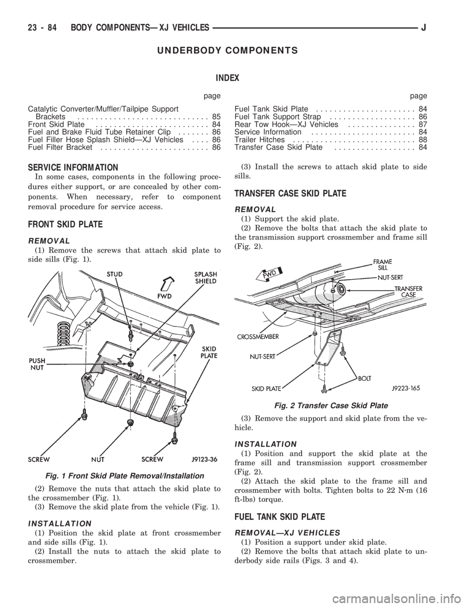
(1) Remove the screws that attach skid plate to
side sills (Fig. 1).
(2) Remove the nuts that attach the skid plate to
the crossmember (Fig. 1).
(3) Remove the skid plate from the vehicle (Fig. 1).
INSTALLATION
(1) Position the skid plate at front crossmember
and side sills (Fig. 1).
(2) Install the nuts to attach the skid plate to
crossmember.(3) Install the screws to attach skid plate to side
sills.
TRANSFER CASE SKID PLATE
REMOVAL
(1) Support the skid plate.
(2) Remove the bolts that attach the skid plate to
the transmission support crossmember and frame sill
(Fig. 2).
(3) Remove the support and skid plate from the ve-
hicle.
INSTALLATION
(1) Position and support the skid plate at the
frame sill and transmission support crossmember
(Fig. 2).
(2) Attach the skid plate to the frame sill and
crossmember with bolts. Tighten bolts to 22 Nzm (16
ft-lbs) torque.
FUEL TANK SKID PLATE
REMOVALÐXJ VEHICLES
(1) Position a support under skid plate.
(2) Remove the bolts that attach skid plate to un-
derbody side rails (Figs. 3 and 4).
Fig. 1 Front Skid Plate Removal/Installation
Fig. 2 Transfer Case Skid Plate
23 - 84 BODY COMPONENTSÐXJ VEHICLESJ
Page 1541 of 1784
(3) Attach catalytic converter, muffler or tailpipe
insulator to support hanger to insulator.
FUEL AND BRAKE FLUID TUBE RETAINER CLIP
REMOVAL
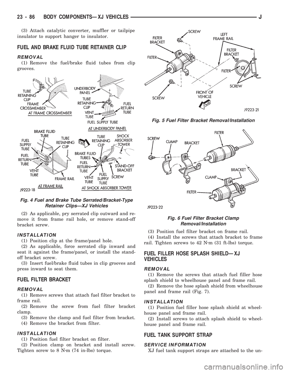
(1) Remove the fuel/brake fluid tubes from clip
grooves.
(2) As applicable, pry serrated clip outward and re-
move it from frame rail hole, or remove stand-off
bracket screw.
INSTALLATION
(1) Position clip at the frame/panel hole.
(2) As applicable, force serrated clip inward and
seat it against the frame/panel, or install the stand-
off bracket screw.
(3) Insert fuel/brake fluid tubes in clip grooves and
press inward to seat them.
FUEL FILTER BRACKET
REMOVAL
(1) Remove screws that attach fuel filter bracket to
frame rail.
(2) Remove the screw from fuel filter bracket
clamp.
(3) Remove the clamp and fuel filter from bracket.
(4) Remove the bracket from filter.
INSTALLATION
(1) Position fuel filter bracket on filter.
(2) Position clamp on bracket and install screw.
Tighten screw to 8 Nzm (74 in-lbs) torque.(3) Position fuel filter bracket on frame rail.
(4) Install the screws that attach bracket to frame
rail. Tighten screws to 42 Nzm (31 ft-lbs) torque.
FUEL FILLER HOSE SPLASH SHIELDÐXJ
VEHICLES
REMOVAL
(1) Remove the screws that attach fuel filler hose
splash shield to wheelhouse panel and frame rail.
(2) Remove the hose splash shield from wheelhouse
panel and frame rail (Fig. 7).
INSTALLATION
(1) Position fuel filler hose splash shield at wheel-
house panel and frame rail.
(2) Install screws to attach splash shield to wheel-
house panel and frame rail.
FUEL TANK SUPPORT STRAP
SERVICE INFORMATION
XJ fuel tank support straps are attached to the un-
Fig. 4 Fuel and Brake Tube Serrated/Bracket-Type
Retainer ClipsÐXJ Vehicles
Fig. 5 Fuel Filter Bracket Removal/Installation
Fig. 6 Fuel Filter Bracket Clamp
Removal/Installation
23 - 86 BODY COMPONENTSÐXJ VEHICLESJ
Page 1561 of 1784
as a unit. Refer to Power Seat Components (below)
and to Group 8ÐElectrical.
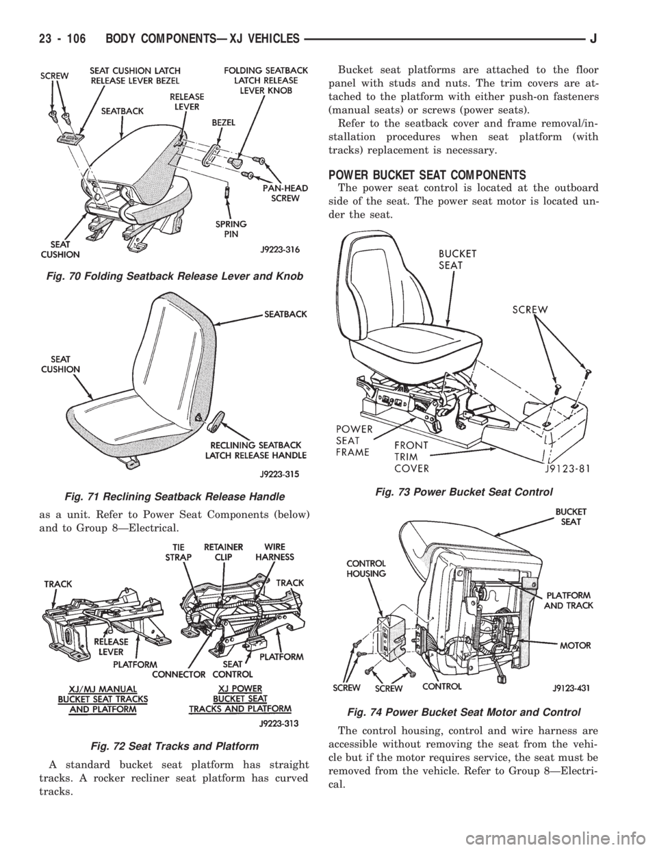
A standard bucket seat platform has straight
tracks. A rocker recliner seat platform has curved
tracks.Bucket seat platforms are attached to the floor
panel with studs and nuts. The trim covers are at-
tached to the platform with either push-on fasteners
(manual seats) or screws (power seats).
Refer to the seatback cover and frame removal/in-
stallation procedures when seat platform (with
tracks) replacement is necessary.
POWER BUCKET SEAT COMPONENTS
The power seat control is located at the outboard
side of the seat. The power seat motor is located un-
der the seat.
The control housing, control and wire harness are
accessible without removing the seat from the vehi-
cle but if the motor requires service, the seat must be
removed from the vehicle. Refer to Group 8ÐElectri-
cal.
Fig. 70 Folding Seatback Release Lever and Knob
Fig. 71 Reclining Seatback Release Handle
Fig. 72 Seat Tracks and Platform
Fig. 73 Power Bucket Seat Control
Fig. 74 Power Bucket Seat Motor and Control
23 - 106 BODY COMPONENTSÐXJ VEHICLESJ
Page 1567 of 1784
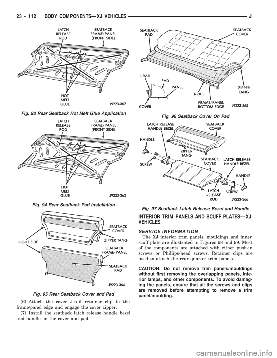
(6) Attach the cover J-rail retainer clip to the
frame/panel edge and engage the cover zipper.
(7) Install the seatback latch release handle bezel
and handle on the cover and pad.
INTERIOR TRIM PANELS AND SCUFF PLATESÐXJ
VEHICLES
SERVICE INFORMATION
The XJ interior trim panels, mouldings and inner
scuff plate are illustrated in Figures 98 and 99. Most
of the components are attached with either push-in
screws or Phillips-head screws. Retainer clips are
used to attach the rear quarter trim panels.
CAUTION: Do not remove trim panels/mouldings
without first removing the overlapping panels, inte-
rior lamps, and other components. To avoid damag-
ing the panels, ensure that all the screws and clips
are removed before attempting to remove a trim
panel/moulding.
Fig. 93 Rear Seatback Hot Melt Glue Application
Fig. 94 Rear Seatback Pad Installation
Fig. 95 Rear Seatback Cover and Pad
Fig. 96 Seatback Cover On Pad
Fig. 97 Seatback Latch Release Bezel and Handle
23 - 112 BODY COMPONENTSÐXJ VEHICLESJ
Page 1573 of 1784
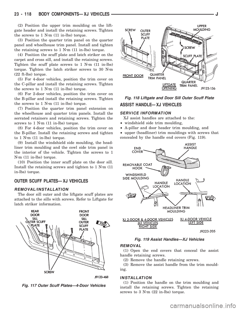
(2) Position the upper trim moulding on the lift-
gate header and install the retaining screws. Tighten
the screws to 1 Nzm (11 in-lbs) torque.
(3) Position the quarter trim panel on the quarter
panel and wheelhouse trim panel. Install and tighten
the retaining screws to 1 Nzm (11 in-lbs) torque.
(4) Position the scuff plate and latch striker on the
carpet and cross sill, and install the retaining screws.
Tighten the scuff plate screws to 1 Nzm (11 in-lbs)
torque. Tighten the latch striker screws to 30 Nzm
(22 ft-lbs) torque.
(5) For 4-door vehicles, position the trim cover on
the C-pillar and install the retaining screws. Tighten
the screws to 1 Nzm (11 in-lbs) torque.
(6) For 2-door vehicles, position the trim cover on
the B-pillar and install the retaining screws. Tighten
the screws to 1 Nzm (11 in-lbs) torque.
(7) Position the quarter trim panel extension on
the wheelhouse and quarter trim panels. Install the
serrated retainers and retaining screws. Tighten the
screws to 1 Nzm (11 in-lbs) torque.
(8) For 4-door vehicles, position the trim cover on
the B-pillar. Install the retaining screws and tighten
to1Nzm (11 in-lbs) torque.
(9) Install the windshield side moulding, the head-
liner trim moulding and the cowl side trim panel in
the interior of the vehicle. Tighten the screws to 1
Nzm (11 in-lbs) torque.
(10) Position the inner scuff plate on the door sill.
Install the retaining screws and tighten to 1 Nzm(11
in-lbs) torque.
OUTER SCUFF PLATESÐXJ VEHICLES
REMOVAL/INSTALLATION
The door sill outer and the liftgate scuff plates are
attached to the sills with screws. Refer to Liftgate for
latch striker information.
ASSIST HANDLEÐXJ VEHICLES
SERVICE INFORMATION
XJ assist handles are attached to the:
²windshield side trim moulding,
²A-pillar and door header trim moulding, and
²upper (headliner) trim mouldings with screws that
concealed by the handle end covers (Fig. 119).
REMOVAL
(1) Open the end covers that conceal the assist
handle retaining screws.
(2) Remove the handle retaining screws.
(3) Remove the assist handle from the trim mould-
ing.
INSTALLATION
(1) Position the handle on the trim moulding and
install the retaining screws. Tighten the retaining
screws to 3 Nzm (22 in-lbs) torque.Fig. 117 Outer Scuff PlatesÐ4-Door Vehicles
Fig. 118 Liftgate and Door Sill Outer Scuff Plate
Fig. 119 Assist HandlesÐXJ Vehicles
23 - 118 BODY COMPONENTSÐXJ VEHICLESJ
Page 1576 of 1784
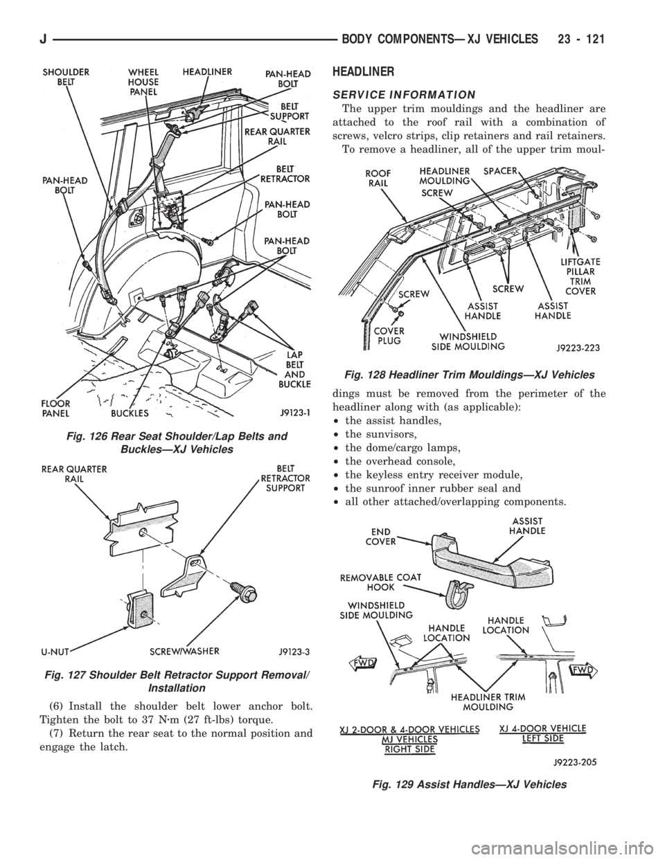
(6) Install the shoulder belt lower anchor bolt.
Tighten the bolt to 37 Nzm (27 ft-lbs) torque.
(7) Return the rear seat to the normal position and
engage the latch.
HEADLINER
SERVICE INFORMATION
The upper trim mouldings and the headliner are
attached to the roof rail with a combination of
screws, velcro strips, clip retainers and rail retainers.
To remove a headliner, all of the upper trim moul-
dings must be removed from the perimeter of the
headliner along with (as applicable):
²the assist handles,
²the sunvisors,
²the dome/cargo lamps,
²the overhead console,
²the keyless entry receiver module,
²the sunroof inner rubber seal and
²all other attached/overlapping components.
Fig. 128 Headliner Trim MouldingsÐXJ Vehicles
Fig. 129 Assist HandlesÐXJ Vehicles
Fig. 126 Rear Seat Shoulder/Lap Belts and
BucklesÐXJ Vehicles
Fig. 127 Shoulder Belt Retractor Support Removal/
Installation
JBODY COMPONENTSÐXJ VEHICLES 23 - 121
Page 1579 of 1784
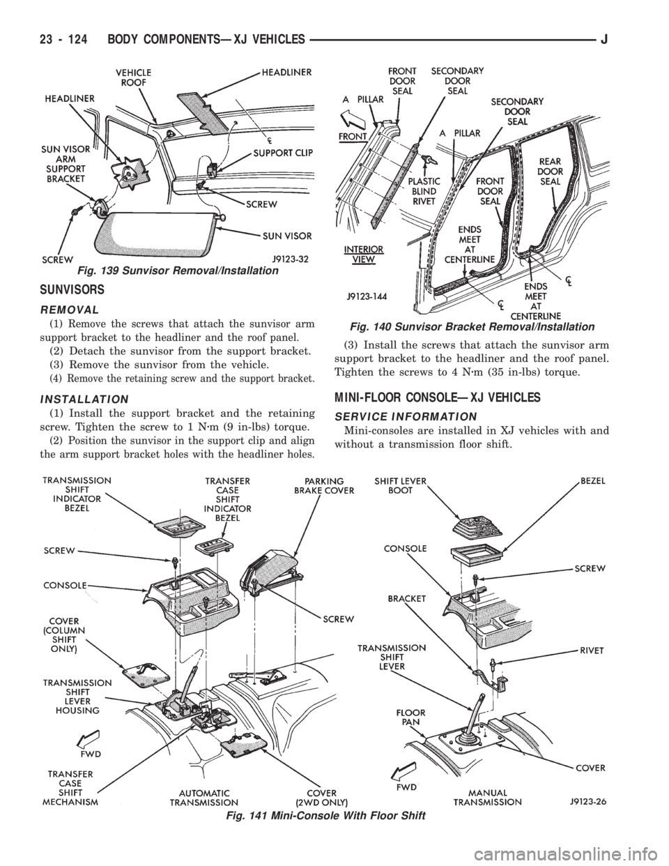
SUNVISORS
REMOVAL
(1) Remove the screws that attach the sunvisor arm
support bracket to the headliner and the roof panel.
(2) Detach the sunvisor from the support bracket.
(3) Remove the sunvisor from the vehicle.
(4) Remove the retaining screw and the support bracket.
INSTALLATION
(1) Install the support bracket and the retaining
screw. Tighten the screw to 1 Nzm (9 in-lbs) torque.
(2) Position the sunvisor in the support clip and align
the arm support bracket holes with the headliner holes.
(3) Install the screws that attach the sunvisor arm
support bracket to the headliner and the roof panel.
Tighten the screws to 4 Nzm (35 in-lbs) torque.
MINI-FLOOR CONSOLEÐXJ VEHICLES
SERVICE INFORMATION
Mini-consoles are installed in XJ vehicles with and
without a transmission floor shift.
Fig. 139 Sunvisor Removal/Installation
Fig. 140 Sunvisor Bracket Removal/Installation
Fig. 141 Mini-Console With Floor Shift
23 - 124 BODY COMPONENTSÐXJ VEHICLESJ