1994 JEEP CHEROKEE service
[x] Cancel search: servicePage 1582 of 1784
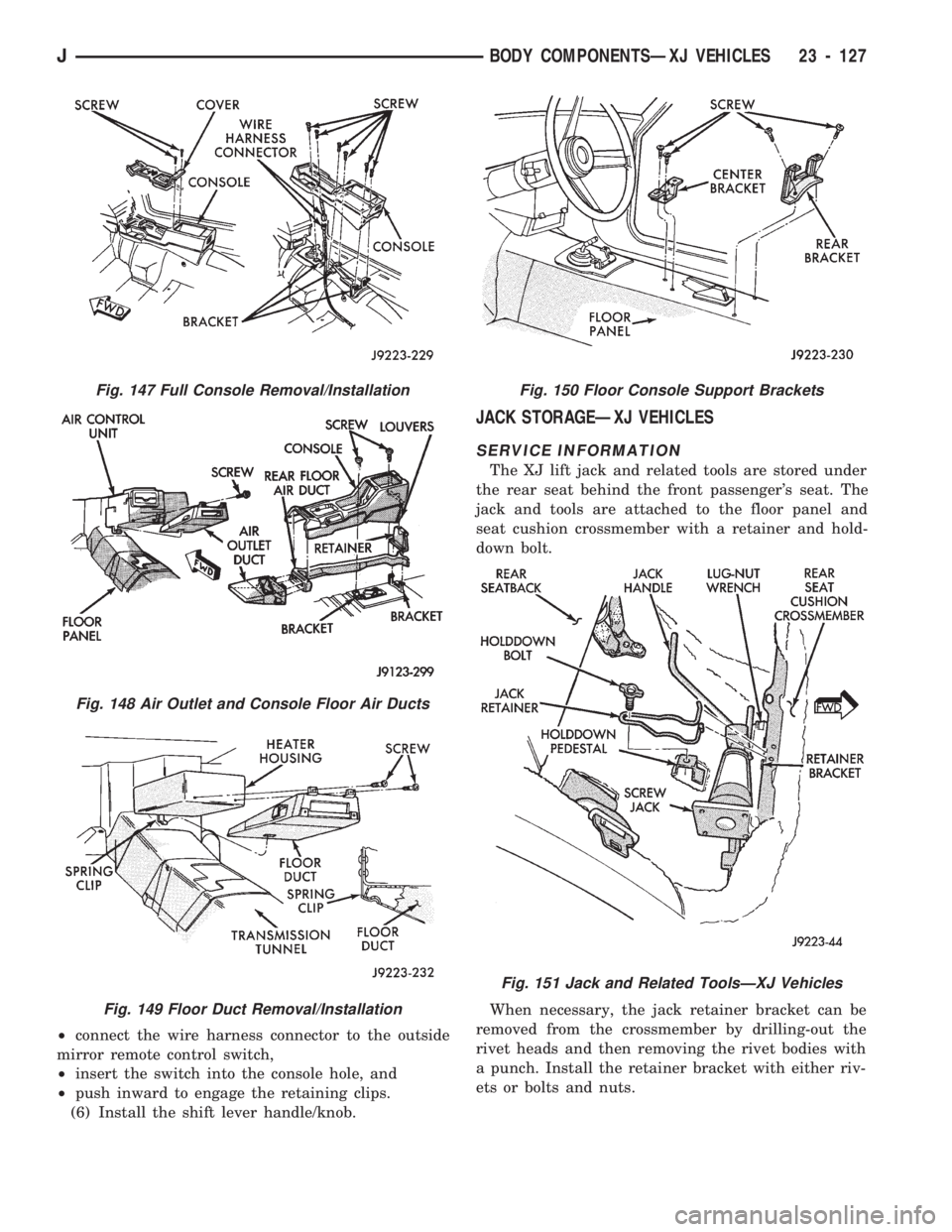
²connect the wire harness connector to the outside
mirror remote control switch,
²insert the switch into the console hole, and
²push inward to engage the retaining clips.
(6) Install the shift lever handle/knob.
JACK STORAGEÐXJ VEHICLES
SERVICE INFORMATION
The XJ lift jack and related tools are stored under
the rear seat behind the front passenger's seat. The
jack and tools are attached to the floor panel and
seat cushion crossmember with a retainer and hold-
down bolt.
When necessary, the jack retainer bracket can be
removed from the crossmember by drilling-out the
rivet heads and then removing the rivet bodies with
a punch. Install the retainer bracket with either riv-
ets or bolts and nuts.
Fig. 147 Full Console Removal/Installation
Fig. 148 Air Outlet and Console Floor Air Ducts
Fig. 149 Floor Duct Removal/Installation
Fig. 150 Floor Console Support Brackets
Fig. 151 Jack and Related ToolsÐXJ Vehicles
JBODY COMPONENTSÐXJ VEHICLES 23 - 127
Page 1584 of 1784
CARPETS AND FLOOR MATS
SERVICE INFORMATION
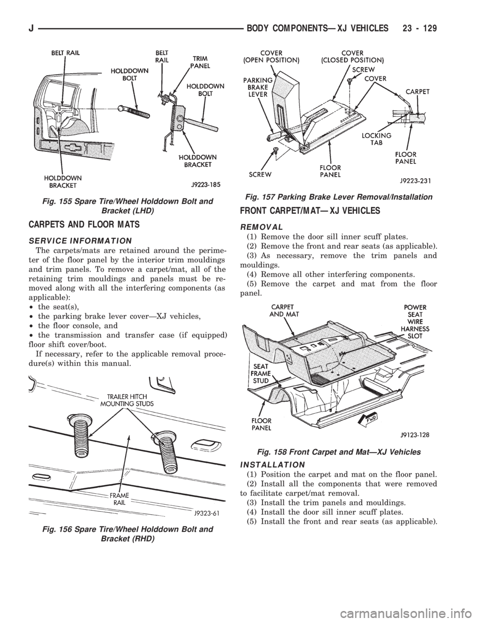
The carpets/mats are retained around the perime-
ter of the floor panel by the interior trim mouldings
and trim panels. To remove a carpet/mat, all of the
retaining trim mouldings and panels must be re-
moved along with all the interfering components (as
applicable):
²the seat(s),
²the parking brake lever coverÐXJ vehicles,
²the floor console, and
²the transmission and transfer case (if equipped)
floor shift cover/boot.
If necessary, refer to the applicable removal proce-
dure(s) within this manual.
FRONT CARPET/MATÐXJ VEHICLES
REMOVAL
(1) Remove the door sill inner scuff plates.
(2) Remove the front and rear seats (as applicable).
(3) As necessary, remove the trim panels and
mouldings.
(4) Remove all other interfering components.
(5) Remove the carpet and mat from the floor
panel.
INSTALLATION
(1) Position the carpet and mat on the floor panel.
(2) Install all the components that were removed
to facilitate carpet/mat removal.
(3) Install the trim panels and mouldings.
(4) Install the door sill inner scuff plates.
(5) Install the front and rear seats (as applicable).
Fig. 156 Spare Tire/Wheel Holddown Bolt and
Bracket (RHD)
Fig. 155 Spare Tire/Wheel Holddown Bolt and
Bracket (LHD)Fig. 157 Parking Brake Lever Removal/Installation
Fig. 158 Front Carpet and MatÐXJ Vehicles
JBODY COMPONENTSÐXJ VEHICLES 23 - 129
Page 1587 of 1784
BODY COMPONENTSÐYJ VEHICLES
CONTENTS
page page
ADD-A-TRUNK........................ 198
DOORS.............................. 172
EXTERIOR COMPONENTS............... 134FIXED WINDOW GLASS................ 181
GENERAL SERVICE INFORMATION........ 132
INTERIOR COMPONENTS............... 188
GENERAL SERVICE INFORMATION
LABELS/DECALS/PLATES
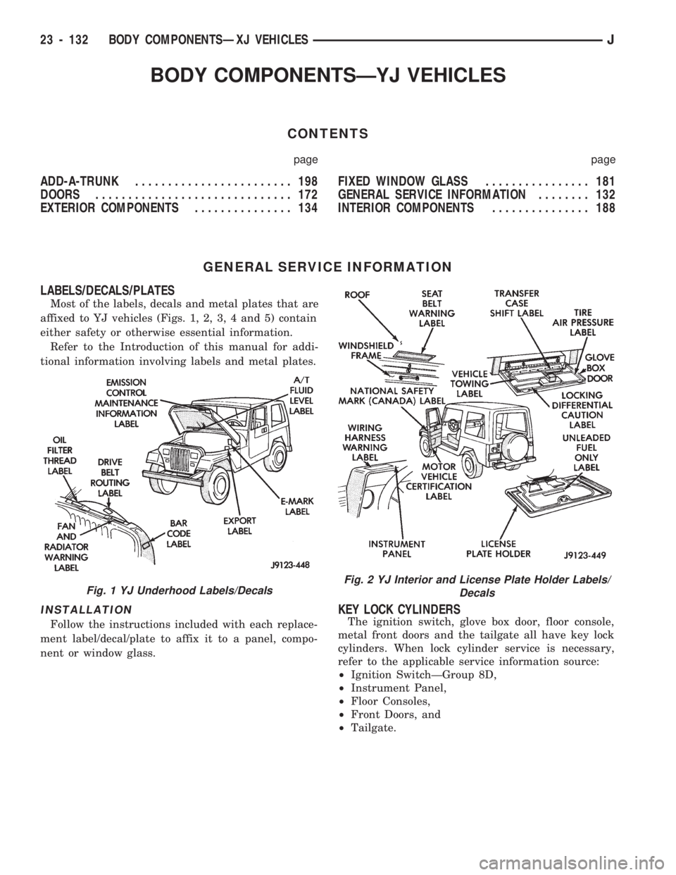
Most of the labels, decals and metal plates that are
affixed to YJ vehicles (Figs. 1, 2, 3, 4 and 5) contain
either safety or otherwise essential information.
Refer to the Introduction of this manual for addi-
tional information involving labels and metal plates.
INSTALLATION
Follow the instructions included with each replace-
ment label/decal/plate to affix it to a panel, compo-
nent or window glass.
KEY LOCK CYLINDERS
The ignition switch, glove box door, floor console,
metal front doors and the tailgate all have key lock
cylinders. When lock cylinder service is necessary,
refer to the applicable service information source:
²Ignition SwitchÐGroup 8D,
²Instrument Panel,
²Floor Consoles,
²Front Doors, and
²Tailgate.
Fig. 1 YJ Underhood Labels/DecalsFig. 2 YJ Interior and License Plate Holder Labels/
Decals
23 - 132 BODY COMPONENTSÐXJ VEHICLESJ
Page 1589 of 1784
EXTERIOR COMPONENTS
INDEX
page page
Battery Tray........................... 140
Body Extension Panels and FasciasÐYJ
Renegade Vehicles..................... 147
Body Side Step Moulding................. 145
Body Stripes/Decals..................... 153
Cowl Grille and Screen................... 139
Cowl Weatherstrip Seal................... 139
Exterior Nameplates (Adhesive-Backed)....... 158
External Spare/Wheel Tire Carrier........... 172
Fender Flare........................... 144
Fender Inner Splash Shields............... 147
Fender Splash Aprons.................... 147
Fenders............................... 141
Fog LampÐYJ Renegade Vehicles.......... 150
Front Fascia and Skid PlateÐYJ Renegade
Vehicles............................. 148
Front Fender Extension PanelÐYJ Renegade
Vehicles............................. 149
Fuel Filler Protector/Nozzle................ 158
Half Metal Door Mirror (External)............ 158
Hard Top Liftgate Glass.................. 162
Hard Top Repair........................ 165
Hard Top Roof Vent..................... 165
Hard Top Service....................... 164
Hard Top Service Information.............. 164Hood................................. 137
Hood Alignment......................... 138
Hood Insulator Panel..................... 138
Hood Safety Latch....................... 139
Liftgate Glass Weatherstrip Seal Replacement . . 163
Radiator Grille Applique................... 134
Rear Fascia and Skid PlateÐYJ Renegade
Vehicles............................. 152
Rear Quarter Extension PanelÐYJ Renegade
Vehicles............................. 151
Rocker Extension PanelÐYJ Renegade
Vehicles............................. 150
Soft Top Service........................ 167
Soft Top Service Information............... 166
Sport Bar............................. 171
Tailgate Adjustment...................... 160
Tailgate Hinge.......................... 159
Tailgate Latch and Release Handle.......... 160
Tailgate Latch Striker..................... 161
Tailgate Lock Cylinder.................... 160
Tailgate Service......................... 159
Tailgate Service Information................ 159
Tailgate Weatherstrip Seal................. 161
Wheelhouse Splash Liners................ 146
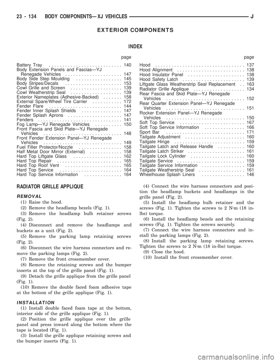
RADIATOR GRILLE APPLIQUE
REMOVAL
(1) Raise the hood.
(2) Remove the headlamp bezels (Fig. 1).
(3) Remove the headlamp bulb retainer screws
(Fig. 2).
(4) Disconnect and remove the headlamps and
buckets as a unit (Fig. 2).
(5) Remove the parking lamp retaining screws
(Fig. 2).
(6) Disconnect the wire harness connectors and re-
move the parking lamps (Fig. 2).
(7) Remove the front crossmember cover.
(8) Remove the retaining screws and the bumper
inserts at the top of the grille panel (Fig. 1).
(9) Detach the grille applique from the grille panel
(Fig. 1).
(10) Remove the double faced foam adhesive tape
at the bottom of the grille applique (Fig. 1).
INSTALLATION
(1) Install double faced foam tape at the bottom,
interior side of the grille applique (Fig. 1).
(2) Position the grille applique over the grille
panel and press inward along the bottom where the
tape is located (Fig. 1).
(3) Install the grille applique retaining screws and
the bumper inserts (Fig. 1).(4) Connect the wire harness connectors and posi-
tion the headlamp buckets and headlamps in the
grille panel (Fig. 2).
(5) Install the headlamp bulb retainer and the
screws (Fig. 1). Tighten the screws to 2 Nzm (18 in-
lbs) torque.
(6) Install the headlamp bezels and the retaining
screws (Fig. 1). Tighten the screws securely.
(7) Connect the wire harness connectors and in-
stall the parking lamps (Fig. 2).
(8) Install the parking lamp retaining screws.
Tighten the screws to 2 Nzm (18 in-lbs) torque.
(9) Close the hood.
(10) Install the front crossmember cover.
23 - 134 BODY COMPONENTSÐXJ VEHICLESJ
Page 1596 of 1784
FENDERS
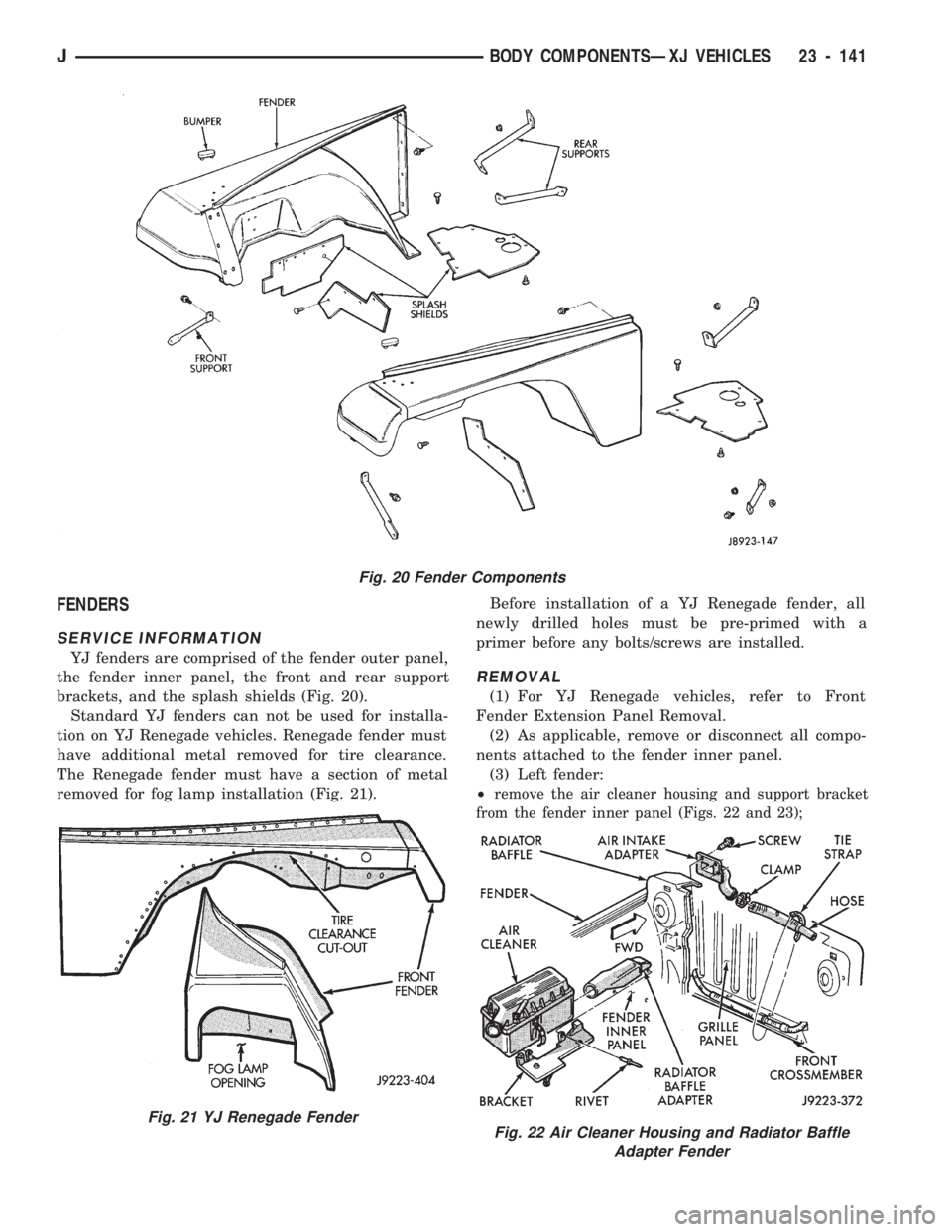
SERVICE INFORMATION
YJ fenders are comprised of the fender outer panel,
the fender inner panel, the front and rear support
brackets, and the splash shields (Fig. 20).
Standard YJ fenders can not be used for installa-
tion on YJ Renegade vehicles. Renegade fender must
have additional metal removed for tire clearance.
The Renegade fender must have a section of metal
removed for fog lamp installation (Fig. 21).Before installation of a YJ Renegade fender, all
newly drilled holes must be pre-primed with a
primer before any bolts/screws are installed.
REMOVAL
(1) For YJ Renegade vehicles, refer to Front
Fender Extension Panel Removal.
(2) As applicable, remove or disconnect all compo-
nents attached to the fender inner panel.
(3) Left fender:
²
remove the air cleaner housing and support bracket
from the fender inner panel (Figs. 22 and 23);
Fig. 20 Fender Components
Fig. 21 YJ Renegade FenderFig. 22 Air Cleaner Housing and Radiator Baffle
Adapter Fender
JBODY COMPONENTSÐXJ VEHICLES 23 - 141
Page 1602 of 1784
FENDER SPLASH APRONS
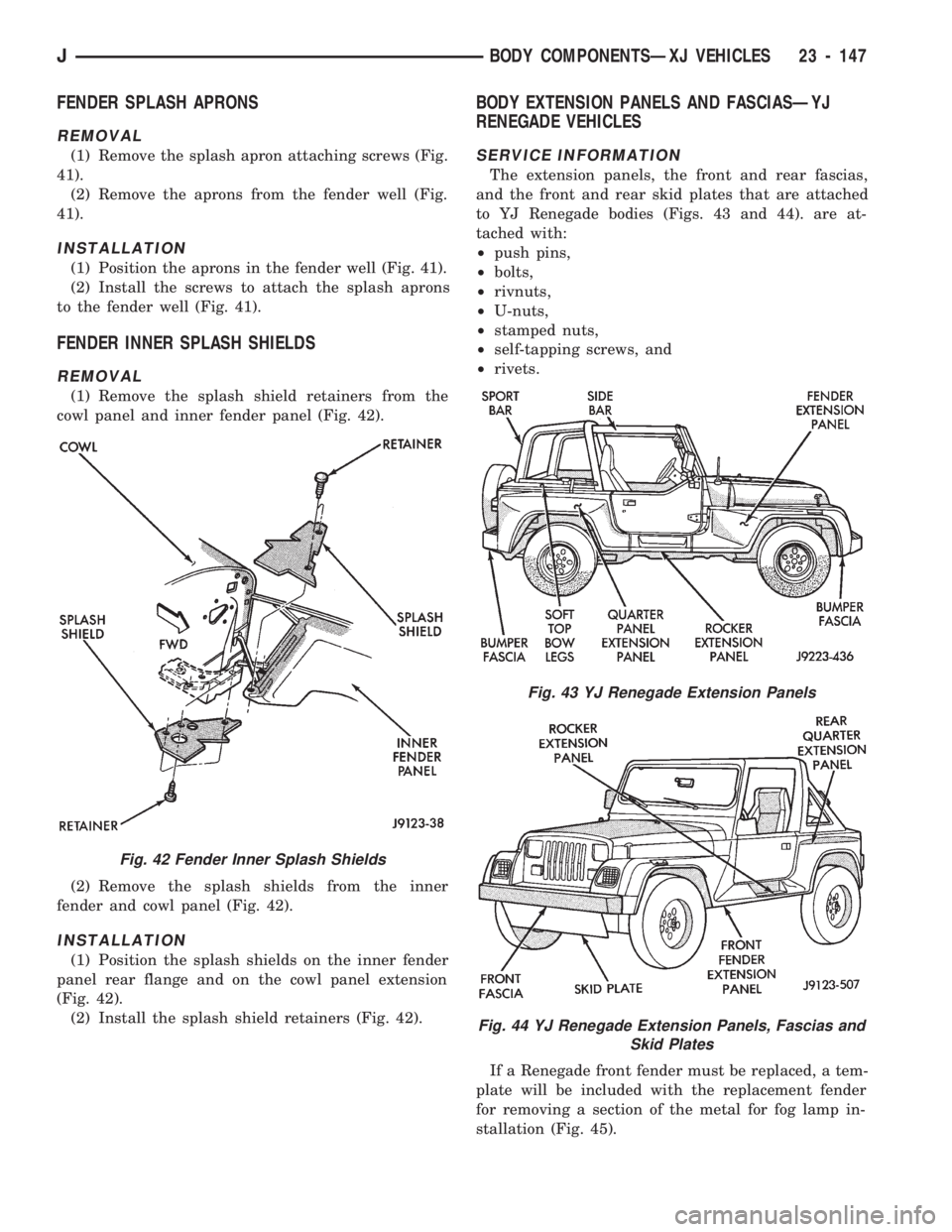
REMOVAL
(1) Remove the splash apron attaching screws (Fig.
41).
(2) Remove the aprons from the fender well (Fig.
41).
INSTALLATION
(1) Position the aprons in the fender well (Fig. 41).
(2) Install the screws to attach the splash aprons
to the fender well (Fig. 41).
FENDER INNER SPLASH SHIELDS
REMOVAL
(1) Remove the splash shield retainers from the
cowl panel and inner fender panel (Fig. 42).
(2) Remove the splash shields from the inner
fender and cowl panel (Fig. 42).
INSTALLATION
(1) Position the splash shields on the inner fender
panel rear flange and on the cowl panel extension
(Fig. 42).
(2) Install the splash shield retainers (Fig. 42).
BODY EXTENSION PANELS AND FASCIASÐYJ
RENEGADE VEHICLES
SERVICE INFORMATION
The extension panels, the front and rear fascias,
and the front and rear skid plates that are attached
to YJ Renegade bodies (Figs. 43 and 44). are at-
tached with:
²push pins,
²bolts,
²rivnuts,
²U-nuts,
²stamped nuts,
²self-tapping screws, and
²rivets.
If a Renegade front fender must be replaced, a tem-
plate will be included with the replacement fender
for removing a section of the metal for fog lamp in-
stallation (Fig. 45).
Fig. 42 Fender Inner Splash Shields
Fig. 43 YJ Renegade Extension Panels
Fig. 44 YJ Renegade Extension Panels, Fascias and
Skid Plates
JBODY COMPONENTSÐXJ VEHICLES 23 - 147
Page 1608 of 1784
(3) Remove the retaining bolts from the skid plate
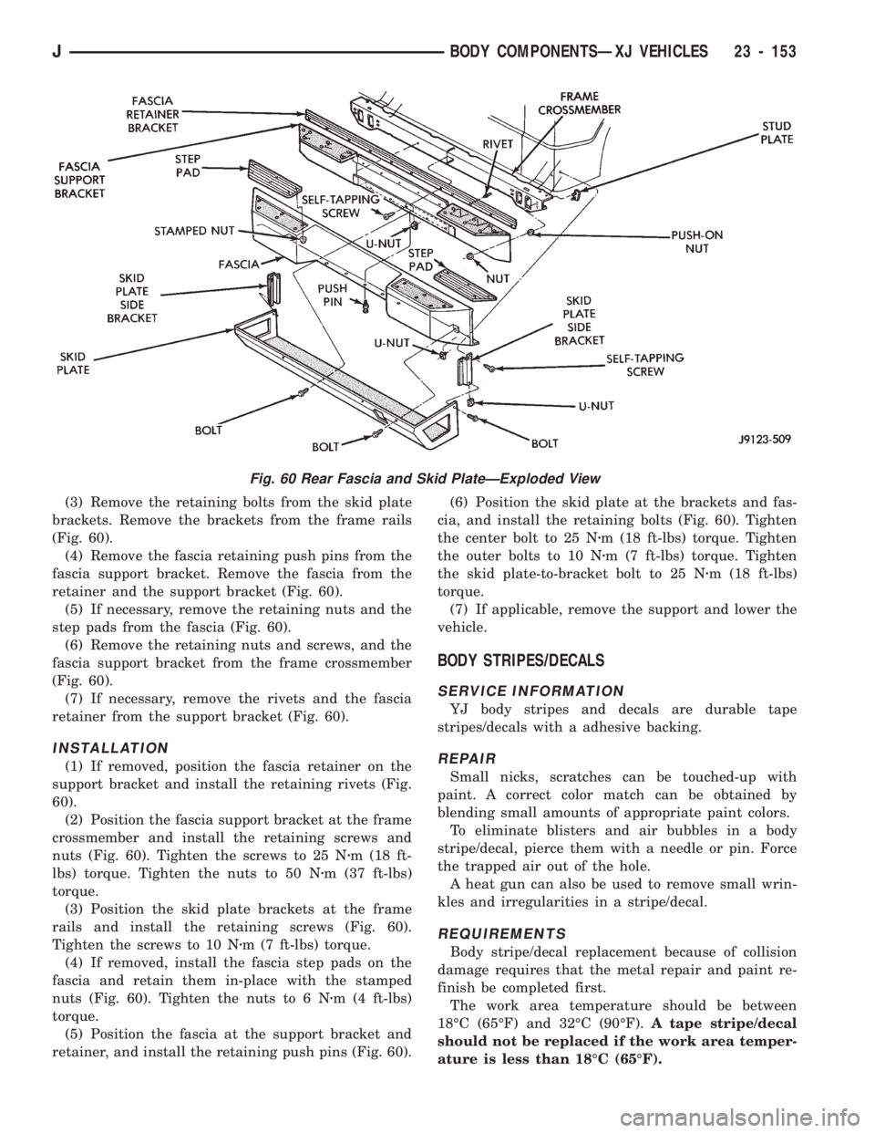
brackets. Remove the brackets from the frame rails
(Fig. 60).
(4) Remove the fascia retaining push pins from the
fascia support bracket. Remove the fascia from the
retainer and the support bracket (Fig. 60).
(5) If necessary, remove the retaining nuts and the
step pads from the fascia (Fig. 60).
(6) Remove the retaining nuts and screws, and the
fascia support bracket from the frame crossmember
(Fig. 60).
(7) If necessary, remove the rivets and the fascia
retainer from the support bracket (Fig. 60).
INSTALLATION
(1) If removed, position the fascia retainer on the
support bracket and install the retaining rivets (Fig.
60).
(2) Position the fascia support bracket at the frame
crossmember and install the retaining screws and
nuts (Fig. 60). Tighten the screws to 25 Nzm (18 ft-
lbs) torque. Tighten the nuts to 50 Nzm (37 ft-lbs)
torque.
(3) Position the skid plate brackets at the frame
rails and install the retaining screws (Fig. 60).
Tighten the screws to 10 Nzm (7 ft-lbs) torque.
(4) If removed, install the fascia step pads on the
fascia and retain them in-place with the stamped
nuts (Fig. 60). Tighten the nuts to 6 Nzm (4 ft-lbs)
torque.
(5) Position the fascia at the support bracket and
retainer, and install the retaining push pins (Fig. 60).(6) Position the skid plate at the brackets and fas-
cia, and install the retaining bolts (Fig. 60). Tighten
the center bolt to 25 Nzm (18 ft-lbs) torque. Tighten
the outer bolts to 10 Nzm (7 ft-lbs) torque. Tighten
the skid plate-to-bracket bolt to 25 Nzm (18 ft-lbs)
torque.
(7) If applicable, remove the support and lower the
vehicle.
BODY STRIPES/DECALS
SERVICE INFORMATION
YJ body stripes and decals are durable tape
stripes/decals with a adhesive backing.
REPAIR
Small nicks, scratches can be touched-up with
paint. A correct color match can be obtained by
blending small amounts of appropriate paint colors.
To eliminate blisters and air bubbles in a body
stripe/decal, pierce them with a needle or pin. Force
the trapped air out of the hole.
A heat gun can also be used to remove small wrin-
kles and irregularities in a stripe/decal.
REQUIREMENTS
Body stripe/decal replacement because of collision
damage requires that the metal repair and paint re-
finish be completed first.
The work area temperature should be between
18ÉC (65ÉF) and 32ÉC (90ÉF).A tape stripe/decal
should not be replaced if the work area temper-
ature is less than 18ÉC (65ÉF).
Fig. 60 Rear Fascia and Skid PlateÐExploded View
JBODY COMPONENTSÐXJ VEHICLES 23 - 153
Page 1614 of 1784
(2) Remove the mirror from the door hinge (Fig.
78).
INSTALLATION
(1) Clean the door hinge-mirror base contact sur-
face.
(2) Position the mirror base at the door hinge (Fig.
78).
(3) Install the mirror base attaching screws in the
door hinge (Fig. 78). Tighten the attaching screws to
11 Nzm (96 in-lbs) torque.
TAILGATE SERVICE INFORMATION
The following tailgate service procedures include:
²tailgate removal/installation,
²tailgate hinge replacement,
²tailgate adjustment,
²tailgate latch removal/installation,
²tailgate lock cylinder removal/installation,
²tailgate latch striker removal/installation, and
²tailgate seal replacement.
TAILGATE SERVICE
REMOVAL
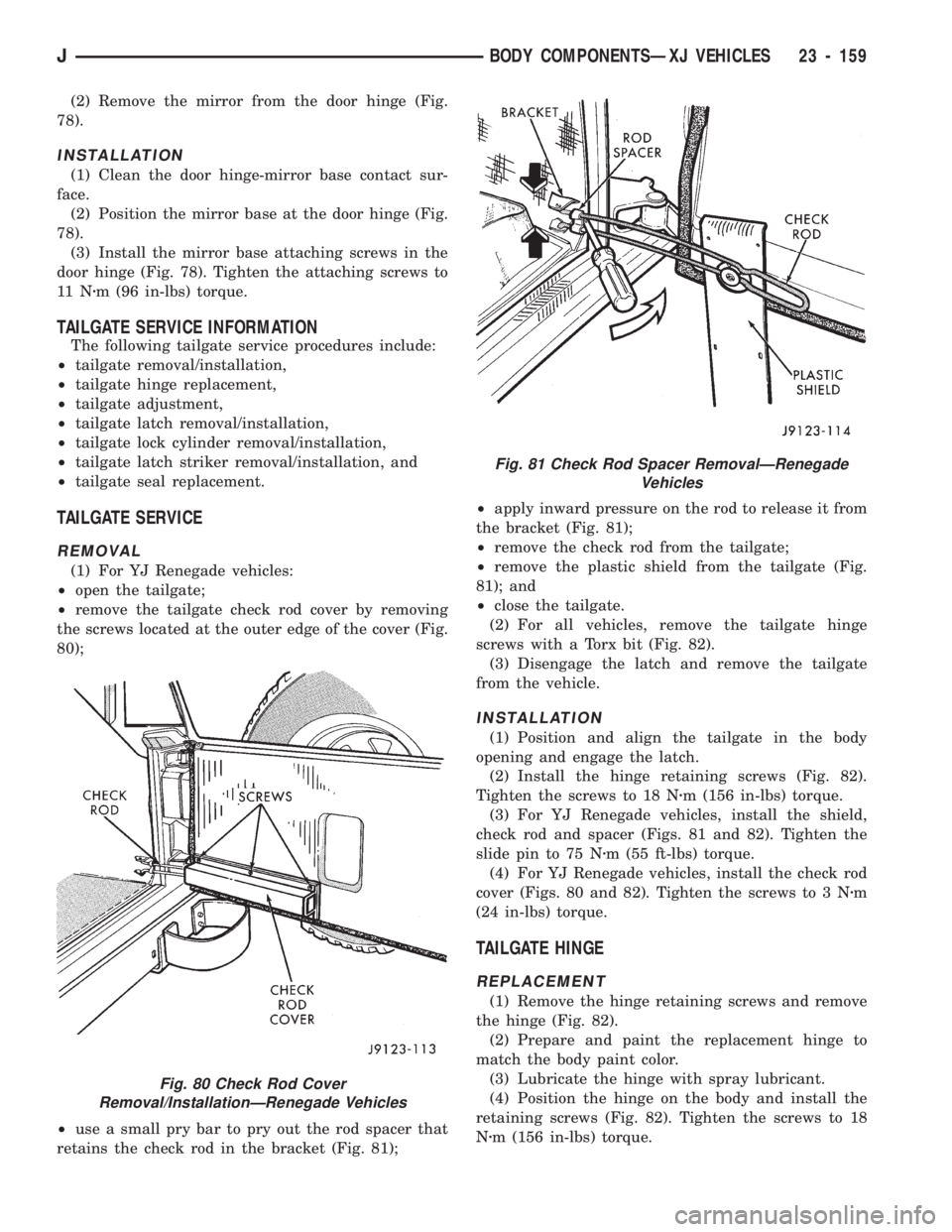
(1) For YJ Renegade vehicles:
²open the tailgate;
²remove the tailgate check rod cover by removing
the screws located at the outer edge of the cover (Fig.
80);
²use a small pry bar to pry out the rod spacer that
retains the check rod in the bracket (Fig. 81);²apply inward pressure on the rod to release it from
the bracket (Fig. 81);
²remove the check rod from the tailgate;
²remove the plastic shield from the tailgate (Fig.
81); and
²close the tailgate.
(2) For all vehicles, remove the tailgate hinge
screws with a Torx bit (Fig. 82).
(3) Disengage the latch and remove the tailgate
from the vehicle.
INSTALLATION
(1) Position and align the tailgate in the body
opening and engage the latch.
(2) Install the hinge retaining screws (Fig. 82).
Tighten the screws to 18 Nzm (156 in-lbs) torque.
(3) For YJ Renegade vehicles, install the shield,
check rod and spacer (Figs. 81 and 82). Tighten the
slide pin to 75 Nzm (55 ft-lbs) torque.
(4) For YJ Renegade vehicles, install the check rod
cover (Figs. 80 and 82). Tighten the screws to 3 Nzm
(24 in-lbs) torque.
TAILGATE HINGE
REPLACEMENT
(1) Remove the hinge retaining screws and remove
the hinge (Fig. 82).
(2) Prepare and paint the replacement hinge to
match the body paint color.
(3) Lubricate the hinge with spray lubricant.
(4) Position the hinge on the body and install the
retaining screws (Fig. 82). Tighten the screws to 18
Nzm (156 in-lbs) torque.
Fig. 80 Check Rod Cover
Removal/InstallationÐRenegade Vehicles
Fig. 81 Check Rod Spacer RemovalÐRenegade
Vehicles
JBODY COMPONENTSÐXJ VEHICLES 23 - 159