1994 JEEP CHEROKEE service
[x] Cancel search: servicePage 1618 of 1784
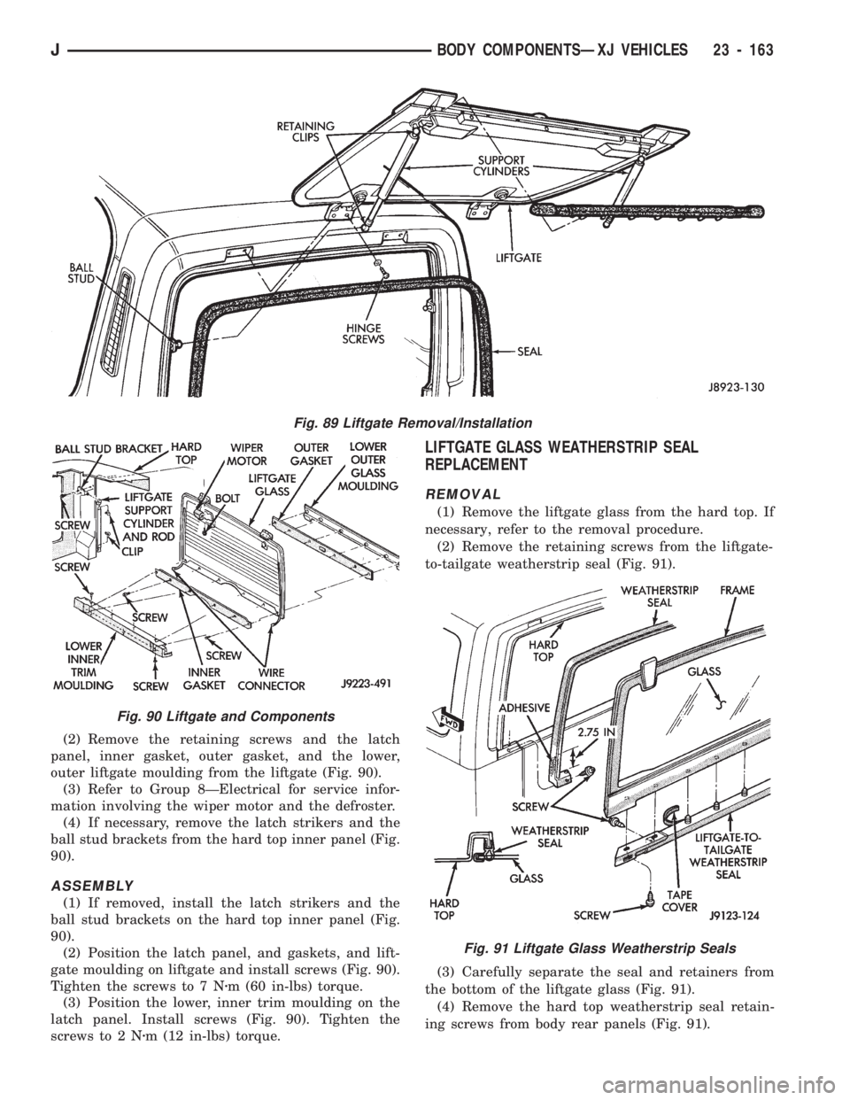
(2) Remove the retaining screws and the latch
panel, inner gasket, outer gasket, and the lower,
outer liftgate moulding from the liftgate (Fig. 90).
(3) Refer to Group 8ÐElectrical for service infor-
mation involving the wiper motor and the defroster.
(4) If necessary, remove the latch strikers and the
ball stud brackets from the hard top inner panel (Fig.
90).
ASSEMBLY
(1) If removed, install the latch strikers and the
ball stud brackets on the hard top inner panel (Fig.
90).
(2) Position the latch panel, and gaskets, and lift-
gate moulding on liftgate and install screws (Fig. 90).
Tighten the screws to 7 Nzm (60 in-lbs) torque.
(3) Position the lower, inner trim moulding on the
latch panel. Install screws (Fig. 90). Tighten the
screws to 2 Nzm (12 in-lbs) torque.
LIFTGATE GLASS WEATHERSTRIP SEAL
REPLACEMENT
REMOVAL
(1) Remove the liftgate glass from the hard top. If
necessary, refer to the removal procedure.
(2) Remove the retaining screws from the liftgate-
to-tailgate weatherstrip seal (Fig. 91).
(3) Carefully separate the seal and retainers from
the bottom of the liftgate glass (Fig. 91).
(4) Remove the hard top weatherstrip seal retain-
ing screws from body rear panels (Fig. 91).
Fig. 91 Liftgate Glass Weatherstrip Seals
Fig. 89 Liftgate Removal/Installation
Fig. 90 Liftgate and Components
JBODY COMPONENTSÐXJ VEHICLES 23 - 163
Page 1619 of 1784
(5) Carefully separate the weatherstrip seal from
the rear panels and the hard top (Fig. 91).
(6) Remove the residual adhesive from the seal
contact areas.
INSTALLATION
(1) Remove the tape cover and position the lift-
gate-to-tailgate weatherstrip seal at the bottom of
the liftgate glass (Fig. 91).
(2) Carefully insert the retainers into the holes
and press the seal against the bottom of the liftgate
glass (Fig. 91).
(3) Install the liftgate-to-tailgate weatherstrip seal
screws (Fig. 91). Tighten the screws securely.
(4) Apply weatherstrip adhesive to the hard top
weatherstrip seal as indicated in Figure 91.
(5) Carefully position the weatherstrip seal on the
rear panels and the hard top (Fig. 91).
(6) Press the seal onto the hard top flange and en-
sure that it is correctly seated on the flange (Fig. 91).
(7) Install the seal retaining screws in the rear
panels and tighten them securely (Fig. 91).
HARD TOP SERVICE INFORMATION
The following service procedures include:
²hard top removal/installation, and
²hard top repair procedures.
The hard top is constructed of compressed molded
fiberglass and painted to a special spatter paint. The
hard top can be removed for service access or for
other purposes.
HARD TOP SERVICE
REMOVAL
CAUTION: When removing the hard top, avoid dam-
aging the foam sealant between the hard top and
body panels.
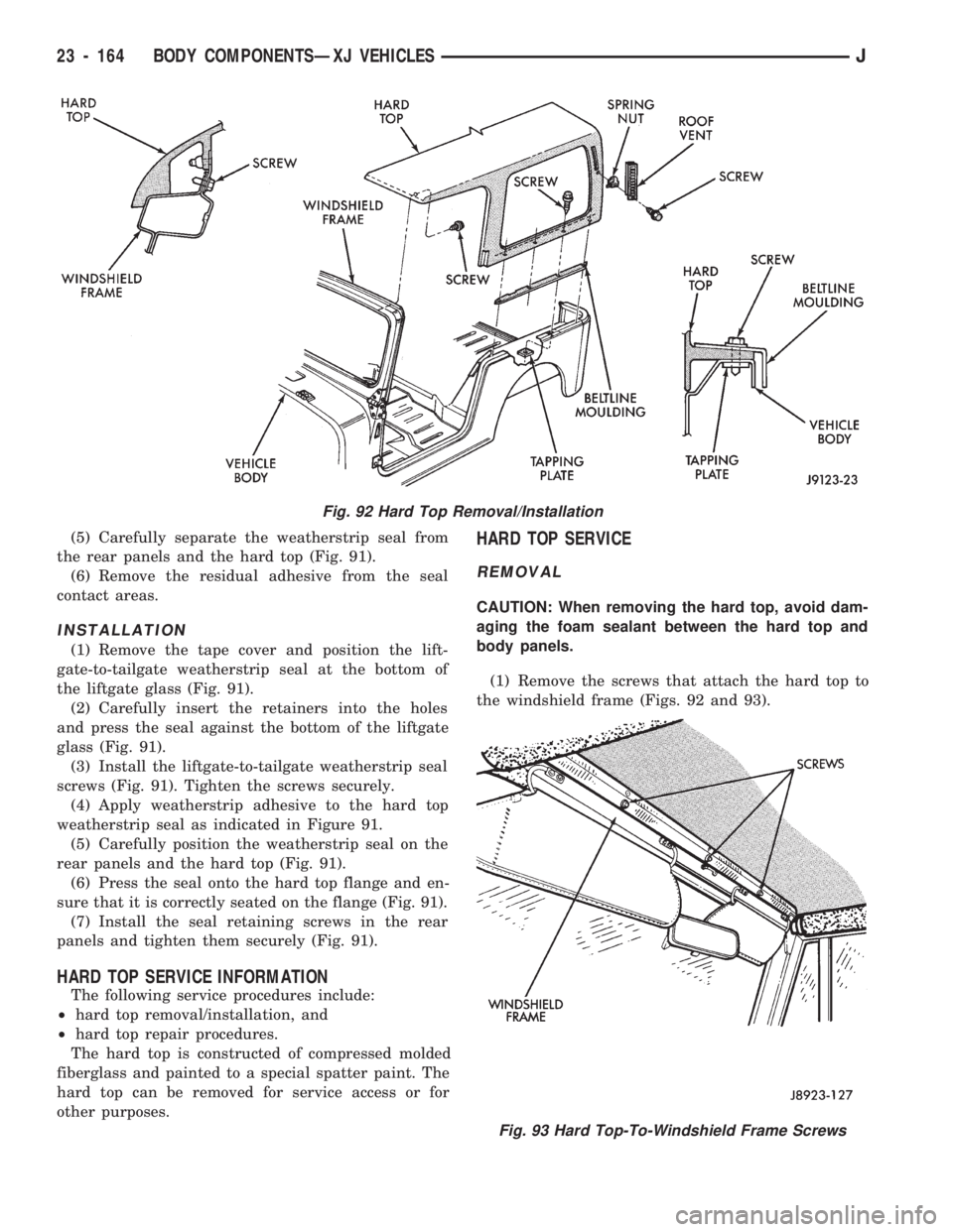
(1) Remove the screws that attach the hard top to
the windshield frame (Figs. 92 and 93).
Fig. 92 Hard Top Removal/Installation
Fig. 93 Hard Top-To-Windshield Frame Screws
23 - 164 BODY COMPONENTSÐXJ VEHICLESJ
Page 1621 of 1784
cloth. Use a plastic spreader to smooth-out the cloth
and resin. Use firm pressure to remove air bubbles
and to smooth-out the cloth.
(11) Allow the resin to ``cure''.
(12) Smooth-out the surface area to the contour of
the hard top with a 50-grit disc.
(13) Apply plastic filler to complete the repair.
Finish smoothing the surface area with 80-grit pa-
per.
(14) Repeat the previous step on the inside surface
area of the hard top.
(15) ``Featheredge'' the repaired surface area.
(16) Prime the repaired surface area with Ditzler
Epoxy Chromate Primer (DP-40/401), or an equiva-
lent product.
(17) Apply surface primer to the surface area.
(18) Sand the surface area for paint preparation.
After sanding, re-prime the surface area, if neces-
sary.
(19) Prime the surface area for the color coat.
(20) Color coat the repaired surface area.
FRACTURE REPAIR
(1) Use a grinder to remove the paint (from both,
the inner and outer surface areas of the hard top)
and to outline the damaged area.
(2) ``Stop-drill'' the crack(s) with a 3-mm (1/8-in)
diameter drill bit.(3) Bevel the edges of the crack(s) on both sides
with a rotary file.
The edges should be beveled on the inside and
outside of the top to ensure sufficient surface
area for good bonding.
(4) Complete the repairs with fiberglass cloth and
resin as described above in the hard top hole repair
procedure.
TEXTURED PAINT REPAIR
The textured paint applied to hard tops is available
from Mopar Parts sources. The paint supplied will
duplicate the original texture on the hard top.
SOFT TOP SERVICE INFORMATION
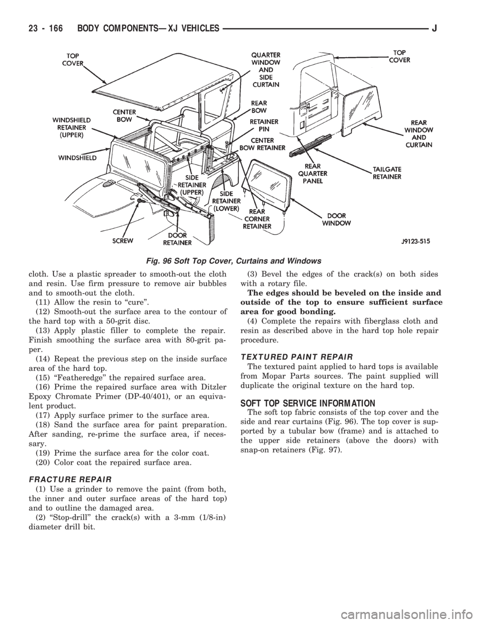
The soft top fabric consists of the top cover and the
side and rear curtains (Fig. 96). The top cover is sup-
ported by a tubular bow (frame) and is attached to
the upper side retainers (above the doors) with
snap-on retainers (Fig. 97).
Fig. 96 Soft Top Cover, Curtains and Windows
23 - 166 BODY COMPONENTSÐXJ VEHICLESJ
Page 1622 of 1784
SOFT TOP SERVICE
REMOVAL
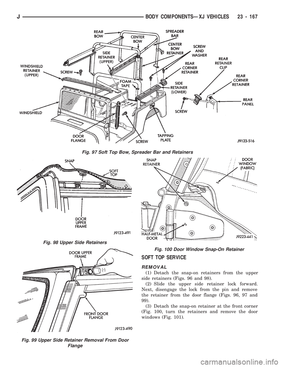
(1) Detach the snap-on retainers from the upper
side retainers (Figs. 96 and 98).
(2) Slide the upper side retainer lock forward.
Next, disengage the lock from the pin and remove
the retainer from the door flange (Figs. 96, 97 and
99).
(3) Detach the snap-on retainer at the front corner
(Fig. 100, turn the retainers and remove the door
windows (Fig. 101).
Fig. 97 Soft Top Bow, Spreader Bar and Retainers
Fig. 98 Upper Side Retainers
Fig. 99 Upper Side Retainer Removal From Door
Flange
Fig. 100 Door Window Snap-On Retainer
JBODY COMPONENTSÐXJ VEHICLES 23 - 167
Page 1628 of 1784
DOORS
INDEX
page page
Full-Metal Door Assist Handle.............. 175
Full-Metal Door Hinges................... 179
Full-Metal Door Key Lock Cylinder........... 178
Full-Metal Door Latch.................... 179
Full-Metal Door Latch External Release Handle . 178
Full-Metal Door Latch Inside Release and
Lock Handle.......................... 175
Full-Metal Door Service................... 181
Full-Metal Door Trim Panel................ 175Full-Metal Door Vent Window Glass......... 177
Full-Metal Door Waterdam................. 176
Full-Metal Door Weatherstrip Seals.......... 180
Full-Metal Door Window Glass.............. 178
Full-Metal Door Window Glass Regulator...... 177
Full-Metal Door Window Glass Regulator Handle. 175
Half-Metal Door Latch Striker............... 175
Half-Metal Soft Top Door.................. 173
HALF-METAL SOFT TOP DOOR
REMOVAL/DISASSEMBLY
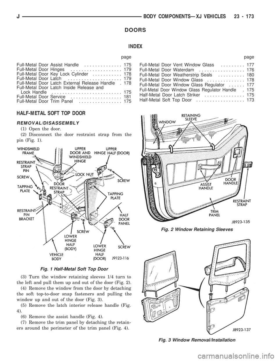
(1) Open the door.
(2) Disconnect the door restraint strap from the
pin (Fig. 1).
(3) Turn the window retaining sleeves 1/4 turn to
the left and pull them up and out of the door (Fig. 2).
(4) Remove the window from the door by detaching
the soft top-to-door snap fasteners and pulling the
window up and out of the door (Fig. 3).
(5) Remove the latch interior release handle (Fig.
4).
(6) Remove the assist handle (Fig. 4).
(7) Remove the trim panel by detaching the retain-
ers around the perimeter of the trim panel (Fig. 4).
Fig. 2 Window Retaining Sleeves
Fig. 3 Window Removal/Installation
Fig. 1 Half-Metal Soft Top Door
JBODY COMPONENTSÐXJ VEHICLES 23 - 173
Page 1635 of 1784
REPLACEMENT
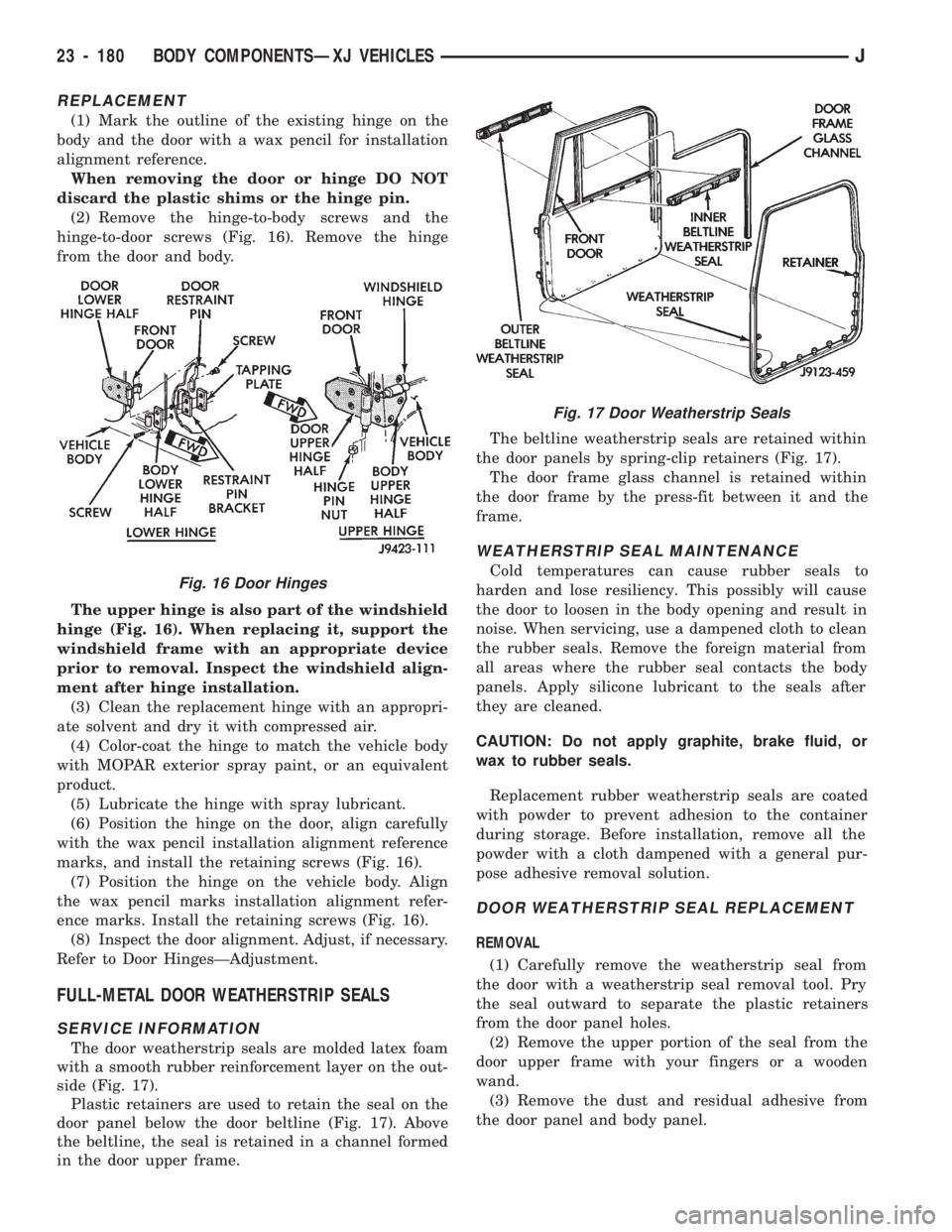
(1) Mark the outline of the existing hinge on the
body and the door with a wax pencil for installation
alignment reference.
When removing the door or hinge DO NOT
discard the plastic shims or the hinge pin.
(2) Remove the hinge-to-body screws and the
hinge-to-door screws (Fig. 16). Remove the hinge
from the door and body.
The upper hinge is also part of the windshield
hinge (Fig. 16). When replacing it, support the
windshield frame with an appropriate device
prior to removal. Inspect the windshield align-
ment after hinge installation.
(3) Clean the replacement hinge with an appropri-
ate solvent and dry it with compressed air.
(4) Color-coat the hinge to match the vehicle body
with MOPAR exterior spray paint, or an equivalent
product.
(5) Lubricate the hinge with spray lubricant.
(6) Position the hinge on the door, align carefully
with the wax pencil installation alignment reference
marks, and install the retaining screws (Fig. 16).
(7) Position the hinge on the vehicle body. Align
the wax pencil marks installation alignment refer-
ence marks. Install the retaining screws (Fig. 16).
(8) Inspect the door alignment. Adjust, if necessary.
Refer to Door HingesÐAdjustment.
FULL-METAL DOOR WEATHERSTRIP SEALS
SERVICE INFORMATION
The door weatherstrip seals are molded latex foam
with a smooth rubber reinforcement layer on the out-
side (Fig. 17).
Plastic retainers are used to retain the seal on the
door panel below the door beltline (Fig. 17). Above
the beltline, the seal is retained in a channel formed
in the door upper frame.The beltline weatherstrip seals are retained within
the door panels by spring-clip retainers (Fig. 17).
The door frame glass channel is retained within
the door frame by the press-fit between it and the
frame.
WEATHERSTRIP SEAL MAINTENANCE
Cold temperatures can cause rubber seals to
harden and lose resiliency. This possibly will cause
the door to loosen in the body opening and result in
noise. When servicing, use a dampened cloth to clean
the rubber seals. Remove the foreign material from
all areas where the rubber seal contacts the body
panels. Apply silicone lubricant to the seals after
they are cleaned.
CAUTION: Do not apply graphite, brake fluid, or
wax to rubber seals.
Replacement rubber weatherstrip seals are coated
with powder to prevent adhesion to the container
during storage. Before installation, remove all the
powder with a cloth dampened with a general pur-
pose adhesive removal solution.
DOOR WEATHERSTRIP SEAL REPLACEMENT
REMOVAL
(1) Carefully remove the weatherstrip seal from
the door with a weatherstrip seal removal tool. Pry
the seal outward to separate the plastic retainers
from the door panel holes.
(2) Remove the upper portion of the seal from the
door upper frame with your fingers or a wooden
wand.
(3) Remove the dust and residual adhesive from
the door panel and body panel.
Fig. 17 Door Weatherstrip Seals
Fig. 16 Door Hinges
23 - 180 BODY COMPONENTSÐXJ VEHICLESJ
Page 1636 of 1784
INSTALLATION
(1) Apply adhesive to the front, rear and bottom
edges of the door from the beltline downward.
(2) Install the upper front corner of the seal on the
door first using your fingers or a wooden wand to po-
sition the seal in the channel. Place the inner shoul-
der of the seal in the channel-to-window frame above
the beltline.
(3) Force the retainers, starting at the rear edge of
the door, into the door panel holes.
(4) Ensure that the seal is completely seated
around the door.
BELTLINE SEAL REPLACEMENT
REMOVAL
(1) Carefully remove the beltline weatherstrip seal
(Fig. 17) from the door with a weatherstrip seal re-
moval tool or similar pry tool.
(2) Pry the seal upward to remove it from within
the glass and door panel.
INSTALLATION
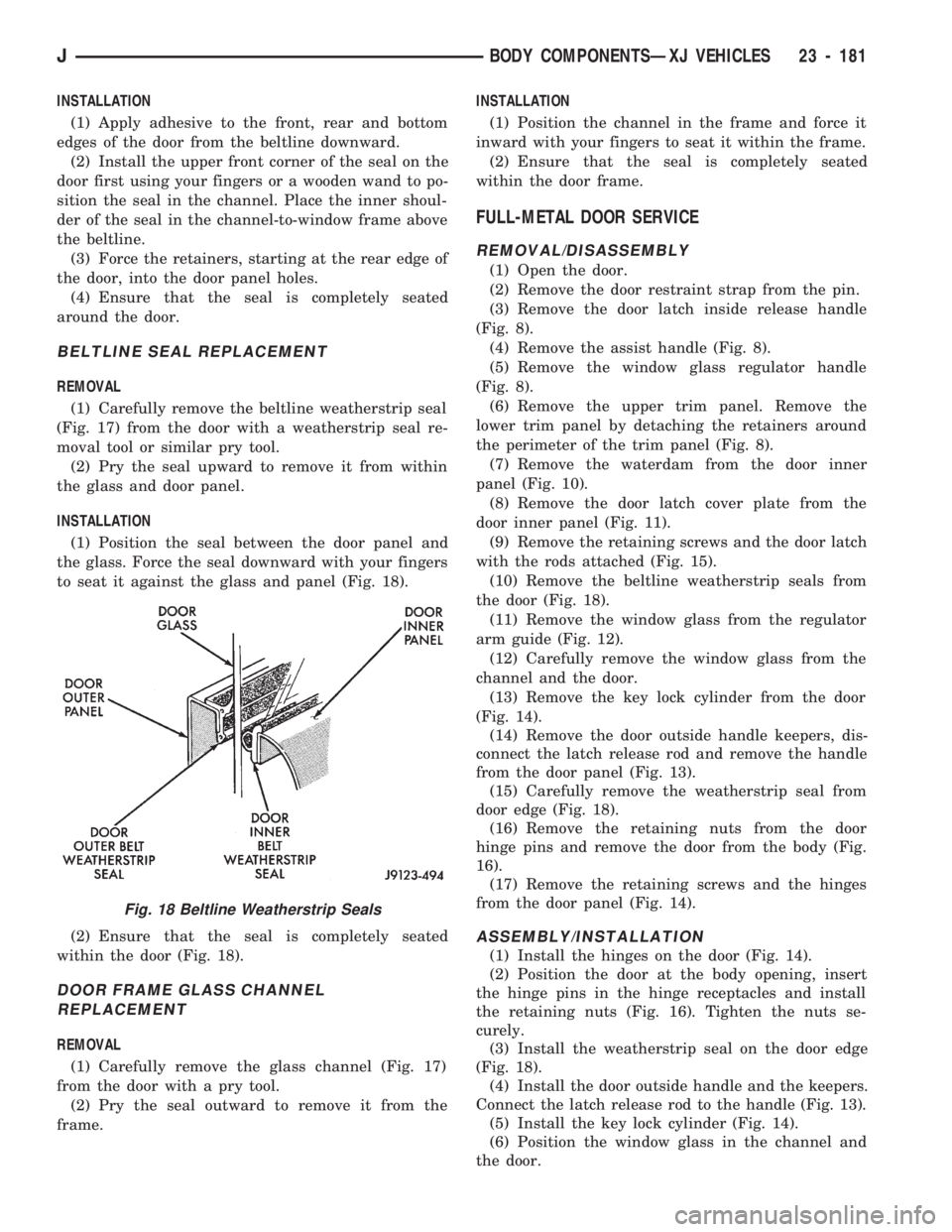
(1) Position the seal between the door panel and
the glass. Force the seal downward with your fingers
to seat it against the glass and panel (Fig. 18).
(2) Ensure that the seal is completely seated
within the door (Fig. 18).
DOOR FRAME GLASS CHANNEL
REPLACEMENT
REMOVAL
(1) Carefully remove the glass channel (Fig. 17)
from the door with a pry tool.
(2) Pry the seal outward to remove it from the
frame.INSTALLATION
(1) Position the channel in the frame and force it
inward with your fingers to seat it within the frame.
(2) Ensure that the seal is completely seated
within the door frame.
FULL-METAL DOOR SERVICE
REMOVAL/DISASSEMBLY
(1) Open the door.
(2) Remove the door restraint strap from the pin.
(3) Remove the door latch inside release handle
(Fig. 8).
(4) Remove the assist handle (Fig. 8).
(5) Remove the window glass regulator handle
(Fig. 8).
(6) Remove the upper trim panel. Remove the
lower trim panel by detaching the retainers around
the perimeter of the trim panel (Fig. 8).
(7) Remove the waterdam from the door inner
panel (Fig. 10).
(8) Remove the door latch cover plate from the
door inner panel (Fig. 11).
(9) Remove the retaining screws and the door latch
with the rods attached (Fig. 15).
(10) Remove the beltline weatherstrip seals from
the door (Fig. 18).
(11) Remove the window glass from the regulator
arm guide (Fig. 12).
(12) Carefully remove the window glass from the
channel and the door.
(13) Remove the key lock cylinder from the door
(Fig. 14).
(14) Remove the door outside handle keepers, dis-
connect the latch release rod and remove the handle
from the door panel (Fig. 13).
(15) Carefully remove the weatherstrip seal from
door edge (Fig. 18).
(16) Remove the retaining nuts from the door
hinge pins and remove the door from the body (Fig.
16).
(17) Remove the retaining screws and the hinges
from the door panel (Fig. 14).
ASSEMBLY/INSTALLATION
(1) Install the hinges on the door (Fig. 14).
(2) Position the door at the body opening, insert
the hinge pins in the hinge receptacles and install
the retaining nuts (Fig. 16). Tighten the nuts se-
curely.
(3) Install the weatherstrip seal on the door edge
(Fig. 18).
(4) Install the door outside handle and the keepers.
Connect the latch release rod to the handle (Fig. 13).
(5) Install the key lock cylinder (Fig. 14).
(6) Position the window glass in the channel and
the door.
Fig. 18 Beltline Weatherstrip Seals
JBODY COMPONENTSÐXJ VEHICLES 23 - 181
Page 1638 of 1784
FIXED WINDOW GLASS
INDEX
page page
Fixed Glass Water Leak Detection and Repair . 189
Hard Top Quarter Window Glass............ 188
Rearview Mirror......................... 183
Rearview Mirror Retaining Bracket........... 183
Service Information...................... 183Windshield Frame....................... 184
Windshield Frame Weatherstrip Seal......... 185
Windshield Glass........................ 185
Windshield Reveal Moulding............... 183
SERVICE INFORMATION
The following fixed window service information in-
cludes removal/installation procedures for the:
²windshield reveal moulding,
²rearview mirror,
²windshield frame,
²windshield frame weatherstrip seal,
²windshield glass (using both the short and the ex-
tended installation method), and
²hard top quarter (side) window glass.
WINDSHIELD REVEAL MOULDING
REMOVAL
(1) Disengage the reveal moulding around the pe-
rimeter of the windshield glass with an appropriate
tool.
(2) Remove the mouldings from the windshield
frame.
(3) Inspect the reveal moulding retainers. Replace
the moulding if it has broken, distorted or ineffective
retainers.
INSTALLATION
(1) Position the reveal mouldings on the wind-
shield frame.
(2) Attach the mouldings to the frame by tapping
each moulding with a rubber mallet to seat the re-
tainers.
REARVIEW MIRROR
REMOVAL/INSTALLATION
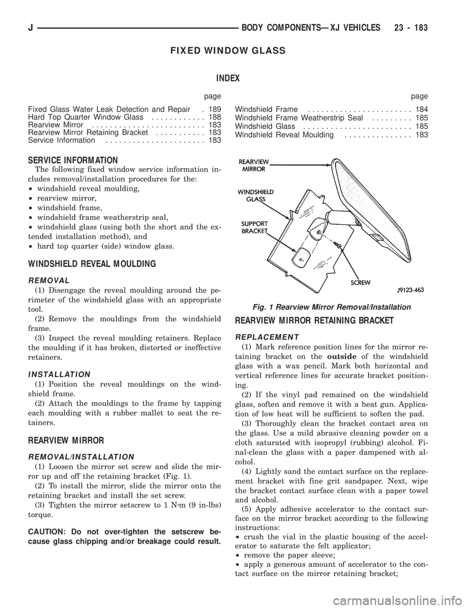
(1) Loosen the mirror set screw and slide the mir-
ror up and off the retaining bracket (Fig. 1).
(2) To install the mirror, slide the mirror onto the
retaining bracket and install the set screw.
(3) Tighten the mirror setscrew to 1 Nzm (9 in-lbs)
torque.
CAUTION: Do not over-tighten the setscrew be-
cause glass chipping and/or breakage could result.
REARVIEW MIRROR RETAINING BRACKET
REPLACEMENT
(1) Mark reference position lines for the mirror re-
taining bracket on theoutsideof the windshield
glass with a wax pencil. Mark both horizontal and
vertical reference lines for accurate bracket position-
ing.
(2) If the vinyl pad remained on the windshield
glass, soften and remove it with a heat gun. Applica-
tion of low heat will be sufficient to soften the pad.
(3) Thoroughly clean the bracket contact area on
the glass. Use a mild abrasive cleaning powder on a
cloth saturated with isopropyl (rubbing) alcohol. Fi-
nal-clean the glass with a paper dampened with al-
cohol.
(4) Lightly sand the contact surface on the replace-
ment bracket with fine grit sandpaper. Next, wipe
the bracket contact surface clean with a paper towel
and alcohol.
(5) Apply adhesive accelerator to the contact sur-
face on the mirror bracket according to the following
instructions:
²crush the vial in the plastic housing of the accel-
erator to saturate the felt applicator;
²remove the paper sleeve;
²apply a generous amount of accelerator to the con-
tact surface on the mirror retaining bracket;
Fig. 1 Rearview Mirror Removal/Installation
JBODY COMPONENTSÐXJ VEHICLES 23 - 183