1994 JEEP CHEROKEE mirror
[x] Cancel search: mirrorPage 1486 of 1784
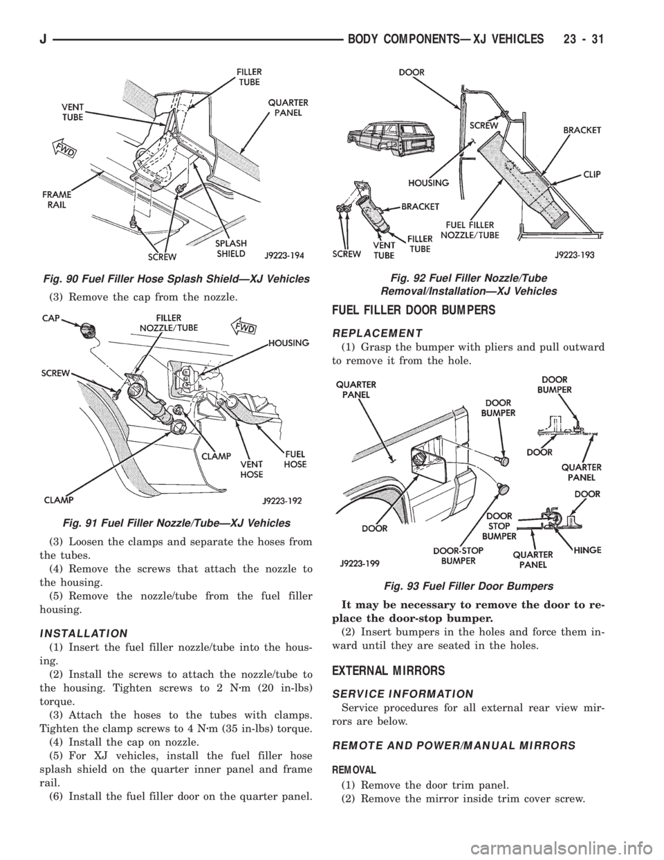
(3) Remove the cap from the nozzle.
(3) Loosen the clamps and separate the hoses from
the tubes.
(4) Remove the screws that attach the nozzle to
the housing.
(5) Remove the nozzle/tube from the fuel filler
housing.
INSTALLATION
(1) Insert the fuel filler nozzle/tube into the hous-
ing.
(2) Install the screws to attach the nozzle/tube to
the housing. Tighten screws to 2 Nzm (20 in-lbs)
torque.
(3) Attach the hoses to the tubes with clamps.
Tighten the clamp screws to 4 Nzm (35 in-lbs) torque.
(4) Install the cap on nozzle.
(5) For XJ vehicles, install the fuel filler hose
splash shield on the quarter inner panel and frame
rail.
(6) Install the fuel filler door on the quarter panel.
FUEL FILLER DOOR BUMPERS
REPLACEMENT
(1) Grasp the bumper with pliers and pull outward
to remove it from the hole.
It may be necessary to remove the door to re-
place the door-stop bumper.
(2) Insert bumpers in the holes and force them in-
ward until they are seated in the holes.
EXTERNAL MIRRORS
SERVICE INFORMATION
Service procedures for all external rear view mir-
rors are below.
REMOTE AND POWER/MANUAL MIRRORS
REMOVAL
(1) Remove the door trim panel.
(2) Remove the mirror inside trim cover screw.
Fig. 90 Fuel Filler Hose Splash ShieldÐXJ Vehicles
Fig. 91 Fuel Filler Nozzle/TubeÐXJ Vehicles
Fig. 92 Fuel Filler Nozzle/Tube
Removal/InstallationÐXJ Vehicles
Fig. 93 Fuel Filler Door Bumpers
JBODY COMPONENTSÐXJ VEHICLES 23 - 31
Page 1487 of 1784
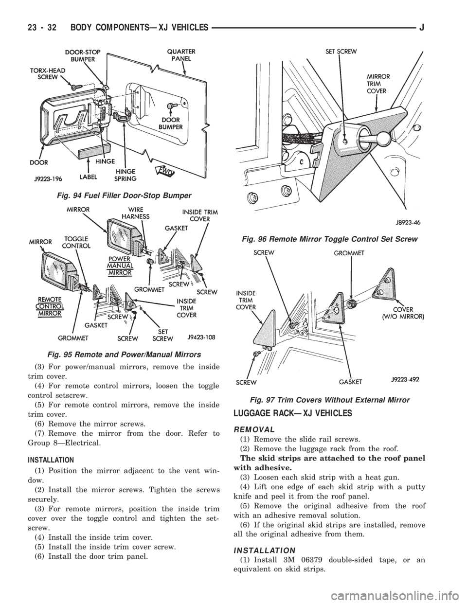
(3) For power/manual mirrors, remove the inside
trim cover.
(4) For remote control mirrors, loosen the toggle
control setscrew.
(5) For remote control mirrors, remove the inside
trim cover.
(6) Remove the mirror screws.
(7) Remove the mirror from the door. Refer to
Group 8ÐElectrical.
INSTALLATION
(1) Position the mirror adjacent to the vent win-
dow.
(2) Install the mirror screws. Tighten the screws
securely.
(3) For remote mirrors, position the inside trim
cover over the toggle control and tighten the set-
screw.
(4) Install the inside trim cover.
(5) Install the inside trim cover screw.
(6) Install the door trim panel.
LUGGAGE RACKÐXJ VEHICLES
REMOVAL
(1) Remove the slide rail screws.
(2) Remove the luggage rack from the roof.
The skid strips are attached to the roof panel
with adhesive.
(3) Loosen each skid strip with a heat gun.
(4) Lift one edge of each skid strip with a putty
knife and peel it from the roof panel.
(5) Remove the original adhesive from the roof
with an adhesive removal solution.
(6) If the original skid strips are installed, remove
all the original adhesive from them.
INSTALLATION
(1) Install 3M 06379 double-sided tape, or an
equivalent on skid strips.
Fig. 94 Fuel Filler Door-Stop Bumper
Fig. 95 Remote and Power/Manual Mirrors
Fig. 96 Remote Mirror Toggle Control Set Screw
Fig. 97 Trim Covers Without External Mirror
23 - 32 BODY COMPONENTSÐXJ VEHICLESJ
Page 1528 of 1784
FIXED WINDOW GLASS
INDEX
page page
Fixed Glass Water Leak Detection and Repair . . 83
Interior Rearview Mirror.................... 74
Interior Rearview Mirror Support Bracket
Replacement.......................... 75
Liftgate Window GlassÐXJ Vehicles.......... 81
Rear Quarter Vent Window GlassÐXJ Vehicles . 80Rear Quarter Window Glass/Rear Quarter
Plastic Insert ÐXJ Vehicles............... 80
Service Information....................... 73
Windshield Glass Replacement.............. 75
Windshield Reveal Moulding................ 73
Windshield Service Information.............. 75
SERVICE INFORMATION
The following service procedures include removal
and installation of the:
²windshield reveal moulding,
²interior rearview mirror,
²windshield glass (using both the short and the ex-
tended installation method),
²rear quarter vent window glass,
²rear quarter window glass,
²liftgate window glass,
²cab rear window, and
²leak detection and repair.
WINDSHIELD REVEAL MOULDING
REMOVAL
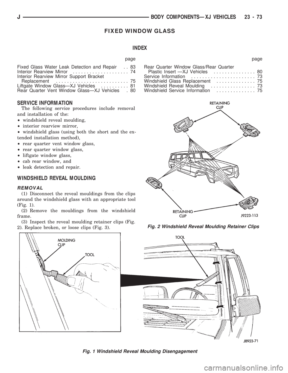
(1) Disconnect the reveal mouldings from the clips
around the windshield glass with an appropriate tool
(Fig. 1).
(2) Remove the mouldings from the windshield
frame.
(3) Inspect the reveal moulding retainer clips (Fig.
2). Replace broken, or loose clips (Fig. 3).
Fig. 1 Windshield Reveal Moulding Disengagement
Fig. 2 Windshield Reveal Moulding Retainer Clips
JBODY COMPONENTSÐXJ VEHICLES 23 - 73
Page 1529 of 1784
INSTALLATION
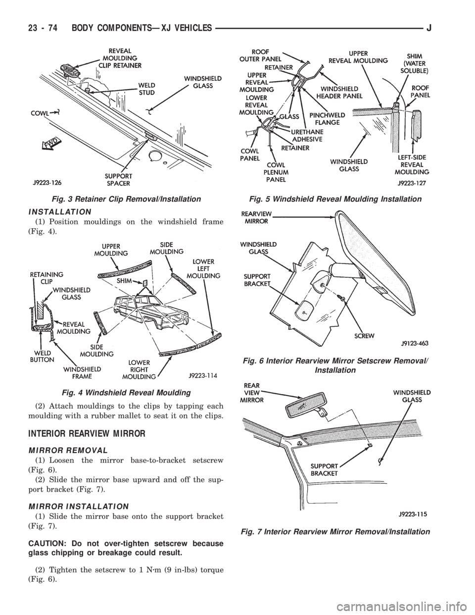
(1) Position mouldings on the windshield frame
(Fig. 4).
(2) Attach mouldings to the clips by tapping each
moulding with a rubber mallet to seat it on the clips.
INTERIOR REARVIEW MIRROR
MIRROR REMOVAL
(1) Loosen the mirror base-to-bracket setscrew
(Fig. 6).
(2) Slide the mirror base upward and off the sup-
port bracket (Fig. 7).
MIRROR INSTALLATION
(1) Slide the mirror base onto the support bracket
(Fig. 7).
CAUTION: Do not over-tighten setscrew because
glass chipping or breakage could result.
(2) Tighten the setscrew to 1 Nzm (9 in-lbs) torque
(Fig. 6).
Fig. 5 Windshield Reveal Moulding Installation
Fig. 6 Interior Rearview Mirror Setscrew Removal/
Installation
Fig. 7 Interior Rearview Mirror Removal/Installation
Fig. 3 Retainer Clip Removal/Installation
Fig. 4 Windshield Reveal Moulding
23 - 74 BODY COMPONENTSÐXJ VEHICLESJ
Page 1530 of 1784
INTERIOR REARVIEW MIRROR SUPPORT
BRACKET REPLACEMENT
PREPARATION
(1) Mark reference lines for the mirror support
bracket on the outside of windshield glass with a wax
pencil.
(2) If the vinyl pad remained on the windshield
glass, soften and remove it with a heat gun.
(3) Clean the support bracket surface area on the
glass. Use a mild abrasive cleaning powder on a cloth
saturated with isopropyl (rubbing) alcohol.
(4) Lightly sand the contact surface on the support
bracket with fine grit sandpaper. Wipe bracket con-
tact surface clean with a paper towel and alcohol.
INSTALLATION
(1) Apply adhesive to the act surface on the sup-
port bracket according as follows:
²crush the vial in the plastic housing of the accel-
erator to saturate the felt applicator;
²remove the paper sleeve;
²apply a generous amount of accelerator to the con-
tact surface on the mirror support bracket;
²do not touch the support bracket contact surface
after the accelerator has been applied.
²allow the accelerator to dry for at least five min-
utes; and
(2) Apply accelerator to the support bracket con-
tact surface on the windshield glass. Allow the accel-
erator to dry for one minute.
(3) Install the mirror bracket on the windshield
glass follows:
²apply one drop of adhesive at the center of support
bracket contact surface on windshield glass;
²immediately apply an even coat of adhesive to the
contact surface on the support bracket;
²align the support bracket with the position refer-
ence lines on the windshield glass, then
²press and hold the support bracket in-place for at
least one minute.
Ensure that the mirror support bracket is
correctly aligned because the adhesive will
cure rapidly.
(4) Allow the adhesive to cure for 8-10 minutes,
then remove any residue adhesive with an alcohol-
dampened cloth.
(5) Allow the adhesive to cure for an additional
8-10 minutes before installing the mirror base on the
support bracket.
WINDSHIELD SERVICE INFORMATION
URETHANE ADHESIVE BONDING
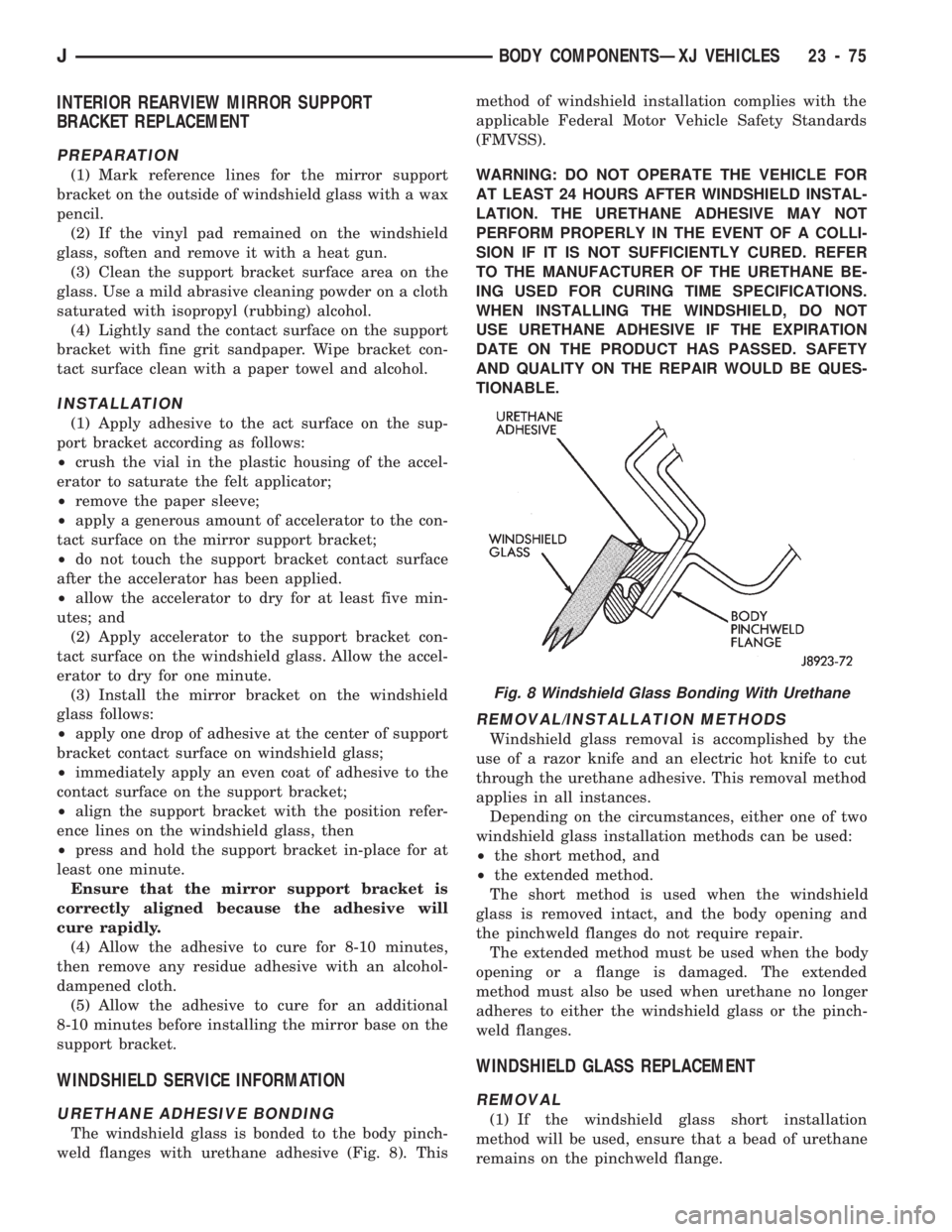
The windshield glass is bonded to the body pinch-
weld flanges with urethane adhesive (Fig. 8). Thismethod of windshield installation complies with the
applicable Federal Motor Vehicle Safety Standards
(FMVSS).
WARNING: DO NOT OPERATE THE VEHICLE FOR
AT LEAST 24 HOURS AFTER WINDSHIELD INSTAL-
LATION. THE URETHANE ADHESIVE MAY NOT
PERFORM PROPERLY IN THE EVENT OF A COLLI-
SION IF IT IS NOT SUFFICIENTLY CURED. REFER
TO THE MANUFACTURER OF THE URETHANE BE-
ING USED FOR CURING TIME SPECIFICATIONS.
WHEN INSTALLING THE WINDSHIELD, DO NOT
USE URETHANE ADHESIVE IF THE EXPIRATION
DATE ON THE PRODUCT HAS PASSED. SAFETY
AND QUALITY ON THE REPAIR WOULD BE QUES-
TIONABLE.
REMOVAL/INSTALLATION METHODS
Windshield glass removal is accomplished by the
use of a razor knife and an electric hot knife to cut
through the urethane adhesive. This removal method
applies in all instances.
Depending on the circumstances, either one of two
windshield glass installation methods can be used:
²the short method, and
²the extended method.
The short method is used when the windshield
glass is removed intact, and the body opening and
the pinchweld flanges do not require repair.
The extended method must be used when the body
opening or a flange is damaged. The extended
method must also be used when urethane no longer
adheres to either the windshield glass or the pinch-
weld flanges.
WINDSHIELD GLASS REPLACEMENT
REMOVAL
(1) If the windshield glass short installation
method will be used, ensure that a bead of urethane
remains on the pinchweld flange.
Fig. 8 Windshield Glass Bonding With Urethane
JBODY COMPONENTSÐXJ VEHICLES 23 - 75
Page 1531 of 1784
(2) Cover the interior and exterior body surface ar-
eas with a protective covering.
(3) Remove the windshield wiper arms, reveal
moulding, interior trim mouldings and rearview mir-
ror.
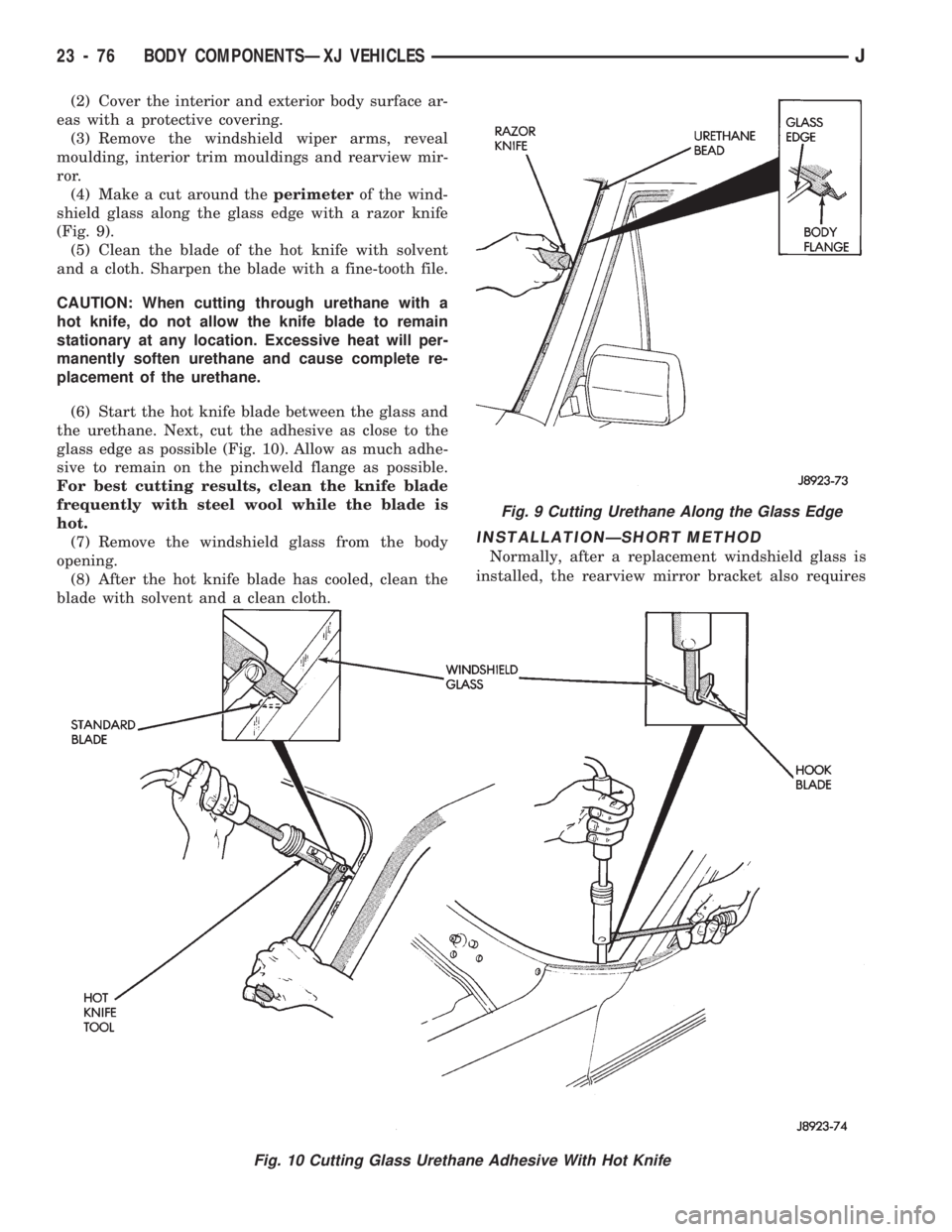
(4) Make a cut around theperimeterof the wind-
shield glass along the glass edge with a razor knife
(Fig. 9).
(5) Clean the blade of the hot knife with solvent
and a cloth. Sharpen the blade with a fine-tooth file.
CAUTION: When cutting through urethane with a
hot knife, do not allow the knife blade to remain
stationary at any location. Excessive heat will per-
manently soften urethane and cause complete re-
placement of the urethane.
(6) Start the hot knife blade between the glass and
the urethane. Next, cut the adhesive as close to the
glass edge as possible (Fig. 10). Allow as much adhe-
sive to remain on the pinchweld flange as possible.
For best cutting results, clean the knife blade
frequently with steel wool while the blade is
hot.
(7) Remove the windshield glass from the body
opening.
(8) After the hot knife blade has cooled, clean the
blade with solvent and a clean cloth.
INSTALLATIONÐSHORT METHOD
Normally, after a replacement windshield glass is
installed, the rearview mirror bracket also requires
Fig. 9 Cutting Urethane Along the Glass Edge
Fig. 10 Cutting Glass Urethane Adhesive With Hot Knife
23 - 76 BODY COMPONENTSÐXJ VEHICLESJ
Page 1533 of 1784
CAUTION: Avoid spilling or dripping primer on
painted surfaces. Clean spills or drips immediately.
The primer will damage the paint if it remains on
the surface for any length of time.
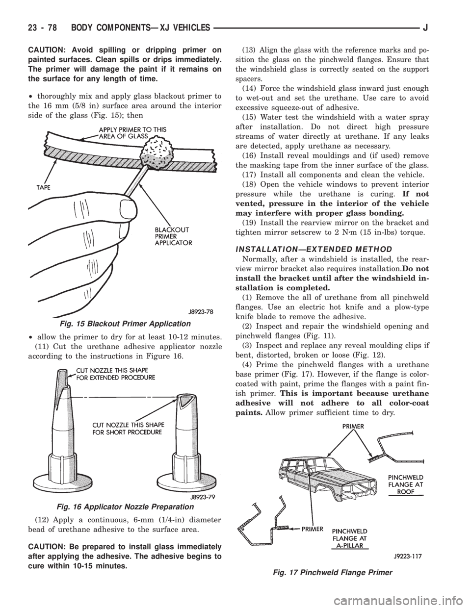
²thoroughly mix and apply glass blackout primer to
the 16 mm (5/8 in) surface area around the interior
side of the glass (Fig. 15); then
²allow the primer to dry for at least 10-12 minutes.
(11) Cut the urethane adhesive applicator nozzle
according to the instructions in Figure 16.
(12) Apply a continuous, 6-mm (1/4-in) diameter
bead of urethane adhesive to the surface area.
CAUTION: Be prepared to install glass immediately
after applying the adhesive. The adhesive begins to
cure within 10-15 minutes.(13) Align the glass with the reference marks and po-
sition the glass on the pinchweld flanges. Ensure that
the windshield glass is correctly seated on the support
spacers.
(14) Force the windshield glass inward just enough
to wet-out and set the urethane. Use care to avoid
excessive squeeze-out of adhesive.
(15) Water test the windshield with a water spray
after installation. Do not direct high pressure
streams of water directly at urethane. If any leaks
are detected, apply urethane as necessary.
(16) Install reveal mouldings and (if used) remove
the masking tape from the inner surface of the glass.
(17) Install all components and clean the vehicle.
(18) Open the vehicle windows to prevent interior
pressure while the urethane is curing.If not
vented, pressure in the interior of the vehicle
may interfere with proper glass bonding.
(19) Install the rearview mirror on the bracket and
tighten mirror setscrew to 2 Nzm (15 in-lbs) torque.
INSTALLATIONÐEXTENDED METHOD
Normally, after a windshield is installed, the rear-
view mirror bracket also requires installation.Do not
install the bracket until after the windshield in-
stallation is completed.
(1) Remove the all of urethane from all pinchweld
flanges. Use an electric hot knife and a plow-type
knife blade to remove the adhesive.
(2) Inspect and repair the windshield opening and
pinchweld flanges (Fig. 11).
(3) Inspect and replace any reveal moulding clips if
bent, distorted, broken or loose (Fig. 12).
(4) Prime the pinchweld flanges with a urethane
base primer (Fig. 17). However, if the flange is color-
coated with paint, prime the flanges with a paint fin-
ish primer.This is important because urethane
adhesive will not adhere to all color-coat
paints.Allow primer sufficient time to dry.
Fig. 15 Blackout Primer Application
Fig. 16 Applicator Nozzle Preparation
Fig. 17 Pinchweld Flange Primer
23 - 78 BODY COMPONENTSÐXJ VEHICLESJ
Page 1535 of 1784
(18) Install the rearview mirror on the bracket and
tighten the mirror setscrew to 2 Nzm (15 in-lbs) torque.
REAR QUARTER VENT WINDOW GLASSÐXJ
VEHICLES
REMOVAL
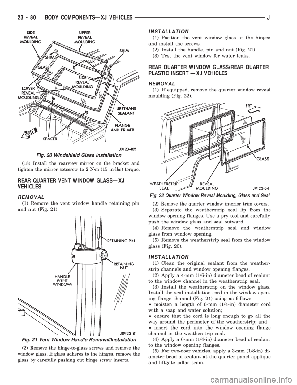
(1) Remove the vent window handle retaining pin
and nut (Fig. 21).
(2) Remove the hinge-to-glass screws and remove the
window glass. If glass adheres to the hinges, remove the
glass by carefully pushing out hinge screw inserts.
INSTALLATION
(1) Position the vent window glass at the hinges
and install the screws.
(2) Install the handle, pin and nut (Fig. 21).
(3) Test the vent window for water leaks.
REAR QUARTER WINDOW GLASS/REAR QUARTER
PLASTIC INSERT ÐXJ VEHICLES
REMOVAL
(1) If equipped, remove the quarter window reveal
moulding (Fig. 22).
(2) Remove the quarter window interior trim covers.
(3) Separate the weatherstrip seal lip from the
window opening flanges. Use a pry tool and carefully
push the window glass and seal outward.
(4) Remove the weatherstrip seal and window
glass from window opening.
(5) Remove the weatherstrip seal from the window
glass (Fig. 23).
INSTALLATION
(1) Clean the original sealant from the weather-
strip channels and window opening flanges.
(2) Apply a 4-mm (1/6-in) diameter bead of sealant
to the window channel in the weatherstrip seal.
(3) Install the weatherstrip on the window glass.
Install the seal installation cord in the window open-
ing flange channel (Fig. 24) using as follows:
²moisten a length of 6-mm (1/4-in) diameter cord
with a soap and water solution;
²ensure that the cord is long enough to go all the
way around the perimeter of the weatherstrip; and
²insert the cord into the window opening flange
channel in the weatherstrip seal.
(4) Apply a 6-mm (1/4-in) diameter bead of sealant
to the window opening flanges.
(5) For two-door vehicles, apply a 3-mm (1/8-in) di-
ameter bead of sealant at the quarter panel applique
and liftgate pillar seam.
Fig. 20 Windshield Glass Installation
Fig. 21 Vent Window Handle Removal/Installation
Fig. 22 Quarter Window Reveal Moulding, Glass and Seal
23 - 80 BODY COMPONENTSÐXJ VEHICLESJ