1994 JEEP CHEROKEE mirror
[x] Cancel search: mirrorPage 1543 of 1784
The reinforcement bracket is held on the
frame rail with two blind rivets.
(2) Remove the bracket and tow hook from frame
rail.
INSTALLATION
(1) Position bracket and tow hook on the frame
rail.
(2) Install bolts that attach tow hook bracket to
frame rail and reinforcement bracket. Tighten bolts
to 75 Nzm (55 ft-lbs) torque.
TRAILER HITCHES
CLASS III HITCHÐXJ VEHICLES
A class III weight-distributing/equalizer type hitch
can be used to tow a trailer:
²having a maximum gross weight of 5,000 lbs/2250
kg, and
²having a maximum tongue weight of 750 lbs/332
kg).
The following vehicle basic equipment is required
for class III trailer towing:
²P205/75R15 or larger tires;
²full size spare tire;
²trailer sway control;
²trailer tow wire harness and connector;
²heavy duty turn signal flasher element;
²heavy duty axle (with synthetic lubricant);²heavy duty cooling system;
²heavy duty generator/battery;
²auxiliary automatic transmission fluid cooler; and
²I-6, 4.0L engine.
Wide-angle type door mirrors are recommended but
not required.
WIRE HARNESS CONNECTORS
CLASS I HITCH CONNECTOR
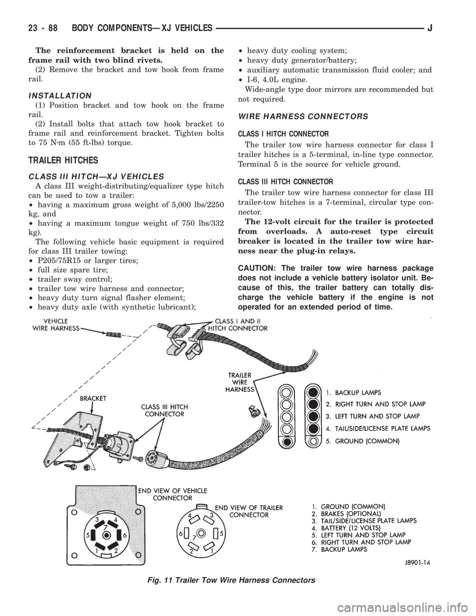
The trailer tow wire harness connector for class I
trailer hitches is a 5-terminal, in-line type connector.
Terminal 5 is the source for vehicle ground.
CLASS III HITCH CONNECTOR
The trailer tow wire harness connector for class III
trailer-tow hitches is a 7-terminal, circular type con-
nector.
The 12-volt circuit for the trailer is protected
from overloads. A auto-reset type circuit
breaker is located in the trailer tow wire har-
ness near the plug-in relays.
CAUTION: The trailer tow wire harness package
does not include a vehicle battery isolator unit. Be-
cause of this, the trailer battery can totally dis-
charge the vehicle battery if the engine is not
operated for an extended period of time.
Fig. 11 Trailer Tow Wire Harness Connectors
23 - 88 BODY COMPONENTSÐXJ VEHICLESJ
Page 1580 of 1784
PARKING BRAKE HANDLE COVERÐXJ
VEHICLES
REMOVAL
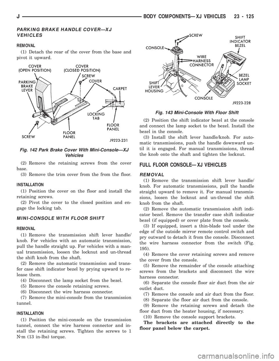
(1) Detach the rear of the cover from the base and
pivot it upward.
(2) Remove the retaining screws from the cover
base.
(3) Remove the trim cover from the from the floor.
INSTALLATION
(1) Position the cover on the floor and install the
retaining screws.
(2) Pivot the cover to the closed position and en-
gage the locking tab.
MINI-CONSOLE WITH FLOOR SHIFT
REMOVAL
(1) Remove the transmission shift lever handle/
knob. For vehicles with an automatic transmission,
pull the handle straight up. For vehicles with a man-
ual transmission, loosen the locknut and un-thread
the shift knob from the shaft.
(2) Remove the automatic transmission and trans-
fer case shift indicator bezel by prying upward to re-
lease them.
(4) Disconnect the lamp socket from the bezel.
(5) Remove the console retaining screws.
(6) Disconnect the wire harness connector.
(7) Remove the mini-console from the transmission
tunnel.
INSTALLATION
(1) Position the mini-console on the transmission
tunnel, connect the wire harness connector and in-
stall the retaining screws. Tighten the screws to 1
Nzm (13 in-lbs) torque.(2) Position the shift indicator bezel at the console
and connect the lamp socket to the bezel. Install the
bezel in the console.
(3) Install the shift lever handle/knob. For auto-
matic transmissions, push the handle downward un-
til it is engaged. For manual transmissions, thread
the knob onto the shaft and tighten the locknut.
FULL FLOOR CONSOLEÐXJ VEHICLES
REMOVAL
(1) Remove the transmission shift lever handle/
knob. For automatic transmissions, pull the handle
straight upward to remove it. For manual transmis-
sions, loosen the locknut and un-thread the shift
knob from the shaft.
(2) Remove the automatic transmission shift indi-
cator bezel. Remove the transfer case shift indicator
bezel (if equipped) or cover plate from the console.
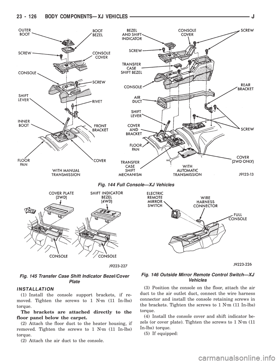
(3) If equipped, insert a thin-blade tool under the
edge of the outside mirror remote control switch and
pry outward to detach it from the console. Disconnect
the wire harness connector from the switch (Fig.
195).
(4) Remove the cover retaining screws and remove
the cover from the console.
(5) Remove the remainder of the console attaching
screws from the brackets and disconnect the wire
harness connector.
(6) Separate the console floor air duct from the air
outlet duct.
(7) Remove the console and air duct from the floor.
(8) Separate the floor air duct from the console.
(9) Remove the retaining screws and detach the
floor duct from the heater housing, if necessary.
(10) Remove the console support brackets.
The brackets are attached directly to the
floor panel below the carpet.
Fig. 142 Park Brake Cover With Mini-ConsoleÐXJ
Vehicles
Fig. 143 Mini-Console With Floor Shift
JBODY COMPONENTSÐXJ VEHICLES 23 - 125
Page 1581 of 1784
INSTALLATION
(1) Install the console support brackets, if re-
moved. Tighten the screws to 1 Nzm (11 In-lbs)
torque.
The brackets are attached directly to the
floor panel below the carpet.
(2) Attach the floor duct to the heater housing, if
removed. Tighten the screws to 1 Nzm (11 In-lbs)
torque.
(2) Attach the air duct to the console.(3) Position the console on the floor, attach the air
duct to the air outlet duct, connect the wire harness
connector and install the console retaining screws in
the brackets. Tighten the screws to 1 Nzm (11 In-lbs)
torque.
(4) Install the console cover and shift indicator be-
zels (or cover plate). Tighten the screws to 1 Nzm(11
In-lbs) torque.
(5) If equipped:
Fig. 146 Outside Mirror Remote Control SwitchÐXJ
Vehicles
Fig. 144 Full ConsoleÐXJ Vehicles
Fig. 145 Transfer Case Shift Indicator Bezel/Cover
Plate
23 - 126 BODY COMPONENTSÐXJ VEHICLESJ
Page 1582 of 1784
²connect the wire harness connector to the outside
mirror remote control switch,
²insert the switch into the console hole, and
²push inward to engage the retaining clips.
(6) Install the shift lever handle/knob.
JACK STORAGEÐXJ VEHICLES
SERVICE INFORMATION
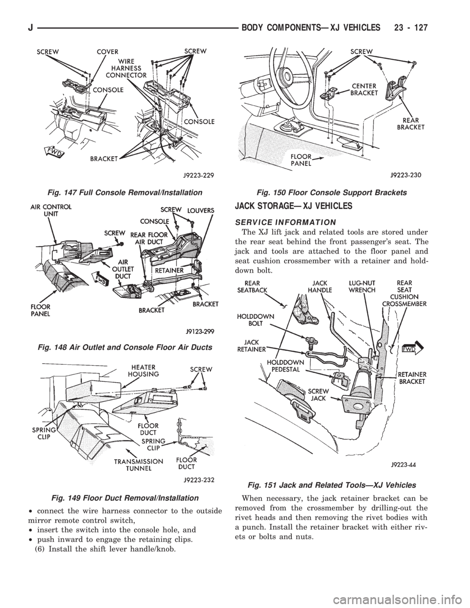
The XJ lift jack and related tools are stored under
the rear seat behind the front passenger's seat. The
jack and tools are attached to the floor panel and
seat cushion crossmember with a retainer and hold-
down bolt.
When necessary, the jack retainer bracket can be
removed from the crossmember by drilling-out the
rivet heads and then removing the rivet bodies with
a punch. Install the retainer bracket with either riv-
ets or bolts and nuts.
Fig. 147 Full Console Removal/Installation
Fig. 148 Air Outlet and Console Floor Air Ducts
Fig. 149 Floor Duct Removal/Installation
Fig. 150 Floor Console Support Brackets
Fig. 151 Jack and Related ToolsÐXJ Vehicles
JBODY COMPONENTSÐXJ VEHICLES 23 - 127
Page 1589 of 1784
EXTERIOR COMPONENTS
INDEX
page page
Battery Tray........................... 140
Body Extension Panels and FasciasÐYJ
Renegade Vehicles..................... 147
Body Side Step Moulding................. 145
Body Stripes/Decals..................... 153
Cowl Grille and Screen................... 139
Cowl Weatherstrip Seal................... 139
Exterior Nameplates (Adhesive-Backed)....... 158
External Spare/Wheel Tire Carrier........... 172
Fender Flare........................... 144
Fender Inner Splash Shields............... 147
Fender Splash Aprons.................... 147
Fenders............................... 141
Fog LampÐYJ Renegade Vehicles.......... 150
Front Fascia and Skid PlateÐYJ Renegade
Vehicles............................. 148
Front Fender Extension PanelÐYJ Renegade
Vehicles............................. 149
Fuel Filler Protector/Nozzle................ 158
Half Metal Door Mirror (External)............ 158
Hard Top Liftgate Glass.................. 162
Hard Top Repair........................ 165
Hard Top Roof Vent..................... 165
Hard Top Service....................... 164
Hard Top Service Information.............. 164Hood................................. 137
Hood Alignment......................... 138
Hood Insulator Panel..................... 138
Hood Safety Latch....................... 139
Liftgate Glass Weatherstrip Seal Replacement . . 163
Radiator Grille Applique................... 134
Rear Fascia and Skid PlateÐYJ Renegade
Vehicles............................. 152
Rear Quarter Extension PanelÐYJ Renegade
Vehicles............................. 151
Rocker Extension PanelÐYJ Renegade
Vehicles............................. 150
Soft Top Service........................ 167
Soft Top Service Information............... 166
Sport Bar............................. 171
Tailgate Adjustment...................... 160
Tailgate Hinge.......................... 159
Tailgate Latch and Release Handle.......... 160
Tailgate Latch Striker..................... 161
Tailgate Lock Cylinder.................... 160
Tailgate Service......................... 159
Tailgate Service Information................ 159
Tailgate Weatherstrip Seal................. 161
Wheelhouse Splash Liners................ 146
RADIATOR GRILLE APPLIQUE
REMOVAL
(1) Raise the hood.
(2) Remove the headlamp bezels (Fig. 1).
(3) Remove the headlamp bulb retainer screws
(Fig. 2).
(4) Disconnect and remove the headlamps and
buckets as a unit (Fig. 2).
(5) Remove the parking lamp retaining screws
(Fig. 2).
(6) Disconnect the wire harness connectors and re-
move the parking lamps (Fig. 2).
(7) Remove the front crossmember cover.
(8) Remove the retaining screws and the bumper
inserts at the top of the grille panel (Fig. 1).
(9) Detach the grille applique from the grille panel
(Fig. 1).
(10) Remove the double faced foam adhesive tape
at the bottom of the grille applique (Fig. 1).
INSTALLATION
(1) Install double faced foam tape at the bottom,
interior side of the grille applique (Fig. 1).
(2) Position the grille applique over the grille
panel and press inward along the bottom where the
tape is located (Fig. 1).
(3) Install the grille applique retaining screws and
the bumper inserts (Fig. 1).(4) Connect the wire harness connectors and posi-
tion the headlamp buckets and headlamps in the
grille panel (Fig. 2).
(5) Install the headlamp bulb retainer and the
screws (Fig. 1). Tighten the screws to 2 Nzm (18 in-
lbs) torque.
(6) Install the headlamp bezels and the retaining
screws (Fig. 1). Tighten the screws securely.
(7) Connect the wire harness connectors and in-
stall the parking lamps (Fig. 2).
(8) Install the parking lamp retaining screws.
Tighten the screws to 2 Nzm (18 in-lbs) torque.
(9) Close the hood.
(10) Install the front crossmember cover.
23 - 134 BODY COMPONENTSÐXJ VEHICLESJ
Page 1613 of 1784
area and re-align stripe/decal with panel character
line.Do not lift the tape stripe/decal if only a
few air bubbles exist.
(10) Where applicable, allow 12 mm (1/2 in) extra
tape stripe/decal to extend beyond the edges to be
folded over.
(11) Fold the excess tape stripe/decal back onto in-
side flange area.Use care to avoid trapping air
under the tape stripe/decal.Where necessary,
trim excess tape stripe/decal.
(12) Inspect tape installation with reflected light to
detect any defects that could have developed during
the installation.
(13) Remove all air and moisture bubbles from the
tape stripe/decal with a needle or pin.
(14) Install any removed components and clean the
vehicle as necessary.
EXTERIOR NAMEPLATES (ADHESIVE-BACKED)
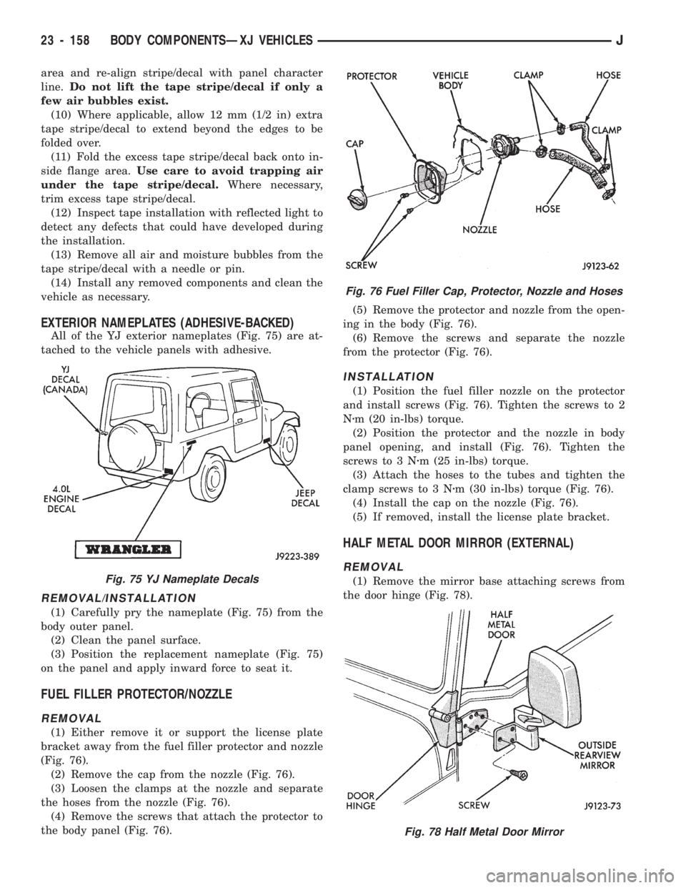
All of the YJ exterior nameplates (Fig. 75) are at-
tached to the vehicle panels with adhesive.
REMOVAL/INSTALLATION
(1) Carefully pry the nameplate (Fig. 75) from the
body outer panel.
(2) Clean the panel surface.
(3) Position the replacement nameplate (Fig. 75)
on the panel and apply inward force to seat it.
FUEL FILLER PROTECTOR/NOZZLE
REMOVAL
(1) Either remove it or support the license plate
bracket away from the fuel filler protector and nozzle
(Fig. 76).
(2) Remove the cap from the nozzle (Fig. 76).
(3) Loosen the clamps at the nozzle and separate
the hoses from the nozzle (Fig. 76).
(4) Remove the screws that attach the protector to
the body panel (Fig. 76).(5) Remove the protector and nozzle from the open-
ing in the body (Fig. 76).
(6) Remove the screws and separate the nozzle
from the protector (Fig. 76).
INSTALLATION
(1) Position the fuel filler nozzle on the protector
and install screws (Fig. 76). Tighten the screws to 2
Nzm (20 in-lbs) torque.
(2) Position the protector and the nozzle in body
panel opening, and install (Fig. 76). Tighten the
screws to 3 Nzm (25 in-lbs) torque.
(3) Attach the hoses to the tubes and tighten the
clamp screws to 3 Nzm (30 in-lbs) torque (Fig. 76).
(4) Install the cap on the nozzle (Fig. 76).
(5) If removed, install the license plate bracket.
HALF METAL DOOR MIRROR (EXTERNAL)
REMOVAL
(1) Remove the mirror base attaching screws from
the door hinge (Fig. 78).
Fig. 76 Fuel Filler Cap, Protector, Nozzle and Hoses
Fig. 78 Half Metal Door Mirror
Fig. 75 YJ Nameplate Decals
23 - 158 BODY COMPONENTSÐXJ VEHICLESJ
Page 1614 of 1784
(2) Remove the mirror from the door hinge (Fig.
78).
INSTALLATION
(1) Clean the door hinge-mirror base contact sur-
face.
(2) Position the mirror base at the door hinge (Fig.
78).
(3) Install the mirror base attaching screws in the
door hinge (Fig. 78). Tighten the attaching screws to
11 Nzm (96 in-lbs) torque.
TAILGATE SERVICE INFORMATION
The following tailgate service procedures include:
²tailgate removal/installation,
²tailgate hinge replacement,
²tailgate adjustment,
²tailgate latch removal/installation,
²tailgate lock cylinder removal/installation,
²tailgate latch striker removal/installation, and
²tailgate seal replacement.
TAILGATE SERVICE
REMOVAL
(1) For YJ Renegade vehicles:
²open the tailgate;
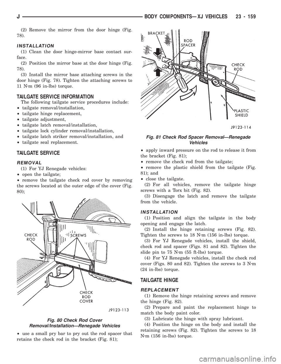
²remove the tailgate check rod cover by removing
the screws located at the outer edge of the cover (Fig.
80);
²use a small pry bar to pry out the rod spacer that
retains the check rod in the bracket (Fig. 81);²apply inward pressure on the rod to release it from
the bracket (Fig. 81);
²remove the check rod from the tailgate;
²remove the plastic shield from the tailgate (Fig.
81); and
²close the tailgate.
(2) For all vehicles, remove the tailgate hinge
screws with a Torx bit (Fig. 82).
(3) Disengage the latch and remove the tailgate
from the vehicle.
INSTALLATION
(1) Position and align the tailgate in the body
opening and engage the latch.
(2) Install the hinge retaining screws (Fig. 82).
Tighten the screws to 18 Nzm (156 in-lbs) torque.
(3) For YJ Renegade vehicles, install the shield,
check rod and spacer (Figs. 81 and 82). Tighten the
slide pin to 75 Nzm (55 ft-lbs) torque.
(4) For YJ Renegade vehicles, install the check rod
cover (Figs. 80 and 82). Tighten the screws to 3 Nzm
(24 in-lbs) torque.
TAILGATE HINGE
REPLACEMENT
(1) Remove the hinge retaining screws and remove
the hinge (Fig. 82).
(2) Prepare and paint the replacement hinge to
match the body paint color.
(3) Lubricate the hinge with spray lubricant.
(4) Position the hinge on the body and install the
retaining screws (Fig. 82). Tighten the screws to 18
Nzm (156 in-lbs) torque.
Fig. 80 Check Rod Cover
Removal/InstallationÐRenegade Vehicles
Fig. 81 Check Rod Spacer RemovalÐRenegade
Vehicles
JBODY COMPONENTSÐXJ VEHICLES 23 - 159
Page 1638 of 1784
FIXED WINDOW GLASS
INDEX
page page
Fixed Glass Water Leak Detection and Repair . 189
Hard Top Quarter Window Glass............ 188
Rearview Mirror......................... 183
Rearview Mirror Retaining Bracket........... 183
Service Information...................... 183Windshield Frame....................... 184
Windshield Frame Weatherstrip Seal......... 185
Windshield Glass........................ 185
Windshield Reveal Moulding............... 183
SERVICE INFORMATION
The following fixed window service information in-
cludes removal/installation procedures for the:
²windshield reveal moulding,
²rearview mirror,
²windshield frame,
²windshield frame weatherstrip seal,
²windshield glass (using both the short and the ex-
tended installation method), and
²hard top quarter (side) window glass.
WINDSHIELD REVEAL MOULDING
REMOVAL
(1) Disengage the reveal moulding around the pe-
rimeter of the windshield glass with an appropriate
tool.
(2) Remove the mouldings from the windshield
frame.
(3) Inspect the reveal moulding retainers. Replace
the moulding if it has broken, distorted or ineffective
retainers.
INSTALLATION
(1) Position the reveal mouldings on the wind-
shield frame.
(2) Attach the mouldings to the frame by tapping
each moulding with a rubber mallet to seat the re-
tainers.
REARVIEW MIRROR
REMOVAL/INSTALLATION
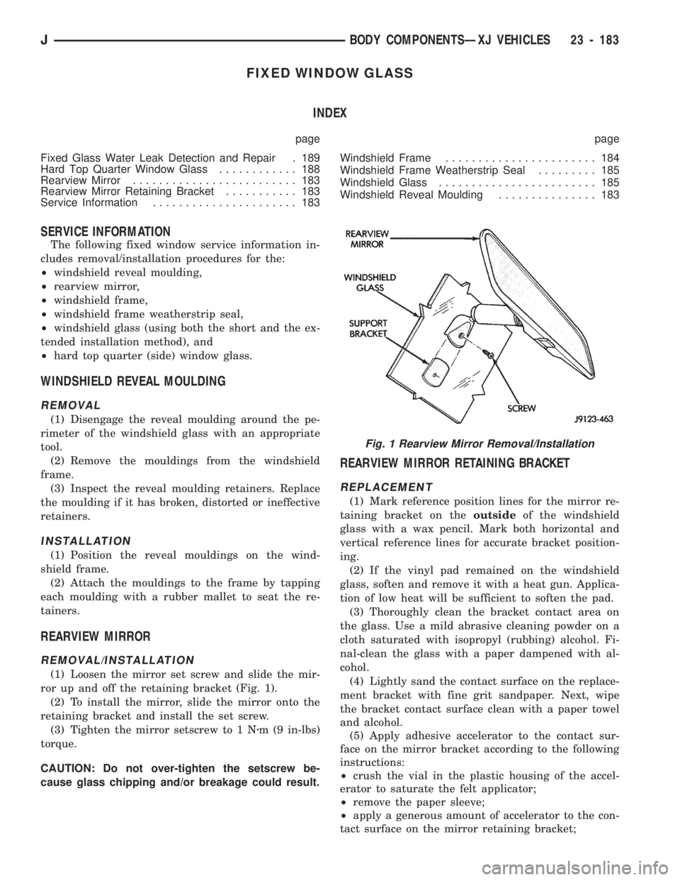
(1) Loosen the mirror set screw and slide the mir-
ror up and off the retaining bracket (Fig. 1).
(2) To install the mirror, slide the mirror onto the
retaining bracket and install the set screw.
(3) Tighten the mirror setscrew to 1 Nzm (9 in-lbs)
torque.
CAUTION: Do not over-tighten the setscrew be-
cause glass chipping and/or breakage could result.
REARVIEW MIRROR RETAINING BRACKET
REPLACEMENT
(1) Mark reference position lines for the mirror re-
taining bracket on theoutsideof the windshield
glass with a wax pencil. Mark both horizontal and
vertical reference lines for accurate bracket position-
ing.
(2) If the vinyl pad remained on the windshield
glass, soften and remove it with a heat gun. Applica-
tion of low heat will be sufficient to soften the pad.
(3) Thoroughly clean the bracket contact area on
the glass. Use a mild abrasive cleaning powder on a
cloth saturated with isopropyl (rubbing) alcohol. Fi-
nal-clean the glass with a paper dampened with al-
cohol.
(4) Lightly sand the contact surface on the replace-
ment bracket with fine grit sandpaper. Next, wipe
the bracket contact surface clean with a paper towel
and alcohol.
(5) Apply adhesive accelerator to the contact sur-
face on the mirror bracket according to the following
instructions:
²crush the vial in the plastic housing of the accel-
erator to saturate the felt applicator;
²remove the paper sleeve;
²apply a generous amount of accelerator to the con-
tact surface on the mirror retaining bracket;
Fig. 1 Rearview Mirror Removal/Installation
JBODY COMPONENTSÐXJ VEHICLES 23 - 183