1994 JEEP CHEROKEE mirror
[x] Cancel search: mirrorPage 1639 of 1784
²do not touch the retaining bracket contact surface
after the accelerator has been applied.
²allow the accelerator to dry for at least five min-
utes; and
(6) Apply accelerator to bracket contact surface on
the windshield glass. Allow the accelerator to dry for
one minute. Do not touch the glass contact surface
after the accelerator has been applied.
(7) Install the mirror retaining bracket according
to the following instructions:
²apply one drop of adhesive at the center of the re-
taining bracket contact surface on the windshield
glass;
²immediately apply an even coat of adhesive to the
contact surface on the retaining bracket;
²align the retaining bracket with the position refer-
ence lines on the windshield glass, then
²press and hold the retaining bracket in-place for at
least one minute.
Ensure that the mirror retaining bracket is
correctly aligned because the adhesive will
cure rapidly.
(8) Allow the adhesive to cure for 8-10 minutes,
then remove any residue adhesive with an alcohol
dampened cloth.
(9) Allow the adhesive to cure for an additional
8-10 minutes before installing the mirror on the re-
taining bracket (Fig. 1).
WINDSHIELD FRAME
SERVICE INFORMATION
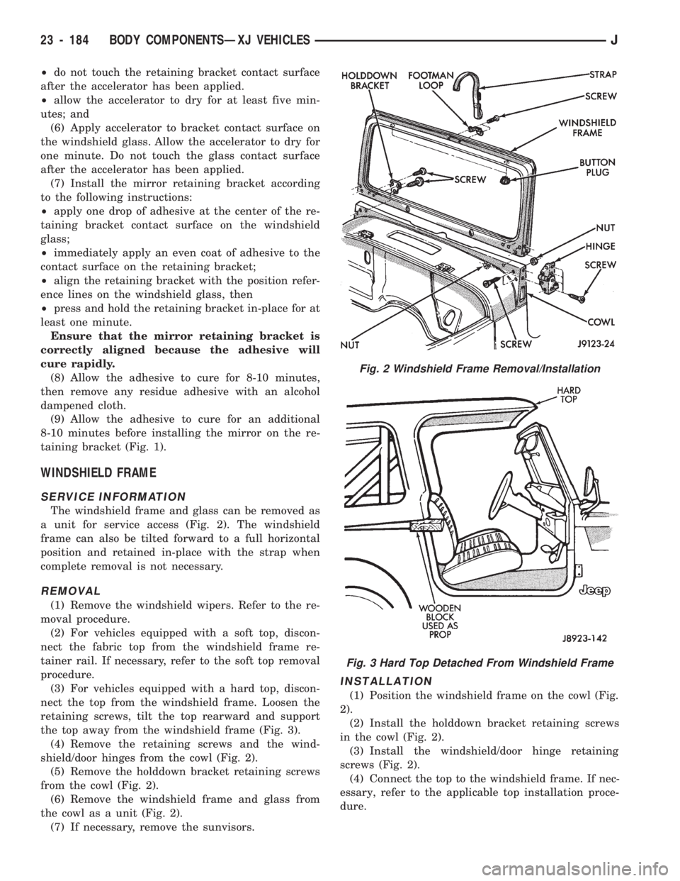
The windshield frame and glass can be removed as
a unit for service access (Fig. 2). The windshield
frame can also be tilted forward to a full horizontal
position and retained in-place with the strap when
complete removal is not necessary.
REMOVAL
(1) Remove the windshield wipers. Refer to the re-
moval procedure.
(2) For vehicles equipped with a soft top, discon-
nect the fabric top from the windshield frame re-
tainer rail. If necessary, refer to the soft top removal
procedure.
(3) For vehicles equipped with a hard top, discon-
nect the top from the windshield frame. Loosen the
retaining screws, tilt the top rearward and support
the top away from the windshield frame (Fig. 3).
(4) Remove the retaining screws and the wind-
shield/door hinges from the cowl (Fig. 2).
(5) Remove the holddown bracket retaining screws
from the cowl (Fig. 2).
(6) Remove the windshield frame and glass from
the cowl as a unit (Fig. 2).
(7) If necessary, remove the sunvisors.
INSTALLATION
(1) Position the windshield frame on the cowl (Fig.
2).
(2) Install the holddown bracket retaining screws
in the cowl (Fig. 2).
(3) Install the windshield/door hinge retaining
screws (Fig. 2).
(4) Connect the top to the windshield frame. If nec-
essary, refer to the applicable top installation proce-
dure.
Fig. 2 Windshield Frame Removal/Installation
Fig. 3 Hard Top Detached From Windshield Frame
23 - 184 BODY COMPONENTSÐXJ VEHICLESJ
Page 1641 of 1784
When the windshield glass short installation
method is used, an even, uniform bead of ure-
thane adhesive must remain on the frame
pinchweld flanges. This adhesive bead is
needed as a base for the replacement glass.
If the extended installation method is used,
the original windshield interior trim moulding
must be removed and discarded. The adhesive
cannot be removed from the original moulding.
REMOVAL
(1) Cover body surface areas with protective cover-
ing to avoid paint damage and extra clean-up time.
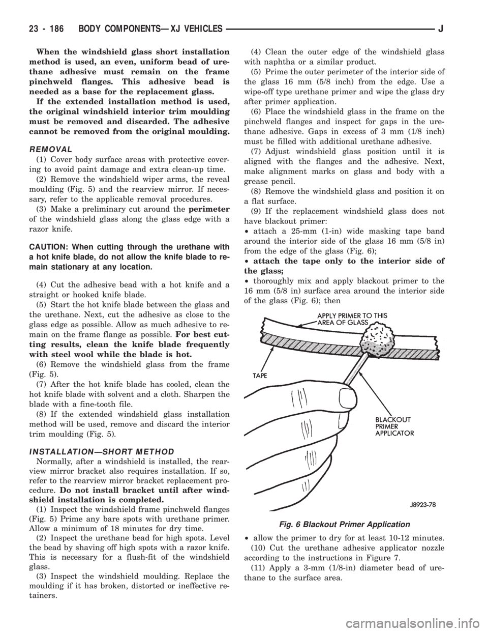
(2) Remove the windshield wiper arms, the reveal
moulding (Fig. 5) and the rearview mirror. If neces-
sary, refer to the applicable removal procedures.
(3) Make a preliminary cut around theperimeter
of the windshield glass along the glass edge with a
razor knife.
CAUTION: When cutting through the urethane with
a hot knife blade, do not allow the knife blade to re-
main stationary at any location.
(4) Cut the adhesive bead with a hot knife and a
straight or hooked knife blade.
(5) Start the hot knife blade between the glass and
the urethane. Next, cut the adhesive as close to the
glass edge as possible. Allow as much adhesive to re-
main on the frame flange as possible.For best cut-
ting results, clean the knife blade frequently
with steel wool while the blade is hot.
(6) Remove the windshield glass from the frame
(Fig. 5).
(7) After the hot knife blade has cooled, clean the
hot knife blade with solvent and a cloth. Sharpen the
blade with a fine-tooth file.
(8) If the extended windshield glass installation
method will be used, remove and discard the interior
trim moulding (Fig. 5).
INSTALLATIONÐSHORT METHOD
Normally, after a windshield is installed, the rear-
view mirror bracket also requires installation. If so,
refer to the rearview mirror bracket replacement pro-
cedure.Do not install bracket until after wind-
shield installation is completed.
(1) Inspect the windshield frame pinchweld flanges
(Fig. 5) Prime any bare spots with urethane primer.
Allow a minimum of 18 minutes for dry time.
(2) Inspect the urethane bead for high spots. Level
the bead by shaving off high spots with a razor knife.
This is necessary for a flush-fit of the windshield
glass.
(3) Inspect the windshield moulding. Replace the
moulding if it has broken, distorted or ineffective re-
tainers.(4) Clean the outer edge of the windshield glass
with naphtha or a similar product.
(5) Prime the outer perimeter of the interior side of
the glass 16 mm (5/8 inch) from the edge. Use a
wipe-off type urethane primer and wipe the glass dry
after primer application.
(6) Place the windshield glass in the frame on the
pinchweld flanges and inspect for gaps in the ure-
thane adhesive. Gaps in excess of 3 mm (1/8 inch)
must be filled with additional urethane adhesive.
(7) Adjust windshield glass position until it is
aligned with the flanges and the adhesive. Next,
make alignment marks on glass and body with a
grease pencil.
(8) Remove the windshield glass and position it on
a flat surface.
(9) If the replacement windshield glass does not
have blackout primer:
²attach a 25-mm (1-in) wide masking tape band
around the interior side of the glass 16 mm (5/8 in)
from the edge of the glass (Fig. 6);
²attach the tape only to the interior side of
the glass;
²thoroughly mix and apply blackout primer to the
16 mm (5/8 in) surface area around the interior side
of the glass (Fig. 6); then
²allow the primer to dry for at least 10-12 minutes.
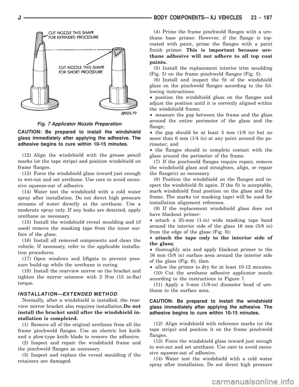
(10) Cut the urethane adhesive applicator nozzle
according to the instructions in Figure 7.
(11) Apply a 3-mm (1/8-in) diameter bead of ure-
thane to the surface area.
Fig. 6 Blackout Primer Application
23 - 186 BODY COMPONENTSÐXJ VEHICLESJ
Page 1642 of 1784
CAUTION: Be prepared to install the windshield
glass immediately after applying the adhesive. The
adhesive begins to cure within 10-15 minutes.
(12) Align the windshield with the grease pencil
marks (or the tape strips) and position windshield on
frame flanges.
(13) Force the windshield glass inward just enough
to wet-out and set urethane. Use care to avoid exces-
sive squeeze-out of adhesive.
(14) Water test the windshield with a cold water
spray after installation. Do not direct high pressure
streams of water directly at the urethane. Use a
moderate spray only. If any leaks are detected, apply
urethane as necessary.
(15) Install the windshield reveal moulding and (if
used) remove the masking tape from the inner sur-
face of the glass.
(16) Install all removed components and clean the
vehicle. If necessary, refer to the applicable installa-
tion procedures.
(17) Open windows and liftgate to prevent pres-
sure build-up while the urethane is curing.
(18) Install the rearview mirror on the bracket and
tighten the mirror setscrew with 2 Nzm (15 in-lbs)
torque.
INSTALLATIONÐEXTENDED METHOD
Normally, after a windshield is installed, the rear-
view mirror bracket also requires installation.Do not
install the bracket until after the windshield in-
stallation is completed.
(1) Remove all of the original urethane from all the
frame pinchweld flanges. Use an electric hot knife
and a plow-type knife blade to remove the adhesive.
(2) Inspect and repair the windshield frame and
the pinchweld flanges as necessary.
(3) Inspect and replace the reveal moulding if the
retainers are damaged.(4) Prime the frame pinchweld flanges with a ure-
thane base primer. However, if the flange is top-
coated with paint, prime the flanges with a paint
finish primer.This is important because ure-
thane adhesive will not adhere to all top coat
paints.
(5) Install the replacement interior trim moulding
(Fig. 5) on the frame pinchweld flanges (Fig. 5).
(6) Install and inspect the fit of the windshield
glass on the pinchweld flanges according to the fol-
lowing instructions:
²position the windshield glass on the flanges and
adjust the position until it is correctly aligned within
the windshield frame;
²measure the gap between the frame and the glass
around the entire perimeter of the glass and the
flange;
²the gap should be at least 3 mm (1/8 in) but no
more than 6 mm (1/4 in) at any point around the pe-
rimeter; and
²the flanges should in complete contact with the
glass around the perimeter of the frame.
(7) If the pinchweld flanges require repair, remove
the windshield glass and straighten, align, or repair
the flange(s) as necessary.
(8) Position the windshield on the flanges and in-
spect the windshield fit again. If the fit is acceptable,
mark windshield final position on the glass and the
frame. The marks (or masking tape) will be used for
installation alignment reference.
(9) If the replacement windshield glass does not
have blackout primer:
²attach a 25-mm (1-in) wide masking tape band
around the interior side of the glass 16 mm (5/8 in)
from the edge of the glass (Fig. 6);
²attach the tape only to the interior side of
the glass;
²thoroughly mix and apply blackout primer to the
16 mm (5/8 in) surface area around the interior side
of the glass (Fig. 6); then
²allow the primer to dry for at least 10-12 minutes.
(10) Cut the urethane adhesive applicator nozzle
according to the instructions in Figure 7.
(11) Apply a 3-mm (1/8-in) diameter bead of ure-
thane to the surface area.
CAUTION: Be prepared to install the windshield
glass immediately after applying the adhesive. The
adhesive begins to cure within 10-15 minutes.
(12) Align windshield with reference marks (or the
tape strips) and position it on the frame pinchweld
flanges.
(13) Force the windshield glass inward just enough
to wet-out and set urethane. Use care to avoid exces-
sive squeeze-out of adhesive.
(14) Water test the windshield with a cold water
spray after installation. Do not direct high pressure
Fig. 7 Applicator Nozzle Preparation
JBODY COMPONENTSÐXJ VEHICLES 23 - 187
Page 1643 of 1784
streams of water directly at the urethane. Use a
moderate spray only. If any leaks are detected, apply
urethane as necessary.
(15) Install the windshield reveal moulding and (if
used) remove the masking tape from the inner sur-
face of the glass.
(16) Install all the other previously removed com-
ponents and clean the vehicle. If necessary, refer to
the applicable installation procedures.
(17) Open windows and liftgate to prevent pres-
sure build-up while the urethane is curing.
(18) Install the rearview mirror on the bracket and
tighten the mirror setscrew to 2 Nzm (15 in-lbs)
torque.
HARD TOP QUARTER WINDOW GLASS
REMOVAL
(1) Cover surface areas with protective covering to
avoid paint damage and extra clean-up time.
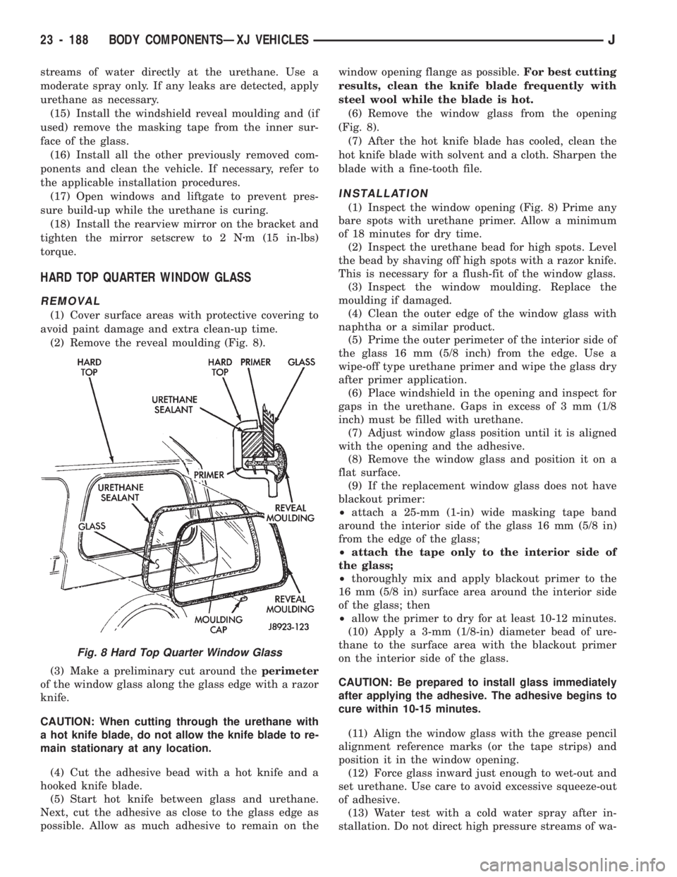
(2) Remove the reveal moulding (Fig. 8).
(3) Make a preliminary cut around theperimeter
of the window glass along the glass edge with a razor
knife.
CAUTION: When cutting through the urethane with
a hot knife blade, do not allow the knife blade to re-
main stationary at any location.
(4) Cut the adhesive bead with a hot knife and a
hooked knife blade.
(5) Start hot knife between glass and urethane.
Next, cut the adhesive as close to the glass edge as
possible. Allow as much adhesive to remain on thewindow opening flange as possible.For best cutting
results, clean the knife blade frequently with
steel wool while the blade is hot.
(6) Remove the window glass from the opening
(Fig. 8).
(7) After the hot knife blade has cooled, clean the
hot knife blade with solvent and a cloth. Sharpen the
blade with a fine-tooth file.
INSTALLATION
(1) Inspect the window opening (Fig. 8) Prime any
bare spots with urethane primer. Allow a minimum
of 18 minutes for dry time.
(2) Inspect the urethane bead for high spots. Level
the bead by shaving off high spots with a razor knife.
This is necessary for a flush-fit of the window glass.
(3) Inspect the window moulding. Replace the
moulding if damaged.
(4) Clean the outer edge of the window glass with
naphtha or a similar product.
(5) Prime the outer perimeter of the interior side of
the glass 16 mm (5/8 inch) from the edge. Use a
wipe-off type urethane primer and wipe the glass dry
after primer application.
(6) Place windshield in the opening and inspect for
gaps in the urethane. Gaps in excess of 3 mm (1/8
inch) must be filled with urethane.
(7) Adjust window glass position until it is aligned
with the opening and the adhesive.
(8) Remove the window glass and position it on a
flat surface.
(9) If the replacement window glass does not have
blackout primer:
²attach a 25-mm (1-in) wide masking tape band
around the interior side of the glass 16 mm (5/8 in)
from the edge of the glass;
²attach the tape only to the interior side of
the glass;
²thoroughly mix and apply blackout primer to the
16 mm (5/8 in) surface area around the interior side
of the glass; then
²allow the primer to dry for at least 10-12 minutes.
(10) Apply a 3-mm (1/8-in) diameter bead of ure-
thane to the surface area with the blackout primer
on the interior side of the glass.
CAUTION: Be prepared to install glass immediately
after applying the adhesive. The adhesive begins to
cure within 10-15 minutes.
(11) Align the window glass with the grease pencil
alignment reference marks (or the tape strips) and
position it in the window opening.
(12) Force glass inward just enough to wet-out and
set urethane. Use care to avoid excessive squeeze-out
of adhesive.
(13) Water test with a cold water spray after in-
stallation. Do not direct high pressure streams of wa-
Fig. 8 Hard Top Quarter Window Glass
23 - 188 BODY COMPONENTSÐXJ VEHICLESJ
Page 1692 of 1784
(4) Connect the heater hoses to the heater core.
(5) Fill the cooling system.
HEATER CORE HOUSING REPLACEMENT
(1) Remove the evaporator/blower housing.
(2) Remove the heater core.
(3) Remove the defroster duct.
(4) Disconnect the vacuum hoses from the heater
core housing vacuum motors.
(5) Remove the heater housing retaining nuts in
the engine compartment. Remove the heater core
housing.
(6) Transfer the vacuum motors, etc. to the re-
placement housing.
To install the heater core housing, reverse the re-
moval procedure.
DEFROSTER DUCT REPLACEMENT
REMOVAL
(1) Disconnect negative cable from battery.
(2) If equipped with center console remove the con-
sole as follows:
(a) MANUAL TRANSMISSIONÐRemove shift
knob, boot and bezel.
(b) AUTOMATIC TRANSMISSIONÐRemove
shift handle by pulling up. Remove the shift bezel.
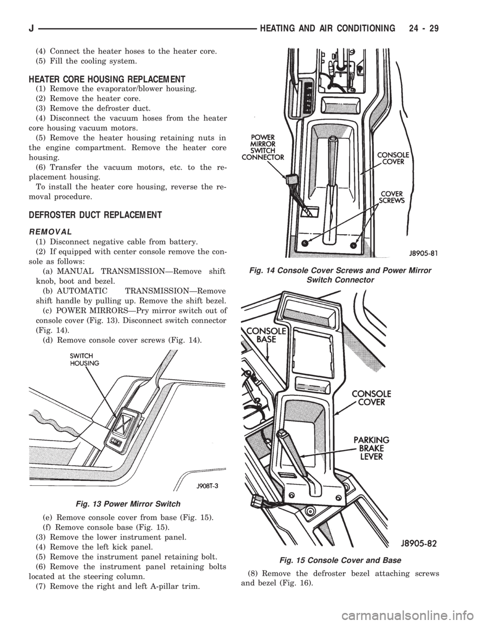
(c) POWER MIRRORSÐPry mirror switch out of
console cover (Fig. 13). Disconnect switch connector
(Fig. 14).
(d) Remove console cover screws (Fig. 14).
(e) Remove console cover from base (Fig. 15).
(f) Remove console base (Fig. 15).
(3) Remove the lower instrument panel.
(4) Remove the left kick panel.
(5) Remove the instrument panel retaining bolt.
(6) Remove the instrument panel retaining bolts
located at the steering column.
(7) Remove the right and left A-pillar trim.(8) Remove the defroster bezel attaching screws
and bezel (Fig. 16).
Fig. 13 Power Mirror Switch
Fig. 14 Console Cover Screws and Power Mirror
Switch Connector
Fig. 15 Console Cover and Base
JHEATING AND AIR CONDITIONING 24 - 29
Page 1693 of 1784
(9) Remove the instrument panel retaining screws.
(10) Lower the steering column.
(11) Pull the instrument panel, approximately 3
inches, away from the dash panel.
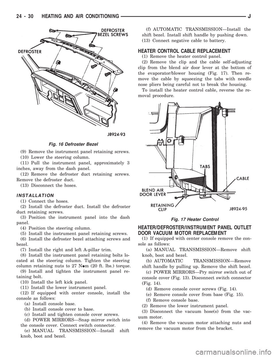
(12) Remove the defroster duct retaining screws.
Remove the defroster duct.
(13) Disconnect the hoses.
INSTALLATION
(1) Connect the hoses.
(2) Install the defroster duct. Install the defroster
duct retaining screws.
(3) Position the instrument panel into the dash
panel.
(4) Position the steering column.
(5) Install the instrument panel retaining screws.
(6) Install the defroster bezel attaching screws and
bezel.
(7) Install the right and left A-pillar trim.
(8) Install the instrument panel retaining bolts lo-
cated at the steering column. Tighten the steering
column retaining nuts to 27 NIm (20 ft. lbs.) torque.
(9) Install and tighten the instrument panel re-
taining bolt.
(10) Install the left kick panel.
(11) Install the lower instrument panel.
(12) If equipped with center console, install the
console as follows:
(a) Install console base.
(b) Install console cover to base.
(c) Install and tighten console cover screws.
(d) POWER MIRRORSÐSnap mirror switch into
the console cover. Connect switch connector.
(e) MANUAL TRANSMISSIONÐInstall shift
knob, boot and bezel.(f) AUTOMATIC TRANSMISSIONÐInstall the
shift bezel. Install shift handle by pushing down.
(13) Connect negative cable to battery.
HEATER CONTROL CABLE REPLACEMENT
(1) Remove the heater control panel.
(2) Remove the clip and the cable self-adjusting
clip from the blend air door lever at the bottom of
the evaporator/blower housing (Fig. 17). Then re-
move the cable by squeezing the tabs with needle
nose pliers being careful not to break the housing.
To install the heater control cable, reverse the re-
moval procedure.
HEATER/DEFROSTER/INSTRUMENT PANEL OUTLET
DOOR VACUUM MOTOR REPLACEMENT
(1) If equipped with center console remove the con-
sole as follows:
(a) MANUAL TRANSMISSIONÐRemove shift
knob, boot and bezel.
(b) AUTOMATIC TRANSMISSIONÐRemove
shift handle by pulling up. Remove the shift bezel.
(c) POWER MIRRORSÐPry mirror switch out of
console cover (Fig. 13). Disconnect switch connector
(Fig. 14).
(d) Remove console cover screws (Fig. 14).
(e) Remove console cover from base (Fig. 15).
(f) Remove console base.
(2) Remove the lower instrument panel.
(3) Disconnect the vacuum hose(s) from the vac-
uum motor.
(4) Remove the vacuum motor attaching nuts and
remove the vacuum motor from the bracket.
Fig. 16 Defroster Bezel
Fig. 17 Heater Control
24 - 30 HEATING AND AIR CONDITIONINGJ
Page 1696 of 1784
EVAPORATOR/BLOWER HOUSING
REMOVAL
(1) Disconnect negative cable from battery.
(2) Discharge the A/C system as described in this
section and disconnect the A/C hoses from the expan-
sion valve.
(3) Disconnect the blower motor wires and the vent
tube.
(4) If equipped with center console remove the con-
sole as follows:
(a) MANUAL TRANSMISSIONÐRemove shift
knob, boot and bezel.
(b) AUTOMATIC TRANSMISSIONÐRemove
shift handle by pulling up. Remove the shift bezel.
(c) POWER MIRRORSÐPry mirror switch out of
console cover (Fig. 13) and disconnect switch con-
nector (Fig. 14).
(d) Remove console cover screws (Fig. 14).
(e) Remove console cover from base (Fig. 15).
(f) Remove console base.
(5) Remove the lower instrument panel.
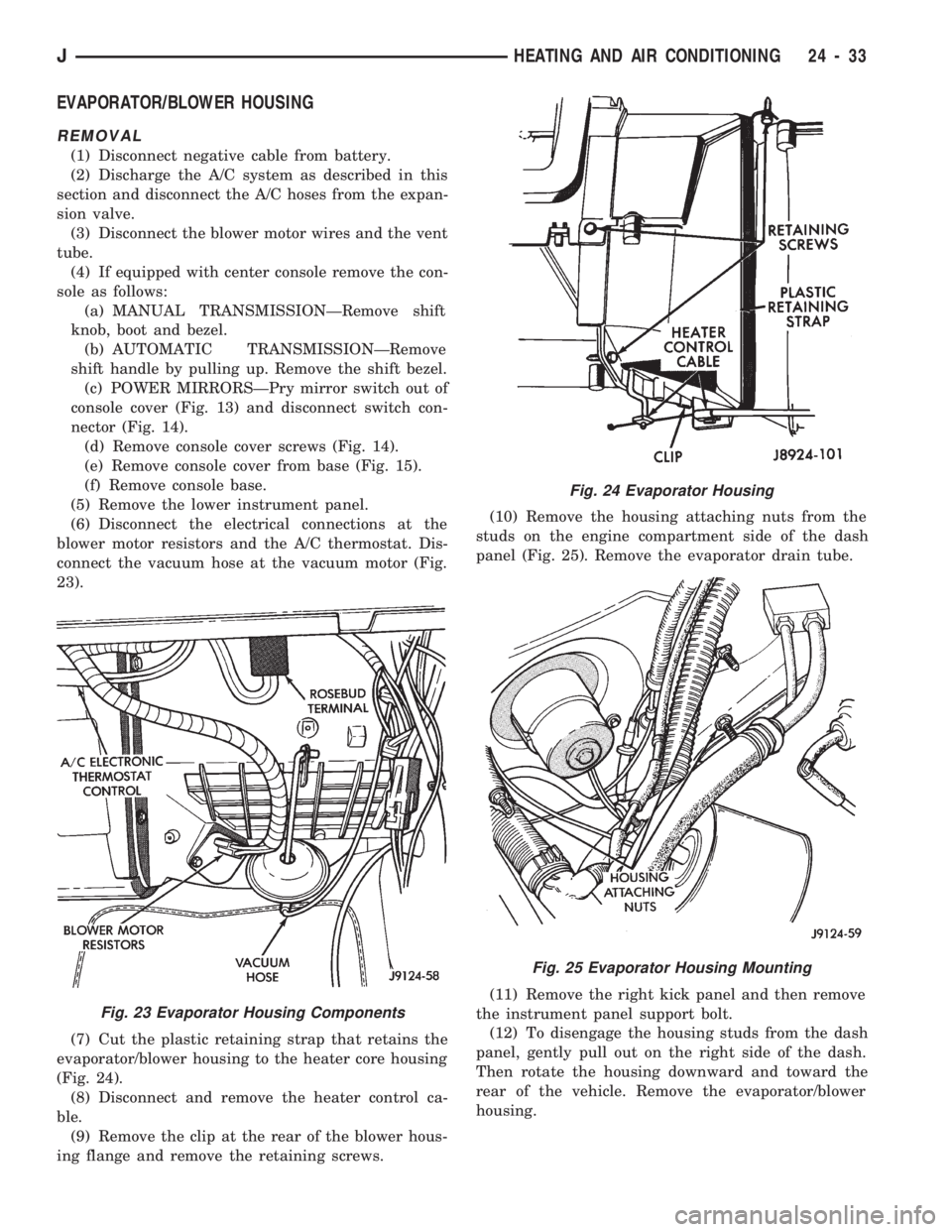
(6) Disconnect the electrical connections at the
blower motor resistors and the A/C thermostat. Dis-
connect the vacuum hose at the vacuum motor (Fig.
23).
(7) Cut the plastic retaining strap that retains the
evaporator/blower housing to the heater core housing
(Fig. 24).
(8) Disconnect and remove the heater control ca-
ble.
(9) Remove the clip at the rear of the blower hous-
ing flange and remove the retaining screws.(10) Remove the housing attaching nuts from the
studs on the engine compartment side of the dash
panel (Fig. 25). Remove the evaporator drain tube.
(11) Remove the right kick panel and then remove
the instrument panel support bolt.
(12) To disengage the housing studs from the dash
panel, gently pull out on the right side of the dash.
Then rotate the housing downward and toward the
rear of the vehicle. Remove the evaporator/blower
housing.
Fig. 23 Evaporator Housing Components
Fig. 24 Evaporator Housing
Fig. 25 Evaporator Housing Mounting
JHEATING AND AIR CONDITIONING 24 - 33
Page 1698 of 1784
(5) Install the evaporator/blower housing.
(6) Add 30 ml (1 fluid oz.) of refrigerant oil to the
air conditioning system if the evaporator was re-
placed.
EXPANSION (H) VALVE
REMOVAL
(1) Discharge the A/C system.
(2) Remove the coolant bottle and bracket.
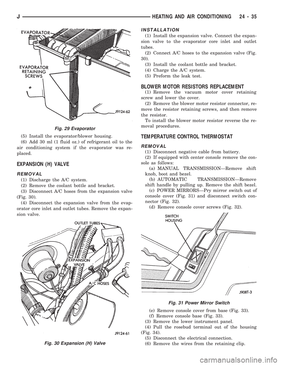
(3) Disconnect A/C hoses from the expansion valve
(Fig. 30).
(4) Disconnect the expansion valve from the evap-
orator core inlet and outlet tubes. Remove the expan-
sion valve.
INSTALLATION
(1) Install the expansion valve. Connect the expan-
sion valve to the evaporator core inlet and outlet
tubes.
(2) Connect A/C hoses to the expansion valve (Fig.
30).
(3) Install the coolant bottle and bracket.
(4) Charge the A/C system.
(5) Preform the leak test.
BLOWER MOTOR RESISTORS REPLACEMENT
(1) Remove the vacuum motor cover retaining
screw and lower the cover.
(2) Remove the blower motor resistor connector, re-
move the resistor retaining screws, and then remove
the resistor.
To install the blower motor resistor reverse the re-
moval procedures.
TEMPERATURE CONTROL THERMOSTAT
REMOVAL
(1) Disconnect negative cable from battery.
(2) If equipped with center console remove the con-
sole as follows:
(a) MANUAL TRANSMISSIONÐRemove shift
knob, boot and bezel.
(b) AUTOMATIC TRANSMISSIONÐRemove
shift handle by pulling up. Remove the shift bezel.
(c) POWER MIRRORSÐPry mirror switch out of
console cover (Fig. 31) and disconnect switch con-
nector (Fig. 32).
(d) Remove console cover screws (Fig. 32).
(e) Remove console cover from base (Fig. 33).
(f) Remove console base (Fig. 33).
(3) Remove the lower instrument panel.
(4) Pull the rosebud terminal out of the housing
(Fig. 34).
(5) Disconnect the electrical connection.
(6) Remove the wires from the retaining clip.
Fig. 29 Evaporator
Fig. 30 Expansion (H) Valve
Fig. 31 Power Mirror Switch
JHEATING AND AIR CONDITIONING 24 - 35