1994 JEEP CHEROKEE stop start
[x] Cancel search: stop startPage 111 of 1784
ing the IAC motor pintle in and out of the air control
passage. The IAC motor is positioned when the igni-
tion key is turned to the On position.
A (factory adjusted) set screw is used to mechani-
cally limit the position of the throttle body throttle
plate.Never attempt to adjust the engine idle
speed using this screw.All idle speed functions are
controlled by the PCM.
IGNITION COILÐPCM OUTPUT
System voltage is supplied to the ignition coil pos-
itive terminal. The powertrain control module (PCM)
operates the ignition coil.Base (initial) ignition
timing is not adjustable.The PCM adjusts ignition
timing to meet changing engine operating conditions.
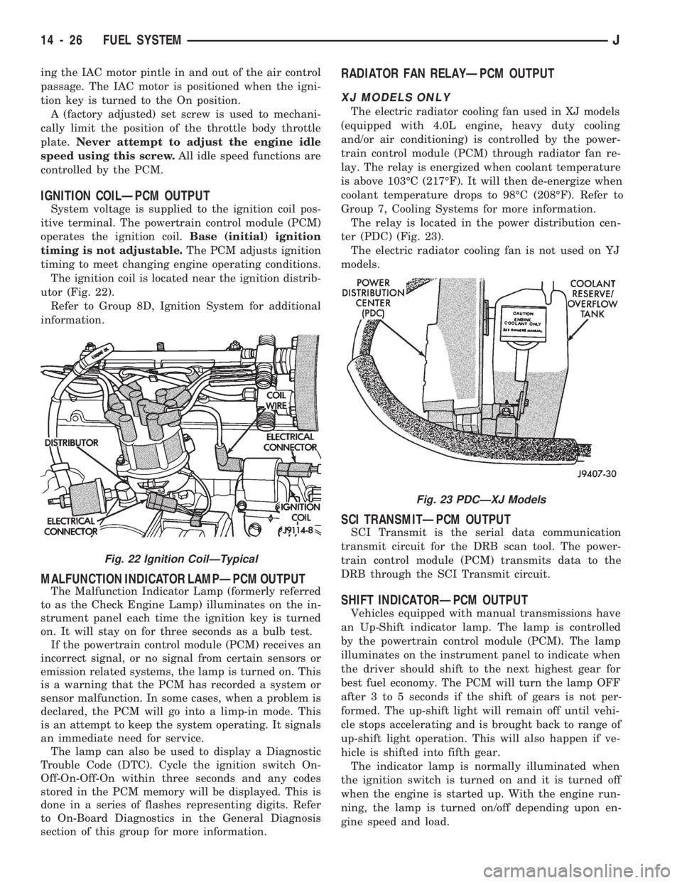
The ignition coil is located near the ignition distrib-
utor (Fig. 22).
Refer to Group 8D, Ignition System for additional
information.
MALFUNCTION INDICATOR LAMPÐPCM OUTPUT
The Malfunction Indicator Lamp (formerly referred
to as the Check Engine Lamp) illuminates on the in-
strument panel each time the ignition key is turned
on. It will stay on for three seconds as a bulb test.
If the powertrain control module (PCM) receives an
incorrect signal, or no signal from certain sensors or
emission related systems, the lamp is turned on. This
is a warning that the PCM has recorded a system or
sensor malfunction. In some cases, when a problem is
declared, the PCM will go into a limp-in mode. This
is an attempt to keep the system operating. It signals
an immediate need for service.
The lamp can also be used to display a Diagnostic
Trouble Code (DTC). Cycle the ignition switch On-
Off-On-Off-On within three seconds and any codes
stored in the PCM memory will be displayed. This is
done in a series of flashes representing digits. Refer
to On-Board Diagnostics in the General Diagnosis
section of this group for more information.
RADIATOR FAN RELAYÐPCM OUTPUT
XJ MODELS ONLY
The electric radiator cooling fan used in XJ models
(equipped with 4.0L engine, heavy duty cooling
and/or air conditioning) is controlled by the power-
train control module (PCM) through radiator fan re-
lay. The relay is energized when coolant temperature
is above 103ÉC (217ÉF). It will then de-energize when
coolant temperature drops to 98ÉC (208ÉF). Refer to
Group 7, Cooling Systems for more information.
The relay is located in the power distribution cen-
ter (PDC) (Fig. 23).
The electric radiator cooling fan is not used on YJ
models.
SCI TRANSMITÐPCM OUTPUT
SCI Transmit is the serial data communication
transmit circuit for the DRB scan tool. The power-
train control module (PCM) transmits data to the
DRB through the SCI Transmit circuit.
SHIFT INDICATORÐPCM OUTPUT
Vehicles equipped with manual transmissions have
an Up-Shift indicator lamp. The lamp is controlled
by the powertrain control module (PCM). The lamp
illuminates on the instrument panel to indicate when
the driver should shift to the next highest gear for
best fuel economy. The PCM will turn the lamp OFF
after 3 to 5 seconds if the shift of gears is not per-
formed. The up-shift light will remain off until vehi-
cle stops accelerating and is brought back to range of
up-shift light operation. This will also happen if ve-
hicle is shifted into fifth gear.
The indicator lamp is normally illuminated when
the ignition switch is turned on and it is turned off
when the engine is started up. With the engine run-
ning, the lamp is turned on/off depending upon en-
gine speed and load.
Fig. 23 PDCÐXJ Models
Fig. 22 Ignition CoilÐTypical
14 - 26 FUEL SYSTEMJ
Page 151 of 1784

scan tool will be necessary to determine which ABS
component has malfunctioned.
ABS Light Illuminates During Brake Stop
A system fault such as loss of speed sensor signal
or solenoid failure, will cause the amber warning
light to illuminate. The most effective procedure here
is to check for obvious damage first. Then check the
electronic components with the DRB II scan tool.
BRAKE WARNING LIGHT DISPLAY
The red brake warning light and the ABS light op-
erate independently. If the red light remains on after
startup or illuminates during a brake stop, refer to
the standard brake system diagnosis section. Either
the parking brakes are applied, or a wheel brake
malfunction has occurred.
ECU DIAGNOSIS
The ECU controls all phases of antilock system op-
eration. It also differentiates between normal and an-
tilock mode braking.
The ECU monitors and processes the signals gen-
erated from all of the system sensors at all times.
The ECU program includes a self check routine
that tests each of the system components. The self
check occurs during both phases of the initialization
program. A failure of the self check program will
cause the immediate illumination of the amber warn-
ing light. The light will also illuminate if a solenoid
or other system component fails during the dynamic
phase of initialization.
If a system malfunction should occur, do not imme-
diately replace the ECU. A blown system fuse, bad
chassis ground, or loss of feed voltage will each cause
a system malfunction similar to an ECU failure.
Never replace the ECU unless diagnosis with the
DRB II scan tool indicates this is necessary.
HCU DIAGNOSIS
The HCU pump and motor and solenoid valve body
are serviced only as an assembly. The HCU assembly
should not be replaced unless a fault has actually
been confirmed. Verify fault conditions with the DRB
II scan tool before proceeding with repair.
ABS SYSTEM WIRING AND ELECTRICAL CIRCUITS
Location of the ABS fuse (in the fuse panel) is
shown in Figure 1. The engine compartment harness
routing for the ABS components is shown in Figure 2.
ABS FAULT DIAGNOSIS
The fault diagnosis chart provides additional infor-
mation on potential ABS system faults. Use the
chart as a guide when diagnosing a system problem.
Fig. 1 ABS Fuse Location
5 - 4 BRAKESJ
Page 155 of 1784
(2) If red warning light is illuminated, or if neither
warning light is illuminated, make several stops and
note pedal action and brake response.
(3) Check brake pedal response with transmission
in Neutral and engine running. Pedal should remain
firm under steady foot pressure. If pedal falls away,
problem is either in vacuum booster or master cylin-
der.
(4) During road test, make normal and firm brake
stops in 25-40 mph range. Note faulty brake opera-
tion such as pull, grab, drag, noise, fade, pedal pul-
sation, etc.
(5) Inspect suspect brake components and refer to
problem diagnosis information for causes of various
brake conditions.
COMPONENT INSPECTION
Fluid leak points and dragging brake units can
usually be located without removing any compo-
nents. The area around a leak point will be wet with
fluid. The components at a dragging brake unit
(wheel, tire, rotor) will be quite warm or hot to the
touch.
Other brake problem conditions will require compo-
nent removal for proper inspection. Raise the vehicle
and remove the necessary wheels for better visual ac-
cess.
During component inspection, pay particular atten-
tion to heavily rusted/corroded brake components
(e.g. rotors, caliper pistons, brake return/holddown
springs, support plates, etc.).
Heavy accumulations of rust may be covering se-
vere damage to a brake component. It is wise to re-
move surface rust in order to accurately determine
the depth of rust penetration and damage. Light sur-
face rust is fairly normal and not a major concern (as
long as it is removed). However, heavy rust buildup,
especially on high mileage vehicles may cover struc-
tural damage to such important components as
brakelines, rotors, support plates, and brake boosters.
Refer to the wheel brake service procedures in this
group for more information.
DIAGNOSING SERVICE BRAKE PROBLEMS
BRAKE WARNING LIGHT OPERATION
The red brake warning light will illuminate under
the following conditions:
²for 2-3 seconds at startup as part of normal bulb
check
²parking brakes applied
²low pedal caused by malfunction in front/rear
brake hydraulic circuit (differential switch valve ac-
tuated)
If the red light remains on after startup, first ver-
ify that the parking brakes are fully released. Then
check pedal action and fluid level. A red light indi-
cates that the valve in the differential pressureswitch has been actuated. If a problem is confirmed,
inspect the hydraulic system and wheel brake compo-
nents.
On models with ABS brakes, the amber warning
light only illuminates when an ABS component has
malfunctioned. The ABS light operates indepen-
dently of the red warning light. Refer to the antilock
brake section for more detailed diagnosis informa-
tion.
PEDAL FALLS AWAY
A brake pedal that falls away under steady foot
pressure is generally the result of a system leak. The
leak point could be at a brakeline, fitting, hose,
wheel cylinder, or caliper. Internal leakage in the
master cylinder caused by worn or damaged piston
cups, may also be the problem cause.
If leakage is severe, fluid will be evident at or
around the leaking component. However internal
leakage in the master cylinder will not be physically
evident. Refer to the cylinder test procedure in this
section.
LOW PEDAL
If a low pedal is experienced, pump the pedal sev-
eral times. If the pedal comes back up, worn lining
and worn rotors or drums are the most likely causes.
However, if the pedal remains low and/or the warn-
ing light illuminates, the problem is in the master
cylinder, wheel cylinders, or calipers.
A decrease in master cylinder fluid level may only
be the result of normal lining wear. Fluid level will
decrease as lining wear occurs. It is a result of the
outward movement of caliper and wheel cylinder pis-
tons to compensate for normal wear.
SPONGY PEDAL
A spongy pedal is most often caused by air in the
system. However, thin drums or substandard brake
lines and hoses will also cause a condition similar to
a spongy pedal. The proper course of action is to
bleed the system, or replace thin drums and suspect
quality brake lines and hoses.
HARD PEDAL OR HIGH PEDAL EFFORT
A hard pedal or high pedal effort may be due to
lining that is water soaked, contaminated, glazed, or
badly worn. The power booster or check valve could
also be faulty. Test the booster and valve as de-
scribed in this section.
BRAKE DRAG
Brake drag occurs when the lining is in constant
contact with the rotor or drum. Drag can occur at
one wheel, all wheels, fronts only, or rears only. It is
a product of incomplete brakeshoe release. Drag can
be minor or severe enough to overheat the linings,
rotors and drums.
5 - 8 BRAKESJ
Page 158 of 1784
assembled, they will not function. In addition, since
the adjuster mechanism only works during reverse
stops, it is important that complete stops be made.
The adjuster mechanism does not operate when roll-
ing stops are made in reverse. The vehicle must be
brought to a complete halt before the adjuster lever
will turn the adjuster screw.
A condition where the parking brakes do not hold,
will most probably be due to a wheel brake compo-
nent.
Items to look for when diagnosing a parking brake
problem, are:
²rear brakeshoe wear
²rear brakedrum wear
²brakedrums machined beyond allowable diameter
(oversize)
²parking brake front cable not secured to lever
²parking brake rear cable seized
²parking brake strut reversed
²parking brake strut not seated in both shoes
²parking brake lever not seated in secondary shoe
²parking brake lever or brakeshoe bind on support
plate
²brakeshoes reversed
²adjuster screws seized
²adjuster screws reversed
²holddown or return springs misassembled or lack
tension
²wheel cylinder pistons seized
Brake drums that are machined oversize are diffi-
cult to identify. If oversize drums are suspected, the
diameter of the braking surface will have to be
checked with an accurate drum gauge. Oversize
drums will cause low brake pedal and lack of park-
ing brake holding ability.
Improper parking brake strut and lever installa-
tion will result in unsatisfactory parking brake oper-
ation. Intermixing the adjuster screws will cause
drag, bind and pull along with poor parking brake
operation.
Parking brake adjustment and parts replacement
procedures are described in the Parking Brake sec-
tion.
MASTER CYLINDER/POWER BOOSTER TEST
(1) Start engine and check booster vacuum hose
connections. Hissing noise indicates vacuum leak.
Correct any vacuum leak before proceeding.
(2) Stop engine and shift transmission into Neu-
tral.
(3) Pump brake pedal until all vacuum reserve in
booster is depleted.
(4) Press and hold brake pedal under light foot
pressure.
(a) If pedal holds firm, proceed to step (5).
(b) If pedal does not hold firm and falls away,
master cylinder is faulty (internal leakage). Over-
haul or replace cylinder.(5) Start engine and note pedal action.
(a) If pedal falls away slightly under light foot
pressure then holds firm, proceed to step (6).
(b) If no pedal action is discernible, power
booster or vacuum check valve is faulty. Install
known good check valve and repeat steps (2)
through (5).
(6) Rebuild booster vacuum reserve as follows: Re-
lease brake pedal. Increase engine speed to 1500
rpm, close throttle and immediately turn off ignition.
(7) Wait a minimum of 90 seconds and try brake
action again. Booster should provide two or more
vacuum assisted pedal applications. If vacuum assist
is not provided, perform booster and check valve vac-
uum tests.
POWER BOOSTER CHECK VALVE TEST
(1) Disconnect vacuum hose from check valve.
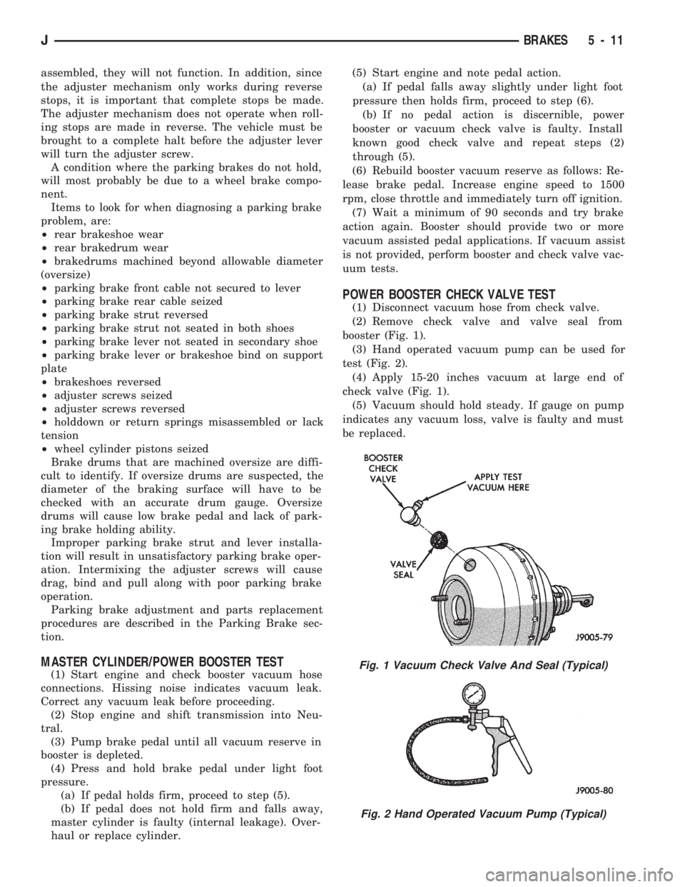
(2) Remove check valve and valve seal from
booster (Fig. 1).
(3) Hand operated vacuum pump can be used for
test (Fig. 2).
(4) Apply 15-20 inches vacuum at large end of
check valve (Fig. 1).
(5) Vacuum should hold steady. If gauge on pump
indicates any vacuum loss, valve is faulty and must
be replaced.
Fig. 1 Vacuum Check Valve And Seal (Typical)
Fig. 2 Hand Operated Vacuum Pump (Typical)
JBRAKES 5 - 11
Page 159 of 1784
POWER BOOSTER VACUUM TEST
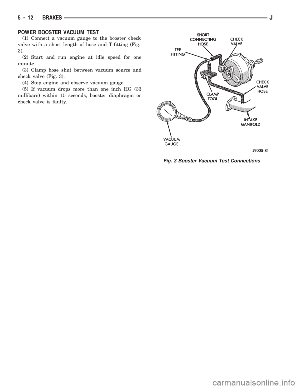
(1) Connect a vacuum gauge to the booster check
valve with a short length of hose and T-fitting (Fig.
3).
(2) Start and run engine at idle speed for one
minute.
(3) Clamp hose shut between vacuum source and
check valve (Fig. 3).
(4) Stop engine and observe vacuum gauge.
(5) If vacuum drops more than one inch HG (33
millibars) within 15 seconds, booster diaphragm or
check valve is faulty.
Fig. 3 Booster Vacuum Test Connections
5 - 12 BRAKESJ
Page 189 of 1784
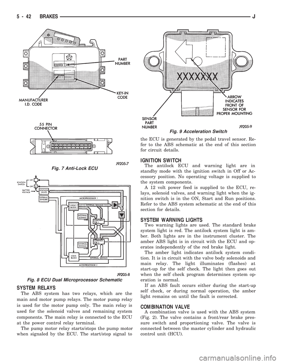
SYSTEM RELAYS
The ABS system has two relays, which are the
main and motor pump relays. The motor pump relay
is used for the motor pump only. The main relay is
used for the solenoid valves and remaining system
components. The main relay is connected to the ECU
at the power control relay terminal.
The pump motor relay starts/stops the pump motor
when signaled by the ECU. The start/stop signal tothe ECU is generated by the pedal travel sensor. Re-
fer to the ABS schematic at the end of this section
for circuit details.
IGNITION SWITCH
The antilock ECU and warning light are in
standby mode with the ignition switch in Off or Ac-
cessory position. No operating voltage is supplied to
the system components.
A 12 volt power feed is supplied to the ECU, re-
lays, solenoid valves, and warning light when the ig-
nition switch is in the ON, Start and Run positions.
Refer to the ABS system schematic at the end of this
section for details.
SYSTEM WARNING LIGHTS
Two warning lights are used. The standard brake
system light is red. The antilock system light is am-
ber. Both lights are in the instrument cluster. The
amber ABS light is in circuit with the ECU and op-
erates independently of the red brake light.
The amber light indicates antilock system condi-
tion. It is in circuit with the valve body solenoids and
main relay. The light illuminates (flashes) at
start-up for the self check. The light then goes out
when the self check program determines system op-
eration is normal.
If an ABS fault occurs either during the start-up
self check, or during normal operation, the amber
light remains on until the fault is corrected.
COMBINATION VALVE
A combination valve is used with the ABS system
(Fig. 2). The valve contains a front/rear brake pres-
sure switch and proportioning valve. The valve is
connected between the master cylinder and hydraulic
control unit (HCU).
Fig. 7 Anti-Lock ECU
Fig. 8 ECU Dual Microprocessor Schematic
Fig. 9 Acceleration Switch
5 - 42 BRAKESJ
Page 251 of 1784
REVERSE FLUSHING ENGINE
Drain the cooling system. Remove the thermostat
housing and thermostat. Install the thermostat hous-
ing. Disconnect the radiator upper hose from the ra-
diator and attach the flushing gun to the hose.
Disconnect the radiator lower hose from the water
pump. Attach a lead away hose to the water pump
inlet fitting.
CAUTION: On XJ models, be sure that the heater
control valve is closed (heat off). This is done to
prevent coolant flow with scale and other deposits
from entering the heater core.
Connect the water supply hose and air supply hose
to the flushing gun. Allow the engine to fill with wa-
ter. When the engine is filled, apply air in short
blasts, allowing the system to fill between air blasts.
Continue until clean water flows through the lead
away hose. For more information, refer to operating
instructions supplied with flushing equipment.
Remove the lead away hose, flushing gun, water
supply hose and air supply hose. Remove the thermo-
stat housing and install thermostat. Install the ther-
mostat housing with a replacement gasket. Refer to
Thermostat Replacement. Connect the radiator hoses.
Refill the cooling system with the correct antifreeze/
water mixture.
CHEMICAL CLEANING
In some instances, use a radiator cleaner (Mopar
Radiator Kleen or equivalent) before flushing. This
will soften scale and other deposits and aid the flush-
ing operation.
CAUTION: Be sure instructions on the container are
followed.
TESTING COOLING SYSTEM FOR LEAKS
ULTRAVIOLET LIGHT METHOD
All JeepŸ models have a leak detection additive
added to the cooling system before they leave the fac-
tory. The additive is highly visible under ultraviolet
light (black light). If the factory original coolant has
been drained, pour one ounce of additive into the
cooling system. The additive is available through the
part's department. Place the heater control unit in
HEAT position. Start and operate the engine until
the radiator upper hose is warm to the touch. Aim
the black light (tool 7138 or an equivalent), at the
components to be checked. If leaks are present, the
black light will cause the additive to glow a bright
green color.
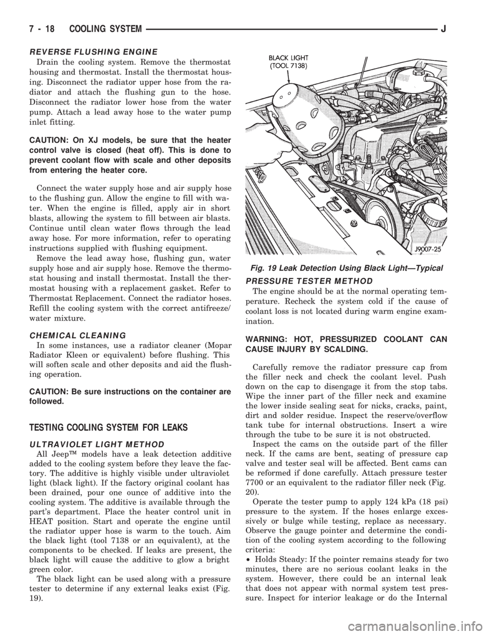
The black light can be used along with a pressure
tester to determine if any external leaks exist (Fig.
19).
PRESSURE TESTER METHOD
The engine should be at the normal operating tem-
perature. Recheck the system cold if the cause of
coolant loss is not located during warm engine exam-
ination.
WARNING: HOT, PRESSURIZED COOLANT CAN
CAUSE INJURY BY SCALDING.
Carefully remove the radiator pressure cap from
the filler neck and check the coolant level. Push
down on the cap to disengage it from the stop tabs.
Wipe the inner part of the filler neck and examine
the lower inside sealing seat for nicks, cracks, paint,
dirt and solder residue. Inspect the reserve/overflow
tank tube for internal obstructions. Insert a wire
through the tube to be sure it is not obstructed.
Inspect the cams on the outside part of the filler
neck. If the cams are bent, seating of pressure cap
valve and tester seal will be affected. Bent cams can
be reformed if done carefully. Attach pressure tester
7700 or an equivalent to the radiator filler neck (Fig.
20).
Operate the tester pump to apply 124 kPa (18 psi)
pressure to the system. If the hoses enlarge exces-
sively or bulge while testing, replace as necessary.
Observe the gauge pointer and determine the condi-
tion of the cooling system according to the following
criteria:
²Holds Steady: If the pointer remains steady for two
minutes, there are no serious coolant leaks in the
system. However, there could be an internal leak
that does not appear with normal system test pres-
sure. Inspect for interior leakage or do the Internal
Fig. 19 Leak Detection Using Black LightÐTypical
7 - 18 COOLING SYSTEMJ
Page 252 of 1784

Leakage Test. Do this if it is certain that coolant is
being lost and no leaks can be detected.
²Drops Slowly: Shows a small leak or seepage is oc-
curring. Examine all connections for seepage or
slight leakage with a flashlight. Inspect the radiator,
hoses, gasket edges and heater. Seal any small leak
holes with a Sealer Lubricant or equivalent. Repair
leak holes and reinspect the system with pressure
applied.
²Drops Quickly: Shows that a serious leakage is oc-
curring. Examine the system for serious external
leakage. If no leaks are visible, inspect for internal
leakage. Large radiator leak holes should be repaired
by a reputable radiator repair shop.
INTERNAL LEAKAGE INSPECTION
Remove the oil pan drain plug and drain a small
amount of engine oil. Coolant, being heavier will
drain first, or operate engine to churn oil, then ex-
amine dipstick for water globules. Inspect the trans-
mission dipstick for water globules. Inspect the
transmission fluid cooler for leakage. Operate the en-
gine without the pressure cap on the radiator until
thermostat opens.
Attach a Pressure Tester to the filler neck. If pres-
sure builds up quickly, a leak exists as result of a
faulty cylinder head gasket or crack in the engine.
Repair as necessary.
WARNING: DO NOT ALLOW PRESSURE TO EX-
CEED 124 KPA (18 PSI). TURN THE ENGINE OFF.
TO RELEASE THE PRESSURE, ROCK THE TESTER
FROM SIDE TO SIDE. WHEN REMOVING THE
TESTER, DO NOT TURN THE TESTER MORE THAN
1/2 TURN IF THE SYSTEM IS UNDER PRESSURE.
If there is no immediate pressure increase, pump
the Pressure Tester until the indicated pressure is
within the system range. Vibration of the gauge
pointer indicates compression or combustion leakage
into the cooling system.WARNING: DO NOT DISCONNECT THE SPARK
PLUG WIRES WHILE THE ENGINE IS OPERATING.
CAUTION: Do not operate the engine with a spark
plug shorted for more than a minute. The catalytic
converter may be damaged.
Isolate the compression leak by shorting each
spark plug to the cylinder block. The gauge pointer
should stop or decrease vibration when spark plug
for leaking cylinder is shorted. This happens because
of the absence of combustion pressure.
COMBUSTION LEAKAGE TEST (WITHOUT
PRESSURE TESTER)
DO NOT WASTE reusable coolant. If the solution
is clean, drain the coolant into a clean container for
reuse.
WARNING: DO NOT REMOVE THE CYLINDER
BLOCK DRAIN PLUGS OR LOOSEN THE RADIATOR
DRAINCOCK WITH THE SYSTEM HOT AND UNDER
PRESSURE. SERIOUS BURNS FROM COOLANT
CAN OCCUR.
Drain sufficient coolant to allow for thermostat re-
moval. Refer to Thermostat Replacement. Disconnect
the water pump drive belt.
Disconnect the upper radiator hose from the ther-
mostat housing. Remove the housing and thermostat.
Install the thermostat housing.
Add coolant to the radiator to bring the level to
within 6.3 mm (1/4 in) of the top of the thermostat
housing.
CAUTION: Avoid overheating. Do not operate the
engine for an excessive period of time. Open the
draincock immediately after the test to eliminate
boil over of coolant.
Start the engine and accelerate rapidly three times
(to approximately 3000 rpm) while observing the
coolant. If internal engine combustion gases are leak-
ing into the cooling system, bubbles will appear in
the coolant. If bubbles do not appear, there is no in-
ternal combustion gas leakage.
COOLANT RESERVE/OVERFLOW SYSTEM
The system works along with the radiator pressure
cap. This is done by using thermal expansion and
contraction of the coolant to keep the coolant free of
trapped air. It provides:
²A volume for coolant expansion and contraction.
²A convenient and safe method for checking/adjust-
ing coolant level at atmospheric pressure. This is
done without removing the radiator pressure cap.
²Some reserve coolant to cover minor leaks and
evaporation or boiling losses.
Fig. 20 Pressurizing SystemÐTypical
JCOOLING SYSTEM 7 - 19