1994 JEEP CHEROKEE warning
[x] Cancel search: warningPage 1091 of 1784
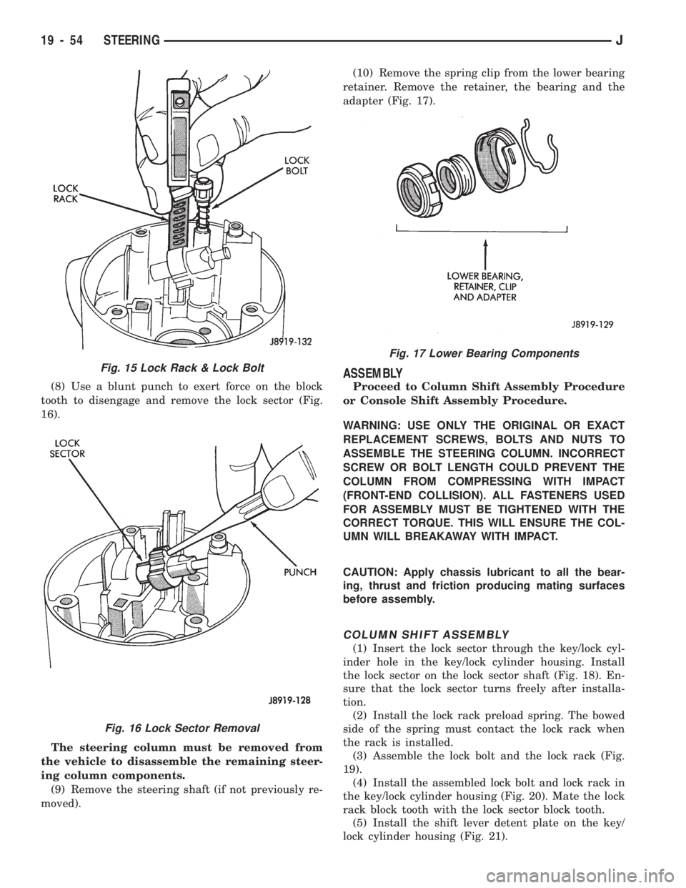
(8) Use a blunt punch to exert force on the block
tooth to disengage and remove the lock sector (Fig.
16).
The steering column must be removed from
the vehicle to disassemble the remaining steer-
ing column components.
(9) Remove the steering shaft (if not previously re-
moved).(10) Remove the spring clip from the lower bearing
retainer. Remove the retainer, the bearing and the
adapter (Fig. 17).
ASSEMBLY
Proceed to Column Shift Assembly Procedure
or Console Shift Assembly Procedure.
WARNING: USE ONLY THE ORIGINAL OR EXACT
REPLACEMENT SCREWS, BOLTS AND NUTS TO
ASSEMBLE THE STEERING COLUMN. INCORRECT
SCREW OR BOLT LENGTH COULD PREVENT THE
COLUMN FROM COMPRESSING WITH IMPACT
(FRONT-END COLLISION). ALL FASTENERS USED
FOR ASSEMBLY MUST BE TIGHTENED WITH THE
CORRECT TORQUE. THIS WILL ENSURE THE COL-
UMN WILL BREAKAWAY WITH IMPACT.
CAUTION: Apply chassis lubricant to all the bear-
ing, thrust and friction producing mating surfaces
before assembly.
COLUMN SHIFT ASSEMBLY
(1) Insert the lock sector through the key/lock cyl-
inder hole in the key/lock cylinder housing. Install
the lock sector on the lock sector shaft (Fig. 18). En-
sure that the lock sector turns freely after installa-
tion.
(2) Install the lock rack preload spring. The bowed
side of the spring must contact the lock rack when
the rack is installed.
(3) Assemble the lock bolt and the lock rack (Fig.
19).
(4) Install the assembled lock bolt and lock rack in
the key/lock cylinder housing (Fig. 20). Mate the lock
rack block tooth with the lock sector block tooth.
(5) Install the shift lever detent plate on the key/
lock cylinder housing (Fig. 21).
Fig. 17 Lower Bearing Components
Fig. 15 Lock Rack & Lock Bolt
Fig. 16 Lock Sector Removal
19 - 54 STEERINGJ
Page 1094 of 1784
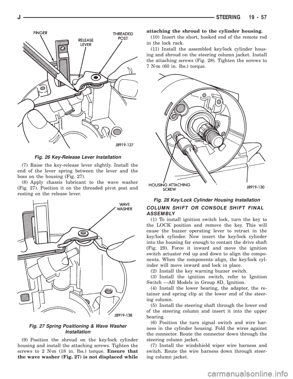
(7) Raise the key-release lever slightly. Install the
end of the lever spring between the lever and the
boss on the housing (Fig. 27).
(8) Apply chassis lubricant to the wave washer
(Fig. 27). Position it on the threaded pivot post and
resting on the release lever.
(9) Position the shroud on the key/lock cylinder
housing and install the attaching screws. Tighten the
screws to 2 Nzm (18 in. lbs.) torque.Ensure that
the wave washer (Fig. 27) is not displaced whileattaching the shroud to the cylinder housing.
(10) Insert the short, hooked end of the remote rod
in the lock rack.
(11) Install the assembled key/lock cylinder hous-
ing and shroud on the steering column jacket. Install
the attaching screws (Fig. 28). Tighten the screws to
7Nzm (60 in. lbs.) torque.
COLUMN SHIFT OR CONSOLE SHIFT FINAL
ASSEMBLY
(1) To install ignition switch lock, turn the key to
the LOCK position and remove the key. This will
cause the buzzer operating lever to retract in the
key/lock cylinder. Now insert the key/lock cylinder
into the housing far enough to contact the drive shaft
(Fig. 29). Force it inward and move the ignition
switch actuator rod up and down to align the compo-
nents. When the components align, the key/lock cyl-
inder will move inward and lock in place.
(2) Install the key warning buzzer switch.
(3) Install the ignition switch, refer to Ignition
Switch ÐAll Models in Group 8D, Ignition.
(4) Install the lower bearing, the adapter, the re-
tainer and spring clip at the lower end of the steer-
ing column.
(5) Install the steering shaft through the lower end
of the steering column and insert it into the upper
bearing.
(6) Position the turn signal switch and wire har-
ness in the cylinder housing. Fold the wires against
the connector. Route the connector down through the
steering column jacket.
(7) Install the windshield wiper wire harness and
switch. Route the wire harness down through steer-
ing column jacket.
Fig. 28 Key/Lock Cylinder Housing Installation
Fig. 26 Key-Release Lever Installation
Fig. 27 Spring Positioning & Wave Washer
Installation
JSTEERING 19 - 57
Page 1095 of 1784
(8) Align the turn signal switch in the housing and
secure the switch with the attaching screws. Tighten
the screws to 4 Nzm (35 in. lbs.) torque.
(9) Install the dimmer switch actuator arm.
Tighten the attaching screws to 4 Nzm (35 in. lbs.)
torque.
(10) If equipped, install the cruise control wire har-
ness. Install the turn signal stalk by pushing it
straight into the column.
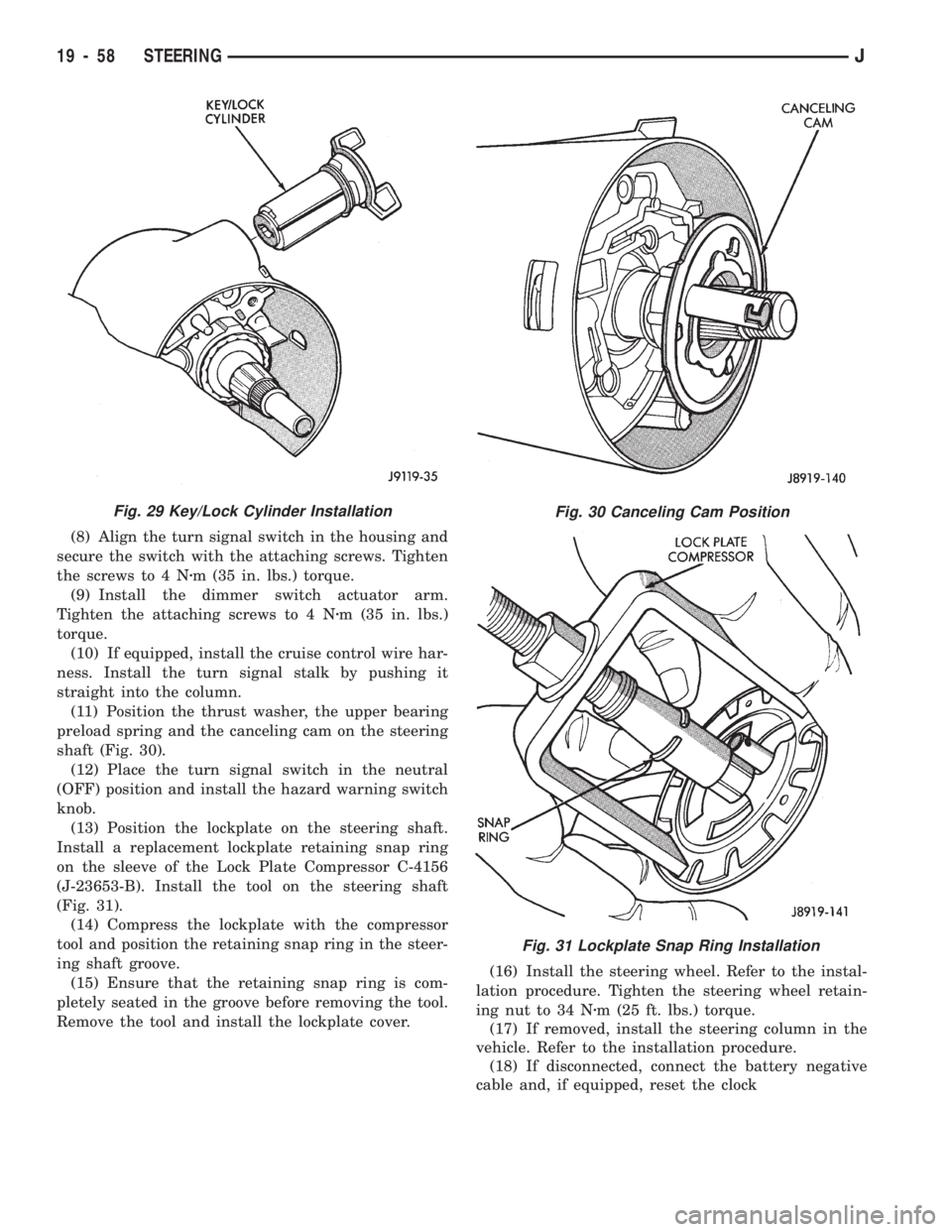
(11) Position the thrust washer, the upper bearing
preload spring and the canceling cam on the steering
shaft (Fig. 30).
(12) Place the turn signal switch in the neutral
(OFF) position and install the hazard warning switch
knob.
(13) Position the lockplate on the steering shaft.
Install a replacement lockplate retaining snap ring
on the sleeve of the Lock Plate Compressor C-4156
(J-23653-B). Install the tool on the steering shaft
(Fig. 31).
(14) Compress the lockplate with the compressor
tool and position the retaining snap ring in the steer-
ing shaft groove.
(15) Ensure that the retaining snap ring is com-
pletely seated in the groove before removing the tool.
Remove the tool and install the lockplate cover.(16) Install the steering wheel. Refer to the instal-
lation procedure. Tighten the steering wheel retain-
ing nut to 34 Nzm (25 ft. lbs.) torque.
(17) If removed, install the steering column in the
vehicle. Refer to the installation procedure.
(18) If disconnected, connect the battery negative
cable and, if equipped, reset the clock
Fig. 30 Canceling Cam Position
Fig. 31 Lockplate Snap Ring Installation
Fig. 29 Key/Lock Cylinder Installation
19 - 58 STEERINGJ
Page 1096 of 1784
TILT STEERING COLUMN
DISASSEMBLY
(1) Remove the steering column from the vehicle,
if necessary. Refer to the removal procedure.
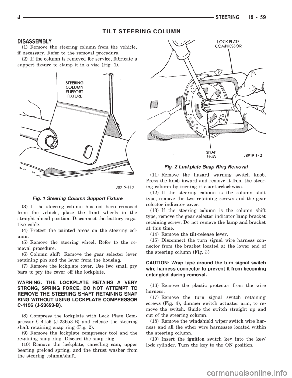
(2) If the column is removed for service, fabricate a
support fixture to clamp it in a vise (Fig. 1).
(3) If the steering column has not been removed
from the vehicle, place the front wheels in the
straight-ahead position. Disconnect the battery nega-
tive cable.
(4) Protect the painted areas on the steering col-
umn.
(5) Remove the steering wheel. Refer to the re-
moval procedure.
(6) Column shift: Remove the gear selector lever
retaining pin and the lever from the housing.
(7) Remove the lockplate cover. Use two small pry
bars to pry the cover off the lockplate.
WARNING: THE LOCKPLATE RETAINS A VERY
STRONG, SPRING FORCE. DO NOT ATTEMPT TO
REMOVE THE STEERING SHAFT RETAINING SNAP
RING WITHOUT USING LOCKPLATE COMPRESSOR
C-4156 (J-23653-B).
(8) Compress the lockplate with Lock Plate Com-
pressor C-4156 (J-23653-B) and release the steering
shaft retaining snap ring (Fig. 2).
(9) Remove the lockplate compressor tool and the
retaining snap ring. Discard the snap ring.
(10) Remove the lockplate, canceling cam, upper
bearing preload spring, and the thrust washer from
the steering column/shaft.(11) Remove the hazard warning switch knob.
Press the knob inward and remove it from the steer-
ing column by turning it counterclockwise.
(12) If the steering column is the column shift
type, remove the two retaining screws and the gear
selector indicator cover.
(13) If the steering column is the column shift
type, remove the gear selector indicator lamp bracket
retaining screw. Do not remove the lamp and bracket
at this time.
(14) Remove the tilt-release lever.
(15) Disconnect the turn signal wire harness con-
nector from the bracket located at the lower end of
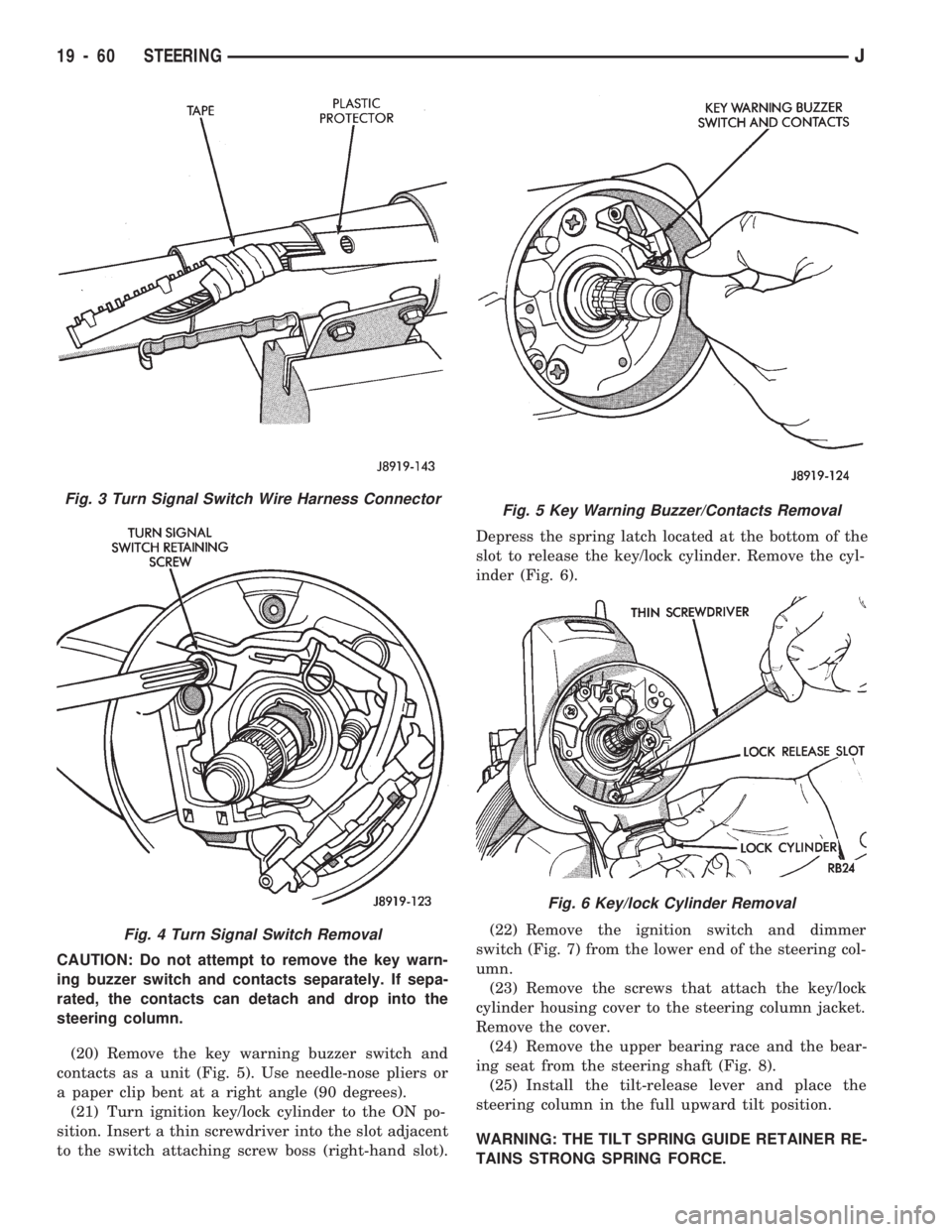
the steering column (Fig. 3).
CAUTION: Wrap tape around the turn signal switch
wire harness connector to prevent it from becoming
entangled during removal.
(16) Remove the plastic protector from the wire
harness.
(17) Remove the turn signal switch retaining
screws (Fig. 4), dimmer switch actuator arm, to re-
move the switch. Guide the switch straight up and
out of the steering column.
(18) Remove the windshield wiper switch wire har-
ness and all the other wire harnesses located within
the steering column.
(19) Insert the ignition switch key into the key/
lock cylinder. Turn the key to the ON position.
Fig. 1 Steering Column Support Fixture
Fig. 2 Lockplate Snap Ring Removal
JSTEERING 19 - 59
Page 1097 of 1784
CAUTION: Do not attempt to remove the key warn-
ing buzzer switch and contacts separately. If sepa-
rated, the contacts can detach and drop into the
steering column.
(20) Remove the key warning buzzer switch and
contacts as a unit (Fig. 5). Use needle-nose pliers or
a paper clip bent at a right angle (90 degrees).
(21) Turn ignition key/lock cylinder to the ON po-
sition. Insert a thin screwdriver into the slot adjacent
to the switch attaching screw boss (right-hand slot).Depress the spring latch located at the bottom of the
slot to release the key/lock cylinder. Remove the cyl-
inder (Fig. 6).
(22) Remove the ignition switch and dimmer
switch (Fig. 7) from the lower end of the steering col-
umn.
(23) Remove the screws that attach the key/lock
cylinder housing cover to the steering column jacket.
Remove the cover.
(24) Remove the upper bearing race and the bear-
ing seat from the steering shaft (Fig. 8).
(25) Install the tilt-release lever and place the
steering column in the full upward tilt position.
WARNING: THE TILT SPRING GUIDE RETAINER RE-
TAINS STRONG SPRING FORCE.
Fig. 3 Turn Signal Switch Wire Harness Connector
Fig. 4 Turn Signal Switch Removal
Fig. 5 Key Warning Buzzer/Contacts Removal
Fig. 6 Key/lock Cylinder Removal
19 - 60 STEERINGJ
Page 1101 of 1784
ASSEMBLY
WARNING: USE ONLY THE ORIGINAL OR EXACT
REPLACEMENT SCREWS, BOLTS AND NUTS TO
ASSEMBLE THE STEERING COLUMN. INCORRECT
SCREW OR BOLT LENGTH COULD PREVENT THE
COLUMN FROM COMPRESSING WITH IMPACT
(FRONT-END COLLISION). ALL FASTENERS USED
FOR ASSEMBLY MUST BE TIGHTENED WITH THE
CORRECT TORQUE. THIS WILL ENSURE THE COL-
UMN WILL BREAKAWAY WITH IMPACT.CAUTION: Apply chassis lubricant to all the bear-
ing, thrust and friction producing mating surfaces
before assembly.
COLUMN SHIFT ASSEMBLY
(1) Install the shift bowl on the steering column
jacket.
(2) Install the shift tube spring, wave washer and
retainer plate in the shift bowl.
(3) Insert the shift tube through the lower end of
the steering column jacket. Align the tube key/spline
with the shift bowl keyway.
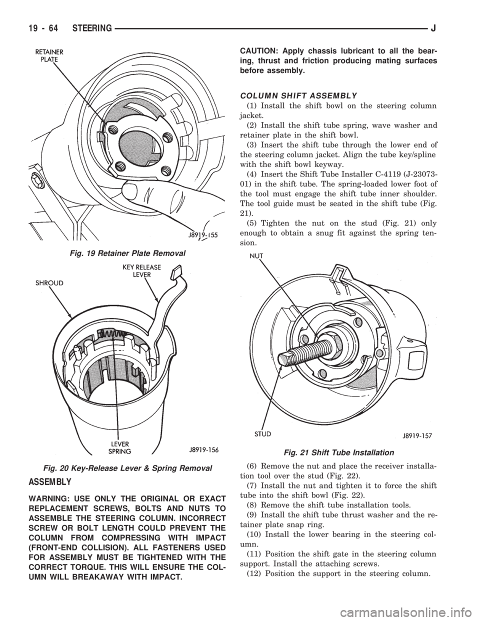
(4) Insert the Shift Tube Installer C-4119 (J-23073-
01) in the shift tube. The spring-loaded lower foot of
the tool must engage the shift tube inner shoulder.
The tool guide must be seated in the shift tube (Fig.
21).
(5) Tighten the nut on the stud (Fig. 21) only
enough to obtain a snug fit against the spring ten-
sion.
(6) Remove the nut and place the receiver installa-
tion tool over the stud (Fig. 22).
(7) Install the nut and tighten it to force the shift
tube into the shift bowl (Fig. 22).
(8) Remove the shift tube installation tools.
(9) Install the shift tube thrust washer and the re-
tainer plate snap ring.
(10) Install the lower bearing in the steering col-
umn.
(11) Position the shift gate in the steering column
support. Install the attaching screws.
(12) Position the support in the steering column.
Fig. 19 Retainer Plate Removal
Fig. 20 Key-Release Lever & Spring Removal
Fig. 21 Shift Tube Installation
19 - 64 STEERINGJ
Page 1102 of 1784
(13) Install all support attaching screws finger-
tight. Next, tighten the screws alternately and evenly
to7Nzm (60 in. lbs.) torque.
(14) Install the remote rod in the support. Route
the rod through the upper end of the shroud and in-
sert it into the rod slot located in the support.
(15) Install the dimmer switch and ignition switch.
(16) Install the steering shaft in the steering col-
umn.
(17) Install replacement races and bearings in the
key/lock cylinder, if removed.Ensure that the bear-
ings are lubricated with chassis lubricant be-
fore installation.
(18) Install the lock shoes, the lock shoe springs
and the lock shoe pin the key/lock cylinder housing.
Use a 4.5-mm (0.18-in) diameter rod to align the
shoes and the pin during installation.
(19) Install the tilt-release lever, the lever spring
and the lever pin in the key/lock cylinder housing.
Insert a wedge between the housing and the lever to
relieve the spring tension. This will allow easier re-
lease lever pin installation.
(20) Install the lock bolt in the key/lock cylinder
housing and engage it in the lock sector cam surface.
(21) Install the lock rack, the rack preload spring
and a replacement shim in the key/lock cylinder
housing. Align and mate the square block tooth on
the lock rack and the lock sector.
(22) Install the lock spring and the spring retain-
ing screw. Tighten the screw to 4 Nzm (35 in. lbs.)
torque.
(23) Align and install the assembled key/lock cylin-
der housing on the support. Retain the lock shoes in
the disengaged position for easier housing installa-
tion.(24) Align the pivot pin holes in the housing with
those in the support. Insert the pivot pins.Press the
housing firmly downward when inserting the
pivot pins. This prevents damaging the holes in
the support.When the pivot pins are within both
the housing and the support holes, seat them fully
with a punch and a hammer.
(25) Insert tilt-release lever in key/lock cylinder
housing and place housing in the full-upward tilt po-
sition.
(26) Lubricate the tilt spring guide and the tilt
spring liberally with chassis lubricant and position
the spring on the guide.
(27) Insert the tilt spring guide and the spring into
the key/lock cylinder housing. Install the guide re-
tainer over the spring. Engage the retainer lock tabs
with the housing lugs by pressing the retainer down-
ward and turning clockwise with a screwdriver.
(28) Place the cover on the key/lock cylinder hous-
ing. Align and install the cover retaining screws.
Tighten the screws to 7 Nzm (60 in. lbs.) torque.
(29) Install the gear selector indicator lamp mount-
ing bracket screw.
(30) Install the gear selector indicator cover and
retaining screws.
(31) Route the dimmer switch wire harness and
gear selector indicator down through the steering col-
umn.
(32) To install ignition switch lock, turn the key to
the LOCK position and remove the key. This will
cause the buzzer operating lever to retract in the
key/lock cylinder. Now insert the key/lock cylinder
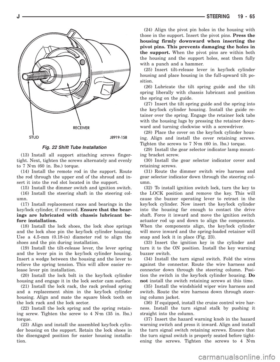
into the housing far enough to contact the drive
shaft. Force it inward and move the ignition switch
actuator rod up and down to align the components.
When the components align, the key/lock cylinder
will move inward and the spring-loaded retainer will
snap and lock it in place (Fig. 23).
(33) Insert the ignition key in the cylinder and
turn it to the ON position. Install the key warning
buzzer switch.
(34) Install the turn signal switch. Fold the wires
against the connector. Route the wire harness and
connector down through the steering column. Posi-
tion the switch in the key/lock cylinder housing.Do
notinstall the switch retaining screws at this time.
(35) Install the windshield wiper wire harness and
switch. Route the wire harness down through steer-
ing column jacket.
(36) If equipped, install the cruise control wire har-
ness. Install the turn signal stalk by pushing it
straight into the column.
(37) Insert the hazard warning knob in the hazard
warning switch and press it inward. Align and install
the turn signal switch retaining screws. Ensure that
the turn signal switch is properly seated before tight-
ening the screws. Tighten the screws to 4 Nzm
Fig. 22 Shift Tube Installation
JSTEERING 19 - 65
Page 1103 of 1784
(33 in. lbs.) torque. Thread the hazard warning
switch knob into the switch and pull the knob out-
ward.
(38) Install and seat the upper bearing race in the
key/lock cylinder housing.
(39) Install the upper bearing preload spring, the
canceling cam and the lockplate.
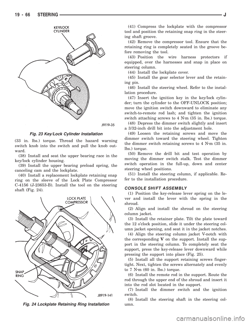
(40) Install a replacement lockplate retaining snap
ring on the sleeve of the Lock Plate Compressor
C-4156 (J-23653-B). Install the tool on the steering
shaft (Fig. 24).(41) Compress the lockplate with the compressor
tool and position the retaining snap ring in the steer-
ing shaft groove.
(42) Remove the compressor tool. Ensure that the
retaining ring is completely seated in the groove be-
fore removing the tool.
(43) Position the wire harness protectors if
equipped, over the harnesses and snap in place on
steering column.
(44) Install the lockplate cover.
(45) Install the gear selector lever and the retain-
ing pin.
(46) Install the steering wheel. Refer to the instal-
lation procedure.
(47) Insert the ignition key in the key/lock cylin-
der; turn the cylinder to the OFF-UNLOCK position;
move the ignition switch downward to eliminate any
switch-to-remote rod lash; and tighten the ignition
switch attaching screws to 4 Nzm (35 in. lbs.) torque.
(48) Depress the dimmer switch slightly and insert
a 3/32-inch drill bit into the adjustment hole.
(49) Loosen the retaining screws and move the
dimmer switch toward the steering wheel. Tighten
the dimmer switch retaining screws to 4 Nzm (35 in.
lbs.) torque.
(50) Remove the drill bit and test operation by
moving the dimmer switch stalk. Test the dimmer
switch operation in the full-up, down and center
steering wheel positions.
(51) Install the steering column, if applicable. Re-
fer to the installation procedure.
CONSOLE SHIFT ASSEMBLY
(1) Position the key-release lever spring on the le-
ver and install the lever with the spring in the
shroud.
(2) Align and install the shroud on the steering
column jacket.
(3) Install the retainer plate. Tilt the plate toward
the 12 o'clock position, slide it under the steering col-
umn jacket opening, and seat it in the jacket notches.
(4) Align the steering column jacket V-notch with
the correspondingVon the support. Install the sup-
port in the steering column. To completely seat the
support, press the key-release lever downward while
pressing the support into place (Fig. 25).
(5) Install all the support retaining screws finger-
tight. Next, tighten the screws alternately and evenly
to7Nzm (60 in. lbs.) torque.
(6) Install the remote rod in the support. Route the
rod through the upper end of the shroud and insert it
into the rod slot located in the support.
(7) Install the dimmer switch and the ignition
switch.
(8) Install the steering shaft in the steering col-
umn.
Fig. 23 Key/Lock Cylinder Installation
Fig. 24 Lockplate Retaining Ring Installation
19 - 66 STEERINGJ