1994 JEEP CHEROKEE warning
[x] Cancel search: warningPage 1354 of 1784
(2) Remove oil strainers (Fig. 2).
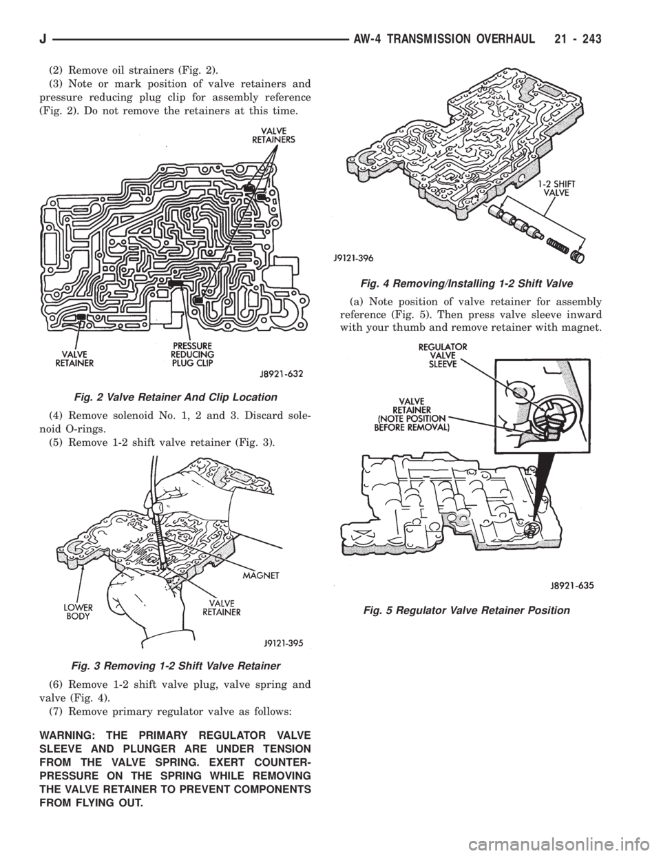
(3) Note or mark position of valve retainers and
pressure reducing plug clip for assembly reference
(Fig. 2). Do not remove the retainers at this time.
(4) Remove solenoid No. 1, 2 and 3. Discard sole-
noid O-rings.
(5) Remove 1-2 shift valve retainer (Fig. 3).
(6) Remove 1-2 shift valve plug, valve spring and
valve (Fig. 4).
(7) Remove primary regulator valve as follows:
WARNING: THE PRIMARY REGULATOR VALVE
SLEEVE AND PLUNGER ARE UNDER TENSION
FROM THE VALVE SPRING. EXERT COUNTER-
PRESSURE ON THE SPRING WHILE REMOVING
THE VALVE RETAINER TO PREVENT COMPONENTS
FROM FLYING OUT.(a) Note position of valve retainer for assembly
reference (Fig. 5). Then press valve sleeve inward
with your thumb and remove retainer with magnet.
Fig. 2 Valve Retainer And Clip Location
Fig. 3 Removing 1-2 Shift Valve Retainer
Fig. 4 Removing/Installing 1-2 Shift Valve
Fig. 5 Regulator Valve Retainer Position
JAW-4 TRANSMISSION OVERHAUL 21 - 243
Page 1445 of 1784
TIRE CHAINS
Tire snow chains may be used on certain models.
Refer to Owner's Manual for more information.
CLEANING OF TIRES
Steam cleaning may be used for cleaning.
DO NOT use gasoline or wire brush for cleaning.
DO NOT use mineral oil or an oil-based solvent.
PRESSURE GAUGES
High-quality, dial-type, air-pressure gauges are
recommended. After checking with the gauge, re-
place valve cap and finger tight.
TIRE INFLATION PRESSURES
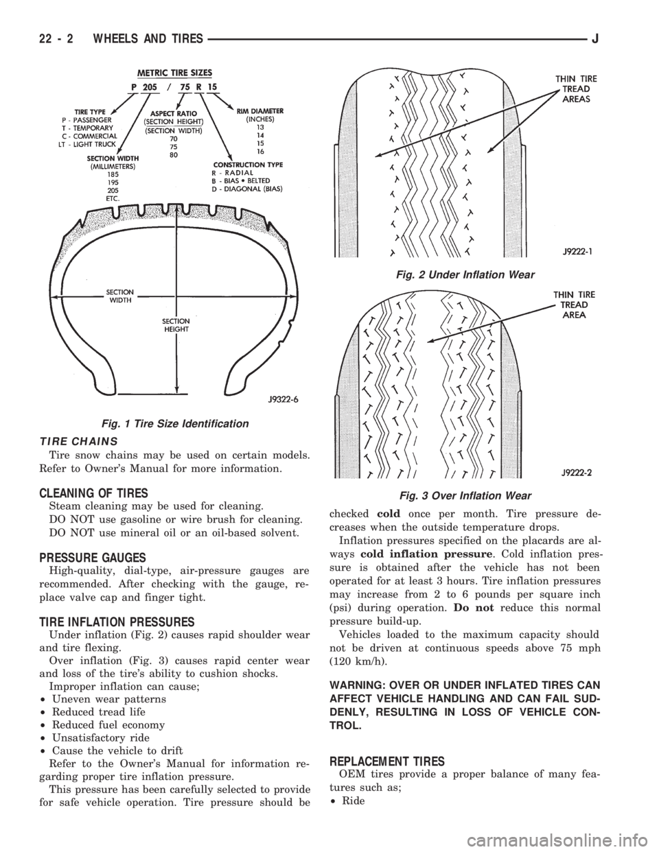
Under inflation (Fig. 2) causes rapid shoulder wear
and tire flexing.
Over inflation (Fig. 3) causes rapid center wear
and loss of the tire's ability to cushion shocks.
Improper inflation can cause;
²Uneven wear patterns
²Reduced tread life
²Reduced fuel economy
²Unsatisfactory ride
²Cause the vehicle to drift
Refer to the Owner's Manual for information re-
garding proper tire inflation pressure.
This pressure has been carefully selected to provide
for safe vehicle operation. Tire pressure should becheckedcoldonce per month. Tire pressure de-
creases when the outside temperature drops.
Inflation pressures specified on the placards are al-
wayscold inflation pressure. Cold inflation pres-
sure is obtained after the vehicle has not been
operated for at least 3 hours. Tire inflation pressures
may increase from 2 to 6 pounds per square inch
(psi) during operation.Do notreduce this normal
pressure build-up.
Vehicles loaded to the maximum capacity should
not be driven at continuous speeds above 75 mph
(120 km/h).
WARNING: OVER OR UNDER INFLATED TIRES CAN
AFFECT VEHICLE HANDLING AND CAN FAIL SUD-
DENLY, RESULTING IN LOSS OF VEHICLE CON-
TROL.
REPLACEMENT TIRES
OEM tires provide a proper balance of many fea-
tures such as;
²Ride
Fig. 1 Tire Size Identification
Fig. 2 Under Inflation Wear
Fig. 3 Over Inflation Wear
22 - 2 WHEELS AND TIRESJ
Page 1446 of 1784
²Noise
²Handling
²Durability
²Tread life
²Traction
²Rolling resistance
²Speed capability
Original equipment tires should be used when re-
placement is needed.
Refer to the placard on the vehicle or the
Owner's Manual for the correct replacement
tire.
Failure to use original or equivalent replacement
tires may adversely affect the handling of the vehi-
cle.
The use of oversize tiresis not recommended.
They may cause interference with vehicle suspension
and steering travel. This can cause tire damage or
failure.
WARNING: FAILURE TO EQUIP THE VEHICLE WITH
TIRES HAVING ADEQUATE LOAD CAPABILITY CAN
RESULT IN SUDDEN TIRE FAILURE.
ROTATION
Tires on the front and rear axles operate at differ-
ent loads and perform different steering, driving, and
braking functions. For these reasons, the tires wear
at unequal rates. They may also develop irregular
wear patterns. These effects can be reduced by rotat-
ing the tires according to the maintenance schedule
in the Owners Manual. This will improve tread life,
traction and maintain a smooth quiet ride.
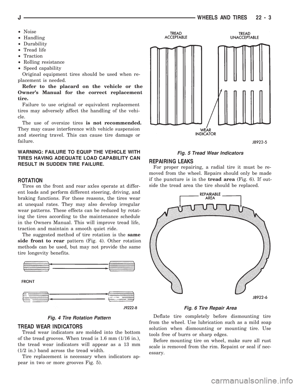
The suggested method of tire rotation is thesame
side front to rearpattern (Fig. 4). Other rotation
methods can be used, but may not provide the same
tire longevity benefits.
TREAD WEAR INDICATORS
Tread wear indicators are molded into the bottom
of the tread grooves. When tread is 1.6 mm (1/16 in.),
the tread wear indicators will appear as a 13 mm
(1/2 in.) band across the tread width.
Tire replacement is necessary when indicators ap-
pear in two or more grooves Fig. 5).
REPAIRING LEAKS
For proper repairing, a radial tire it must be re-
moved from the wheel. Repairs should only be made
if the puncture is in thetread area(Fig. 6). If out-
side the tread area the tire should be replaced.
Deflate tire completely before dismounting tire
from the wheel. Use lubrication such as a mild soap
solution when dismounting or mounting tire. Use
tools free of burrs or sharp edges.
Before mounting tire on wheel, make sure all rust
scale is removed from the rim. Repaint or seal if nec-
essary.
Fig. 4 Tire Rotation Pattern
Fig. 5 Tread Wear Indicators
Fig. 6 Tire Repair Area
JWHEELS AND TIRES 22 - 3
Page 1449 of 1784
WHEELS
GENERAL INFORMATION
Original equipment wheels are designed for the
specified Maximum Vehicle Capacity.
All models use steel or cast aluminum drop center
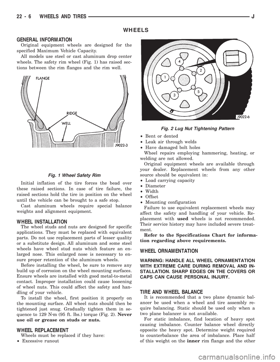
wheels. The safety rim wheel (Fig. 1) has raised sec-
tions between the rim flanges and the rim well.
Initial inflation of the tire forces the bead over
these raised sections. In case of tire failure, the
raised sections hold the tire in position on the wheel
until the vehicle can be brought to a safe stop.
Cast aluminum wheels require special balance
weights and alignment equipment.
WHEEL INSTALLATION
The wheel studs and nuts are designed for specific
applications. They must be replaced with equivalent
parts. Do not use replacement parts of lesser quality
or a substitute design. All aluminum and some steel
wheels have wheel stud nuts which feature an en-
larged nose. This enlarged nose is necessary to en-
sure proper retention of the aluminum wheels.
Before installing the wheel, be sure to remove any
build up of corrosion on the wheel mounting surfaces.
Ensure wheels are installed with good metal-to-metal
contact. Improper installation could cause loosening
of wheel nuts. This could affect the safety and han-
dling of your vehicle.
To install the wheel, first position it properly on
the mounting surface. All wheel nuts should then be
tightened just snug. Gradually tighten them in se-
quence to 129 Nzm (95 ft. lbs.) torque (Fig. 2).Never
use oil or grease on studs or nuts.
WHEEL REPLACEMENT
Wheels must be replaced if they have:
²Excessive runout²Bent or dented
²Leak air through welds
²Have damaged bolt holes
Wheel repairs employing hammering, heating, or
welding are not allowed.
Original equipment wheels are available through
your dealer. Replacement wheels from any other
source should be equivalent in:
²Load carrying capacity
²Diameter
²Width
²Offset
²Mounting configuration
Failure to use equivalent replacement wheels may
affect the safety and handling of your vehicle. Re-
placement withusedwheels is not recommended.
Their service history may have included severe treat-
ment.
Refer to the Specifications Chart for informa-
tion regarding above requirements.
WHEEL ORNAMENTATION
WARNING: HANDLE ALL WHEEL ORNAMENTATION
WITH EXTREME CARE DURING REMOVAL AND IN-
STALLATION. SHARP EDGES ON THE COVERS OR
CAPS CAN CAUSE PERSONAL INJURY.
TIRE AND WHEEL BALANCE
It is recommended that a two plane dynamic bal-
ancer be used when a wheel and tire assembly re-
quire balancing. Static should be used only when a
two plane balancer is not available.
For static imbalance, find location of heavy spot
causing imbalance. Counter balance wheel directly
opposite the heavy spot. Determine weight required
to counterbalance the area of imbalance. Place half
of this weight on theinnerrim flange and the other
Fig. 2 Lug Nut Tightening Pattern
Fig. 1 Wheel Safety Rim
22 - 6 WHEELS AND TIRESJ
Page 1477 of 1784
(2) Carefully pry the applique off the license plate
visor and tailgate (Fig. 62).
INSTALLATION
(1) Align the moulding with the visor and then
press the applique into place.
(2) Install the rivets to attach the outboard tabs on
applique to the tailgate.
WOODGRAIN OVERLAY
SERVICE INFORMATION
Exterior woodgrain overlay is a weather-resistant
vinyl. The adhesive backing is protected by a paper
liner until removed for installation.
OVERLAY REPAIR
Small nicks and scratches on an overlay can be
touched-up with paint.
To eliminate blisters and air bubbles, pierce them
with a needle or pin. Force the trapped air out of the
hole and press firmly on the overlay. Heat also can
be applied to remove small wrinkles.
Whenever an overlay must be stretched, do
not slit or cut it. Instead, apply heat and press
or squeegee the overlay into place.
INSTALLATION REQUIREMENTS
Overlay replacement requires metal repair and
paint refinish to be completed before the overlay is
installed.
The work area temperature should be between
18ÉC (65ÉF) and 32ÉC (90ÉF).A woodgrain overlay
should not be replaced if the work area temper-
ature is less than 18ÉC (65ÉF).
The following equipment and material are neces-
sary for overlay installation:
²a commercial woodgrain overlay removal solution;
²a commercial adhesive removal solution;
²liquid dish detergent (for wetting solution);
²a mixture of wetting solution;
²a commercial wax and silicone removal solution;
²isopropyl alcohol (rubbing alcohol);
²a squeegee (4 to 5 inches wide, plastic or hard rub-
ber);
²a water bucket and sponge;
²sandpaper (no. 360 or no. 400, wet or dry type);
²a heat gun (or infra-red heat bulb);
²clean wiping rags or paper towels;
²a pair of scissors;
²a needle or pin; and
²a wax pencil.
Using a wetting solution helps the installation of
an overlay. Prepare a solution by mixing two or three
teaspoons of dish detergent with 1 gallon of water.
Do not use soap.
Too much detergent will reduce the effective-
ness of the mixture.
OVERLAY REMOVAL
(1) Remove the adjacent moulding from panel.
(2) Start at one corner and apply heat with a heat
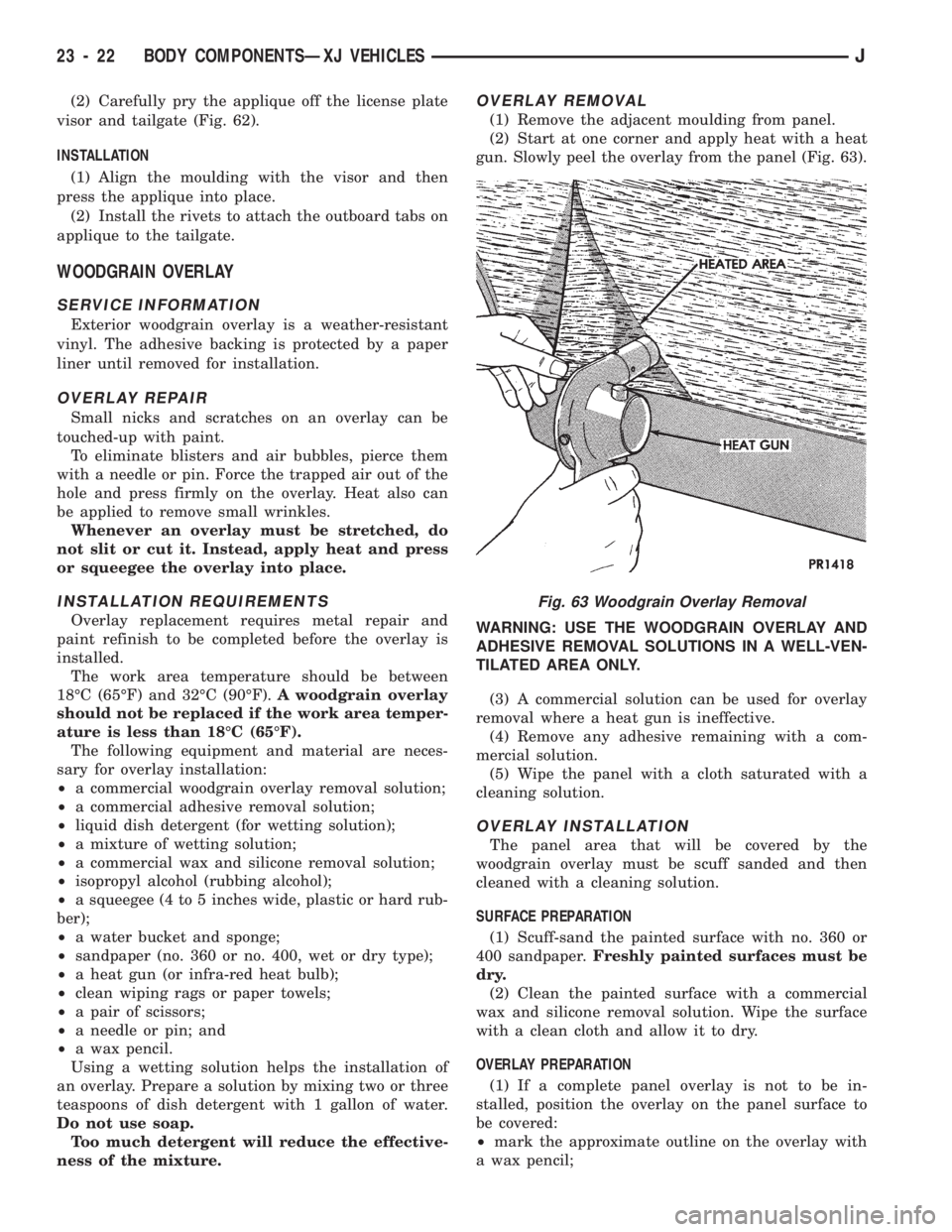
gun. Slowly peel the overlay from the panel (Fig. 63).
WARNING: USE THE WOODGRAIN OVERLAY AND
ADHESIVE REMOVAL SOLUTIONS IN A WELL-VEN-
TILATED AREA ONLY.
(3) A commercial solution can be used for overlay
removal where a heat gun is ineffective.
(4) Remove any adhesive remaining with a com-
mercial solution.
(5) Wipe the panel with a cloth saturated with a
cleaning solution.
OVERLAY INSTALLATION
The panel area that will be covered by the
woodgrain overlay must be scuff sanded and then
cleaned with a cleaning solution.
SURFACE PREPARATION
(1) Scuff-sand the painted surface with no. 360 or
400 sandpaper.Freshly painted surfaces must be
dry.
(2) Clean the painted surface with a commercial
wax and silicone removal solution. Wipe the surface
with a clean cloth and allow it to dry.
OVERLAY PREPARATION
(1) If a complete panel overlay is not to be in-
stalled, position the overlay on the panel surface to
be covered:
²mark the approximate outline on the overlay with
a wax pencil;
Fig. 63 Woodgrain Overlay Removal
23 - 22 BODY COMPONENTSÐXJ VEHICLESJ
Page 1480 of 1784
FUEL FILLER DOOR OVERLAY APPLICATION
(1) Clean the door flange with an appropriate solu-
tion.
(2) Position the top edge of the overlay at the char-
acter line and notches at door edge.
(3) Wipe the adhesive side of fuel filler door over-
lay edges with isopropyl alcohol.
(4) Heat the door overlay edges with a heat gun to
soften and make them more pliable.
CAUTION: Avoid unnecessary pulling and stretch-
ing at the ends.
(5) Fold the overlay edges over onto the door panel
flange areas and press them into place.
LIFTGATE OVERLAY APPLICATION
(1) Position the top edge of the overlay at charac-
ter line and inner edges at the license plate recess.
(2) Wipe the adhesive side of the liftgate overlay
edges with isopropyl alcohol.
(3) Heat the liftgate overlay edges with a heat gun
to soften and make them more pliable.
CAUTION: Avoid unnecessary pulling and stretch-
ing at the ends.
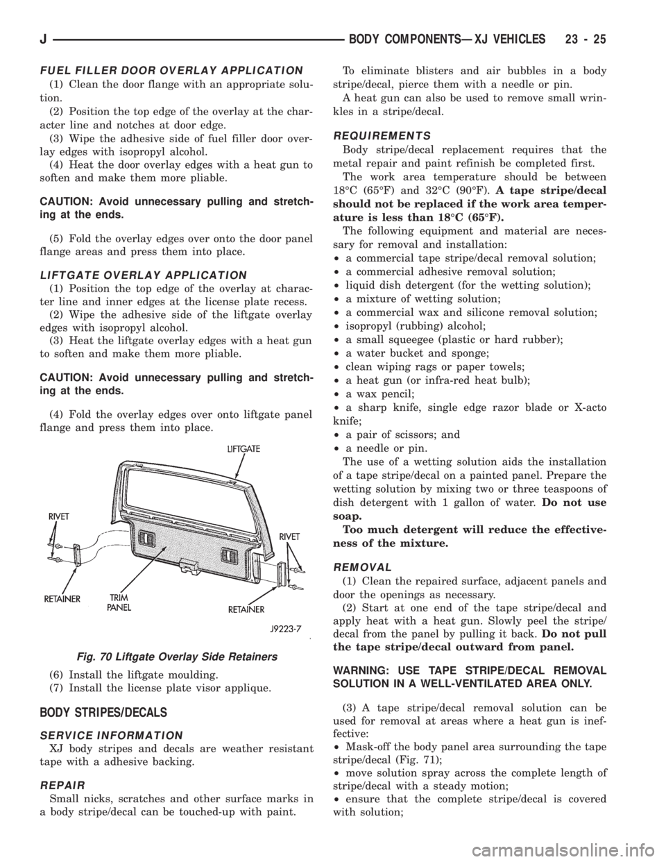
(4) Fold the overlay edges over onto liftgate panel
flange and press them into place.
(6) Install the liftgate moulding.
(7) Install the license plate visor applique.
BODY STRIPES/DECALS
SERVICE INFORMATION
XJ body stripes and decals are weather resistant
tape with a adhesive backing.
REPAIR
Small nicks, scratches and other surface marks in
a body stripe/decal can be touched-up with paint.To eliminate blisters and air bubbles in a body
stripe/decal, pierce them with a needle or pin.
A heat gun can also be used to remove small wrin-
kles in a stripe/decal.
REQUIREMENTS
Body stripe/decal replacement requires that the
metal repair and paint refinish be completed first.
The work area temperature should be between
18ÉC (65ÉF) and 32ÉC (90ÉF).A tape stripe/decal
should not be replaced if the work area temper-
ature is less than 18ÉC (65ÉF).
The following equipment and material are neces-
sary for removal and installation:
²a commercial tape stripe/decal removal solution;
²a commercial adhesive removal solution;
²liquid dish detergent (for the wetting solution);
²a mixture of wetting solution;
²a commercial wax and silicone removal solution;
²isopropyl (rubbing) alcohol;
²a small squeegee (plastic or hard rubber);
²a water bucket and sponge;
²clean wiping rags or paper towels;
²a heat gun (or infra-red heat bulb);
²a wax pencil;
²a sharp knife, single edge razor blade or X-acto
knife;
²a pair of scissors; and
²a needle or pin.
The use of a wetting solution aids the installation
of a tape stripe/decal on a painted panel. Prepare the
wetting solution by mixing two or three teaspoons of
dish detergent with 1 gallon of water.Do not use
soap.
Too much detergent will reduce the effective-
ness of the mixture.
REMOVAL
(1) Clean the repaired surface, adjacent panels and
door the openings as necessary.
(2) Start at one end of the tape stripe/decal and
apply heat with a heat gun. Slowly peel the stripe/
decal from the panel by pulling it back.Do not pull
the tape stripe/decal outward from panel.
WARNING: USE TAPE STRIPE/DECAL REMOVAL
SOLUTION IN A WELL-VENTILATED AREA ONLY.
(3) A tape stripe/decal removal solution can be
used for removal at areas where a heat gun is inef-
fective:
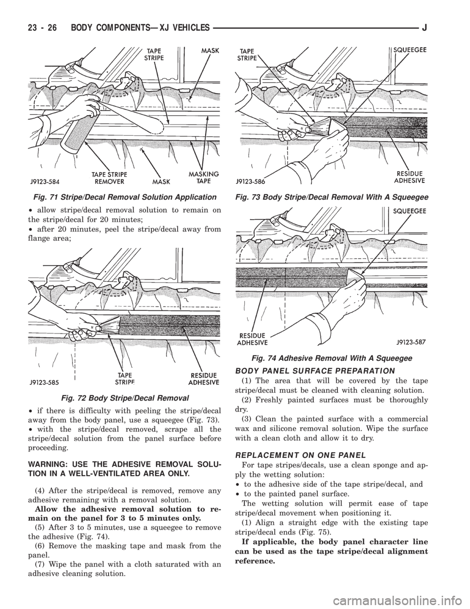
²Mask-off the body panel area surrounding the tape
stripe/decal (Fig. 71);
²move solution spray across the complete length of
stripe/decal with a steady motion;
²ensure that the complete stripe/decal is covered
with solution;
Fig. 70 Liftgate Overlay Side Retainers
JBODY COMPONENTSÐXJ VEHICLES 23 - 25
Page 1481 of 1784
²allow stripe/decal removal solution to remain on
the stripe/decal for 20 minutes;
²after 20 minutes, peel the stripe/decal away from
flange area;
²if there is difficulty with peeling the stripe/decal
away from the body panel, use a squeegee (Fig. 73).
²with the stripe/decal removed, scrape all the
stripe/decal solution from the panel surface before
proceeding.
WARNING: USE THE ADHESIVE REMOVAL SOLU-
TION IN A WELL-VENTILATED AREA ONLY.
(4) After the stripe/decal is removed, remove any
adhesive remaining with a removal solution.
Allow the adhesive removal solution to re-
main on the panel for 3 to 5 minutes only.
(5) After 3 to 5 minutes, use a squeegee to remove
the adhesive (Fig. 74).
(6) Remove the masking tape and mask from the
panel.
(7) Wipe the panel with a cloth saturated with an
adhesive cleaning solution.
BODY PANEL SURFACE PREPARATION
(1) The area that will be covered by the tape
stripe/decal must be cleaned with cleaning solution.
(2) Freshly painted surfaces must be thoroughly
dry.
(3) Clean the painted surface with a commercial
wax and silicone removal solution. Wipe the surface
with a clean cloth and allow it to dry.
REPLACEMENT ON ONE PANEL
For tape stripes/decals, use a clean sponge and ap-
ply the wetting solution:
²to the adhesive side of the tape stripe/decal, and
²to the painted panel surface.
The wetting solution will permit ease of tape
stripe/decal movement when positioning it.
(1) Align a straight edge with the existing tape
stripe/decal ends (Fig. 75).
If applicable, the body panel character line
can be used as the tape stripe/decal alignment
reference.
Fig. 71 Stripe/Decal Removal Solution Application
Fig. 72 Body Stripe/Decal Removal
Fig. 73 Body Stripe/Decal Removal With A Squeegee
Fig. 74 Adhesive Removal With A Squeegee
23 - 26 BODY COMPONENTSÐXJ VEHICLESJ
Page 1520 of 1784
LIFTGATE SERVICE INFORMATIONÐXJ VEHICLES
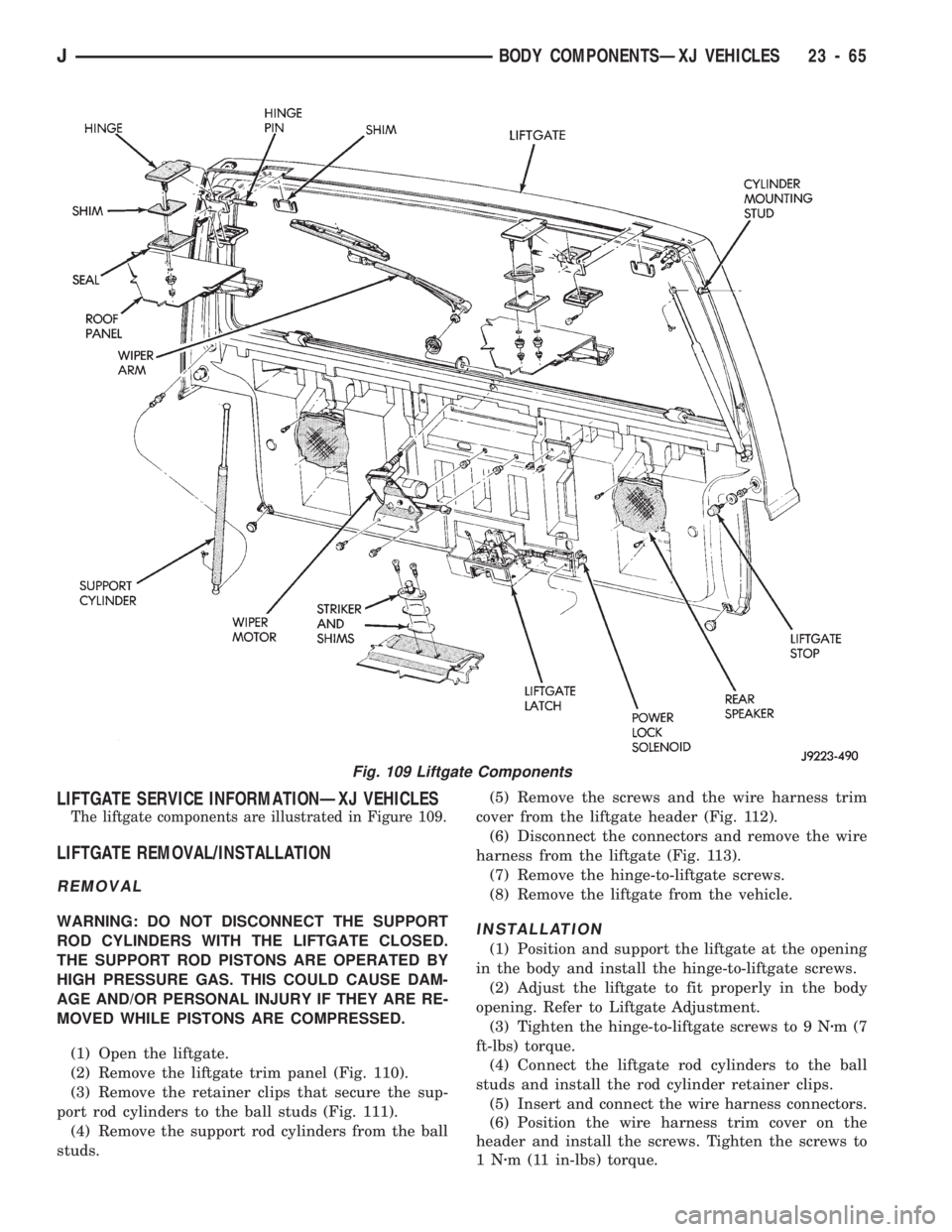
The liftgate components are illustrated in Figure 109.
LIFTGATE REMOVAL/INSTALLATION
REMOVAL
WARNING: DO NOT DISCONNECT THE SUPPORT
ROD CYLINDERS WITH THE LIFTGATE CLOSED.
THE SUPPORT ROD PISTONS ARE OPERATED BY
HIGH PRESSURE GAS. THIS COULD CAUSE DAM-
AGE AND/OR PERSONAL INJURY IF THEY ARE RE-
MOVED WHILE PISTONS ARE COMPRESSED.
(1) Open the liftgate.
(2) Remove the liftgate trim panel (Fig. 110).
(3) Remove the retainer clips that secure the sup-
port rod cylinders to the ball studs (Fig. 111).
(4) Remove the support rod cylinders from the ball
studs.(5) Remove the screws and the wire harness trim
cover from the liftgate header (Fig. 112).
(6) Disconnect the connectors and remove the wire
harness from the liftgate (Fig. 113).
(7) Remove the hinge-to-liftgate screws.
(8) Remove the liftgate from the vehicle.INSTALLATION
(1) Position and support the liftgate at the opening
in the body and install the hinge-to-liftgate screws.
(2) Adjust the liftgate to fit properly in the body
opening. Refer to Liftgate Adjustment.
(3) Tighten the hinge-to-liftgate screws to 9 Nzm(7
ft-lbs) torque.
(4) Connect the liftgate rod cylinders to the ball
studs and install the rod cylinder retainer clips.
(5) Insert and connect the wire harness connectors.
(6) Position the wire harness trim cover on the
header and install the screws. Tighten the screws to
1Nzm (11 in-lbs) torque.
Fig. 109 Liftgate Components
JBODY COMPONENTSÐXJ VEHICLES 23 - 65