1994 JEEP CHEROKEE warning
[x] Cancel search: warningPage 1104 of 1784
(9) Install replacement races and bearings in the
key/lock cylinder, if removed.Ensure that the bear-
ings are lubricated with chassis lubricant be-
fore installation.
(10) Install the lock shoes, the lock shoe springs
and the lock shoe pin the key/lock cylinder housing.
Use a 4.5-mm (0.18-in) diameter rod to align the
shoes and the pin during installation.
(11) Install the tilt-release lever, the lever spring
and the lever pin in the key/lock cylinder housing.
Insert a wedge between the housing and the lever to
relieve the spring tension. This will allow easier re-
lease lever pin installation.
(12) Install the lock bolt in the key/lock cylinder
housing and engage it in the lock sector cam surface.
(13) Install the lock rack, the rack preload spring
and a replacement shim in the key/lock cylinder
housing. The square block tooth on the lock rack and
lock sector must mate.
(14) Install the lock spring and the spring retain-
ing screw. Tighten the screw to 4 Nzm (35 in. lbs.)
torque.
(15) Align and install the assembled key/lock cylin-
der housing on the support. Retain the lock shoes in
the disengaged position for easier housing installa-
tion.
(16) Align the pivot pin holes in the key/lock cylin-
der housing with those in the support and insert the
pivot pins.Press the housing firmly downward
when inserting the pivot pins to prevent dam-
aging the holes in the support.When the pivot
pins are within both the housing and the support
holes, seat them fully with a punch and a hammer.(17) Insert the tilt-release lever in the key/lock cyl-
inder housing and place the housing in the full-up-
ward tilt position.
(18) Lubricate tilt spring guide and tilt spring lib-
erally with chassis lubricant. Then position spring on
guide.
(19) Insert the tilt spring guide and the spring into
the key/lock cylinder housing. Install the guide re-
tainer over the spring. Engage the retainer lock tabs
with the housing lugs by pressing the retainer down-
ward and turning clockwise with a screwdriver.
(20) Place the cover on the key/lock cylinder hous-
ing. Align and install the cover retaining screws.
Tighten the screws to 7 Nzm (60 in. lbs.) torque.
(21) Route the dimmer switch wire harness down
through the steering column.
(22) To install ignition switch lock, turn the key to
the LOCK position and remove the key. This will
cause the buzzer operating lever to retract in the
key/lock cylinder. Now insert the key/lock cylinder
into the housing far enough to contact the drive
shaft. Force it inward and move the ignition switch
actuator rod up and down to align the components.
When the components align, the key/lock cylinder
will move inward and the spring-loaded retainer will
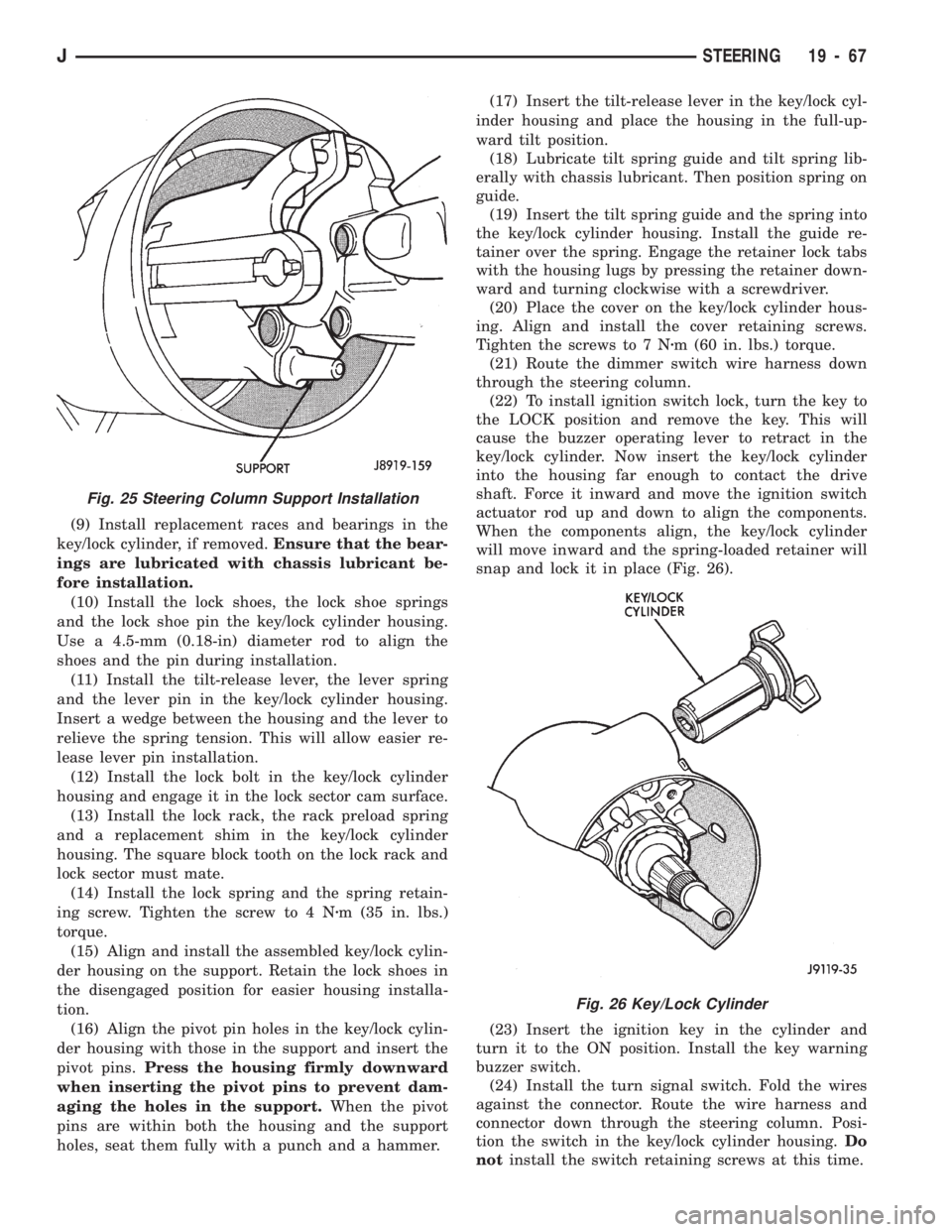
snap and lock it in place (Fig. 26).
(23) Insert the ignition key in the cylinder and
turn it to the ON position. Install the key warning
buzzer switch.
(24) Install the turn signal switch. Fold the wires
against the connector. Route the wire harness and
connector down through the steering column. Posi-
tion the switch in the key/lock cylinder housing.Do
notinstall the switch retaining screws at this time.
Fig. 26 Key/Lock Cylinder
Fig. 25 Steering Column Support Installation
JSTEERING 19 - 67
Page 1105 of 1784
(25) Install the windshield wiper wire harness and
switch. Route the wire harness down through steer-
ing column jacket.
(26) If equipped, install the cruise control wire har-
ness. Install the turn signal stalk by pushing it
straight into the column.
(27) Insert the hazard warning knob in the hazard
warning switch and press it inward. Align and install
the turn signal switch retaining screws. Ensure that
the turn signal switch is properly seated before tight-
ening the screws. Tighten the screws to 4 Nzm (33 in.
lbs.) torque. Thread the hazard warning switch knob
into the switch and pull the knob outward.
(28) Install and seat the upper bearing race in the
key/lock cylinder housing.
(29) Install the upper bearing preload spring, the
canceling cam and the lockplate.
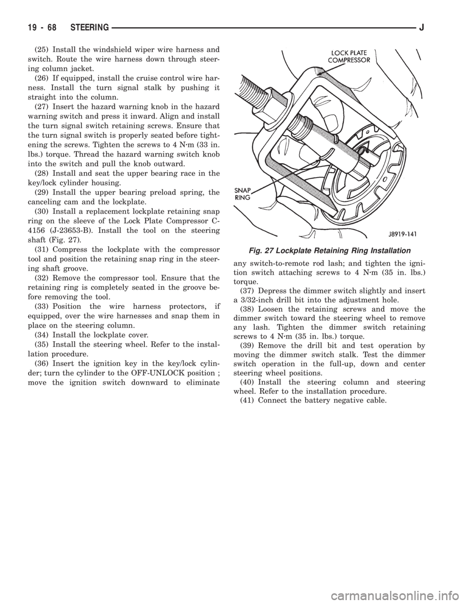
(30) Install a replacement lockplate retaining snap
ring on the sleeve of the Lock Plate Compressor C-
4156 (J-23653-B). Install the tool on the steering
shaft (Fig. 27).
(31) Compress the lockplate with the compressor
tool and position the retaining snap ring in the steer-
ing shaft groove.
(32) Remove the compressor tool. Ensure that the
retaining ring is completely seated in the groove be-
fore removing the tool.
(33) Position the wire harness protectors, if
equipped, over the wire harnesses and snap them in
place on the steering column.
(34) Install the lockplate cover.
(35) Install the steering wheel. Refer to the instal-
lation procedure.
(36) Insert the ignition key in the key/lock cylin-
der; turn the cylinder to the OFF-UNLOCK position ;
move the ignition switch downward to eliminateany switch-to-remote rod lash; and tighten the igni-
tion switch attaching screws to 4 Nzm (35 in. lbs.)
torque.
(37) Depress the dimmer switch slightly and insert
a 3/32-inch drill bit into the adjustment hole.
(38) Loosen the retaining screws and move the
dimmer switch toward the steering wheel to remove
any lash. Tighten the dimmer switch retaining
screws to 4 Nzm (35 in. lbs.) torque.
(39) Remove the drill bit and test operation by
moving the dimmer switch stalk. Test the dimmer
switch operation in the full-up, down and center
steering wheel positions.
(40) Install the steering column and steering
wheel. Refer to the installation procedure.
(41) Connect the battery negative cable.
Fig. 27 Lockplate Retaining Ring Installation
19 - 68 STEERINGJ
Page 1106 of 1784
STEERING RHD
GENERAL SERVICE PROCEDURE INFORMATION
Right hand drive service procedures and torque
specifications involving steering; linkage, gear and
column are the same as left hand drive vehicles ex-
cept where shown. Refer to appropriate service proce-
dures regarding each component in the system.
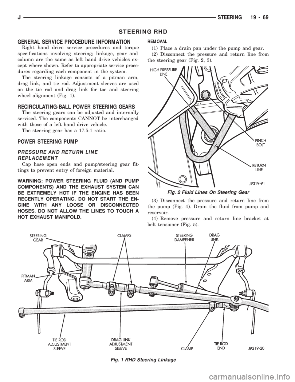
The steering linkage consists of a pitman arm,
drag link, and tie rod. Adjustment sleeves are used
on the tie rod and drag link for toe and steering
wheel alignment (Fig. 1).
RECIRCULATING-BALL POWER STEERING GEARS
The steering gears can be adjusted and internally
serviced. The components CANNOT be interchanged
with those of a left hand drive vehicle.
The steering gear has a 17.5:1 ratio.
POWER STEERING PUMP
PRESSURE AND RETURN LINE
REPLACEMENT
Cap hose open ends and pump/steering gear fit-
tings to prevent entry of foreign material.
WARNING: POWER STEERING FLUID (AND PUMP
COMPONENTS) AND THE EXHAUST SYSTEM CAN
BE EXTREMELY HOT IF THE ENGINE HAS BEEN
RECENTLY OPERATING. DO NOT START THE EN-
GINE WITH ANY LOOSE OR DISCONNECTED
HOSES. DO NOT ALLOW THE LINES TO TOUCH A
HOT EXHAUST MANIFOLD.REMOVAL
(1) Place a drain pan under the pump and gear.
(2) Disconnect the pressure and return line from
the steering gear (Fig. 2, 3).
(3) Disconnect the pressure and return line from
the pump (Fig. 4). Drain the fluid from pump and
reservoir.
(4) Remove pressure and return line bracket at
belt tensioner (Fig. 5).
Fig. 1 RHD Steering Linkage
Fig. 2 Fluid Lines On Steering Gear
JSTEERING 19 - 69
Page 1180 of 1784
30RH/32RH TRANSMISSION DIAGNOSIS
INDEX
page page
Air Pressure Test........................ 73
Analyzing the Road Test................... 70
Converter Housing Leak Diagnosis........... 73
Converter Stall Test...................... 72
Diagnosis Guides and Charts............... 76
Fluid Level and Condition.................. 69Gearshift Linkage........................ 70
General Information....................... 69
Hydraulic Pressure Test................... 71
Preliminary Diagnosis..................... 69
Road Test.............................. 70
Transmission Throttle Valve Cable Adjustment . . 70
GENERAL INFORMATION
Automatic transmission problems are generally the
result of:
²poor engine performance
²incorrect fluid level
²incorrect cable/linkage adjustment
²incorrect band adjustment
²incorrect hydraulic control pressure adjustments
²hydraulic component malfunctions
²mechanical component malfunctions.
Begin diagnosis by checking the easily accessible
items such as fluid level, fluid condition and control
linkage adjustment. A road test will determine if fur-
ther diagnosis is necessary.
Procedures outlined in this section should be per-
formed in the following sequence to realize the most
accurate results:
²Preliminary diagnosis
²Check fluid Level and condition
²Check control linkage Adjustment
²Road test
²Stall test
²Hydraulic pressure test
²Air pressure tests
²Leak Tests
²Analyze test results and consult diagnosis charts
PRELIMINARY DIAGNOSIS
Two basic procedures are required. One procedure
for vehicles that are driveable and an alternate pro-
cedure for disabled vehicles (will not back up or
move forward).
Vehicle Is Driveable
(1) Check fluid level and condition.
(2) Adjust throttle cable and gearshift linkage if
complaint was based on delayed, erratic, or harsh
shifts.
(3) Road test vehicle and note transmission operat-
ing characteristics.
(4) Perform stall test if complaint is based on slug-
gish, low speed acceleration or abnormal throttle
opening needed to maintain normal speeds with
properly tuned engine.
(5) Perform hydraulic pressure tests.(6) Perform air pressure test to check clutch-band
operation.
Vehicle Is Disabled
(1) Check fluid level and condition.
(2) Check for broken, disconnected throttle link-
age.
(3) Check for cracked, leaking cooler lines, or
loose, missing pressure port plugs.
(4) Raise vehicle, start engine, shift transmission
into gear and note following:
(a) If propeller shafts turn but wheels do not,
problem is with differential or axle shafts.
(b) If propeller shafts do not turn and transmis-
sion is noisy, stop engine. Remove oil pan, and
check for debris. If pan is clear, remove transmis-
sion and check for damaged drive plate, converter,
oil pump or input shaft.
(c) If propeller shafts do not turn and transmis-
sion is not noisy, perform hydraulic pressure test to
determine if problem is a hydraulic or mechanical.
FLUID LEVEL AND CONDITION
(1) Position vehicle on level surface. This is impor-
tant in obtaining an accurate fluid level check.
(2) To avoid false readings, which could produce
under or over fill condition, do not check level until
fluid is at normal operating temperature.
(3) Shift transmission into Neutral.
(4) Apply parking brakes.
(5) Operate engine at curb idle speed.
WARNING: WHEN PERFORMING UNDERHOOD OP-
ERATIONS WITH THE ENGINE RUNNING, KEEP
YOUR HANDS WELL AWAY FROM HOT OR ROTAT-
ING ENGINE COMPONENTS. DO NOT WEAR
LOOSE ARTICLES OF CLOTHING WHICH COULD
BECOME ENTANGLED IN ENGINE COMPONENTS
OR ACCESSORIES.
(6) Clean dipstick filler cap and tube before remov-
ing dipstick.
(7) Remove dipstick and inspect fluid level.
²Correct level is to FULL mark
²Acceptable level is between ADD and FULL marks
J30RH/32RH TRANSMISSION DIAGNOSIS 21 - 69
Page 1183 of 1784
(5) Line pressure should be 54-60 psi (372-414
kPa) with throttle lever forward and gradually in-
crease to 90-96 psi (620-662 kPa) as lever is moved
rearward.
Test Three-Transmission In D Range
This test checks pressure regulation and con-
dition of the front and rear clutch circuits.
Both test gauges are required for this test.
(1) Connect one test gauge to line pressure port
and other gauge to front servo pressure port (Fig. 4).
Either gauge can be used at either port.
(2) Start and run engine at 1600 rpm.
(3) Move selector lever two detents rearward from
full forward position. This is D range.
(4) Read pressures on both gauges as transmission
throttle lever is moved from full forward to full rear-
ward position.
(5) Line pressure should be 54-60 psi (372-414
kPa) with throttle lever forward and gradually in-
crease as lever is moved rearward.
(6) Front servo is pressurized only in D range and
should be same as line pressure within 3 psi (21
kPa), up to downshift point.
Test Four-Transmission In Reverse
This test checks pump output, pressure regu-
lation and the front clutch and rear servo cir-
cuits. Use 300 psi Pressure Test Gauge C-3293
for this test.
(1) Connect pressure test gauge to rear servo port
(Fig. 5).
(2) Start and run engine at 1600 rpm for test.
(3) Move valve body selector lever four detents
rearward from full forward position. This is Reverse
range.
(4) Move throttle lever all way forward then all the
way rearward and note gauge readings.
(5) Pressure should be 145 - 175 psi (1000-1207
kPa) with lever forward and increase to 230 - 280 psi
(1586-1931 kPa) as lever is moved rearward.
Test Five-Governor Pressure
This test checks governor operation by mea-
suring governor pressure response to changes
in engine speed. It is usually not necessary to
check governor operation unless shift speeds
are incorrect or if the transmission will not
shift up or down. Use 100 psi Pressure Test
Gauge C-3292 for this test.
(1) Connect test gauge to governor pressure port
(Figs. 5 and 6).
(2) Move selector lever to D range.
(3) Apply service brakes. Start and run engine at
curb idle speed and note pressure. At idle and with
wheels stopped, pressure should be zero to 1-1/2 psi
maximum. If pressure exceeds this figure, governor
valve or weights are sticking open.(4) Slowly increase engine speed and observe
speedometer and pressure test gauge. Governor pres-
sure should increase in proportion to vehicle speed
(approximately 1 psi for every 1 mph shown on
speedometer).
(5) Governor pressure rise should be smooth and
drop back to 0 to 1-1/2 psi when throttle is closed
and wheels are stopped.
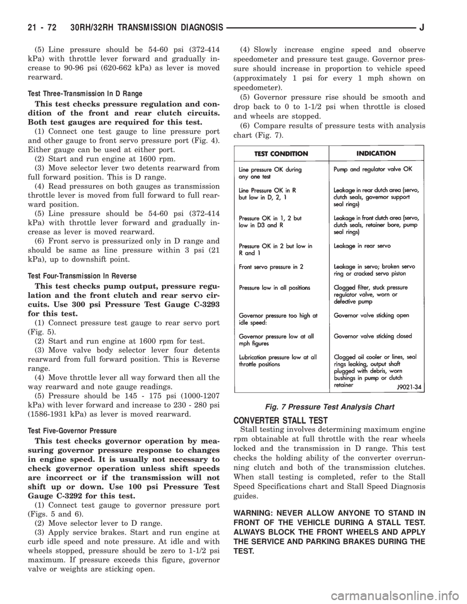
(6) Compare results of pressure tests with analysis
chart (Fig. 7).
CONVERTER STALL TEST
Stall testing involves determining maximum engine
rpm obtainable at full throttle with the rear wheels
locked and the transmission in D range. This test
checks the holding ability of the converter overrun-
ning clutch and both of the transmission clutches.
When stall testing is completed, refer to the Stall
Speed Specifications chart and Stall Speed Diagnosis
guides.
WARNING: NEVER ALLOW ANYONE TO STAND IN
FRONT OF THE VEHICLE DURING A STALL TEST.
ALWAYS BLOCK THE FRONT WHEELS AND APPLY
THE SERVICE AND PARKING BRAKES DURING THE
TEST.
Fig. 7 Pressure Test Analysis Chart
21 - 72 30RH/32RH TRANSMISSION DIAGNOSISJ
Page 1207 of 1784
30RH/32RH IN-VEHICLE SERVICE
INDEX
page page
Checking Fluid Level and Condition........... 96
Front Band Adjustment.................... 99
Gearshift Linkage Adjustment (YJ)............ 96
Governor and Park Gear Service............ 101
Oil Filter Replacement.................... 100
Park Interlock Cable Adjustment (XJ)......... 97
Park Lock Component Replacement......... 102
Park/Neutral Position Switch Service......... 103
Rear Band Adjustment.................... 99
Recommended Fluid...................... 96
Servicing Transmission Cooler Lines and Fittings. 106
Shift Cable Adjustment (XJ)................ 97
Speedometer Service.................... 103
Transmission Cooler Flow Testing........... 106
Transmission Cooler Reverse Flushing....... 105
Transmission Throttle Cable Adjustment (XJ/YJ) . 98
Valve Body Installation................... 101
Valve Body Removal..................... 100
Valve Body Service...................... 100
RECOMMENDED FLUID
The recommended and preferred fluid for 30RH/
32RH transmissions is Mopar ATF Plus, Type 7176.
Mopar Dexron II is acceptable but should only be
used when ATF Plus is not available.
Transmission fluid capacity is approximately 17
pints (7.9 liters). This is the approximate amount of
fluid required to fill the transmission and torque con-
verter after overhaul.
CHECKING FLUID LEVEL AND CONDITION
(1) Position vehicle on flat, level surface. This is
important in obtaining an accurate fluid level check.
(2) To avoid false readings, which could produce
under or over fill condition, do not check level until
fluid is at normal operating temperature.
(3) Shift transmission into Neutral.
(4) Apply parking brakes.
(5) Operate engine at curb idle speed.
WARNING: WHEN PERFORMING UNDERHOOD OP-
ERATIONS WITH THE ENGINE RUNNING, KEEP
YOUR HANDS WELL AWAY FROM HOT OR ROTAT-
ING ENGINE COMPONENTS. DO NOT WEAR
LOOSE ARTICLES OF CLOTHING WHICH COULD
BECOME ENTANGLED IN ENGINE COMPONENTS
OR ACCESSORIES.
(6) Shift transmission through all gear ranges and
back to Neutral (leave engine running).
(7) Clean exterior of dipstick cap and fill tube be-
fore removing transmission dipstick.
(8) Remove dipstick and inspect fluid level.
²Correct level is to FULL mark
²Acceptable level is between ADD and FULL marks
(9) Check fluid condition. Fluid should be dark to
light red in color and free of dirt or debris.
(10) If fluid is discolored or smells burned but
transmission operation was OK, check cooler flow,
flush cooler and lines and change fluid and filter.
Then road test again to confirm proper operation.(11) If fluid is black or dark brown, burned/turned
to sludge, contains large quantities of metal or fric-
tion material particles, transmission will need over-
haul. Especially if problems were evident during
road test and preliminary diagnosis. Fluid cooler
should also be flow tested and flushed if necessary.
GEARSHIFT LINKAGE ADJUSTMENT (YJ)
(1) Check linkage adjustment by starting engine in
Park and Neutral.
(2) Adjustment is OK if engine starts only in park
and Neutral. Adjustment is incorrect if engine starts
in one but not both positions.
(3) If engine starts in any position other than Park
or Neutral, or if engine will not start at all, park/
neutral position switch may be faulty.
(4) Shift transmission into Park.
(5) Raise vehicle.
(6) Check condition of shift rods, bellcrank, bell-
crank brackets and linkage bushings/grommets (Fig.
1). Tighten, repair, replace worn, damaged parts. Do
not attempt adjustment if linkage components are
worn or damaged.
(7) Loosen shift rod trunnion lock bolt or nut. Be
sure upper shift rod slides freely in trunnion (Fig. 1).
Also be sure shift rods and bellcrank rotate freely
and do not bind at any point.
(8) Verify that manual lever is in Park detent
(Fig. 1). Move lever all the way rearward to be sure
it is in Park.
(9) Check for positive engagement of park lock by
attempting to rotate propeller shaft. Shaft will not
turn when park pawl is engaged.
(10) Adjust shift rod trunnion to a obtain free pin
fit in bellcrank arm and tighten trunnion lock bolt or
nut. Prevent shift rod from turning while tightening
bolt or nut. Gearshift linkage lash must be elimi-
nated to obtain proper adjustment. Eliminate lash by
pulling downward on shift rod and pressing upward
on bellcrank.
21 - 96 30RH/32RH IN-VEHICLE SERVICEJ
Page 1279 of 1784
(2) Verify transmission throttle cable operation.
Repair or replace cable if necessary.
(3) Check engine throttle operation. Operate accel-
erator pedal and observe injector throttle plate move-
ment. Adjust linkage if throttle plate does not reach
wide open position.
(4) Check transmission fluid level when fluid is at
normal operating temperature. Start engine. Shift
transmission through all gear ranges then back to
Neutral. Correct level is to Full or Add mark on dip-
stick with engine at curb idle speed.
(5) Check and adjust park/neutral position switch
if necessary.
(6) Check throttle position sensor adjustment and
operation. Adjust the sensor if necessary.
MANUAL SHIFTING TEST
(1) This test determines if problem is related to
mechanical or electrical component.
(2) Stop engine and disconnect transmission con-
trol module or module fuse.
(3) Road test vehicle. Shift transmission into each
gear range. Transmission should operate as follows:
²lock in Park
²back up in Reverse
²not move in Neutral
²provide first gear only with shift lever in 1-2 posi-
tion
²operate in third gear only with shift lever in 3 po-
sition
²operate in overdrive fourth gear in D position
(4) If transmission operates as described, proceed
to next step. However, if forward gear ranges were
difficult to distinguish (all feel the same), or vehicle
would not back up, refer to diagnosis charts. Do not
perform stall or time lag tests.
CAUTION: Do not overspeed the engine during the
next test step. Ease off the throttle and allow the
vehicle to slow before downshifting.
(5) Continue road test. Manually downshift trans-
mission from D to 3, and from 3 to 1-2 position. Then
manually upshift transmission through forward
ranges again.
(6) If transmission operation is OK, perform stall,
time lag and pressure tests. If transmission shifting
problem is encountered, refer to diagnosis charts.
(7) If a problem still exists, continue testing with
DRB II scan tool.
HYDRAULIC PRESSURE TEST
PRESSURE TEST PROCEDURE
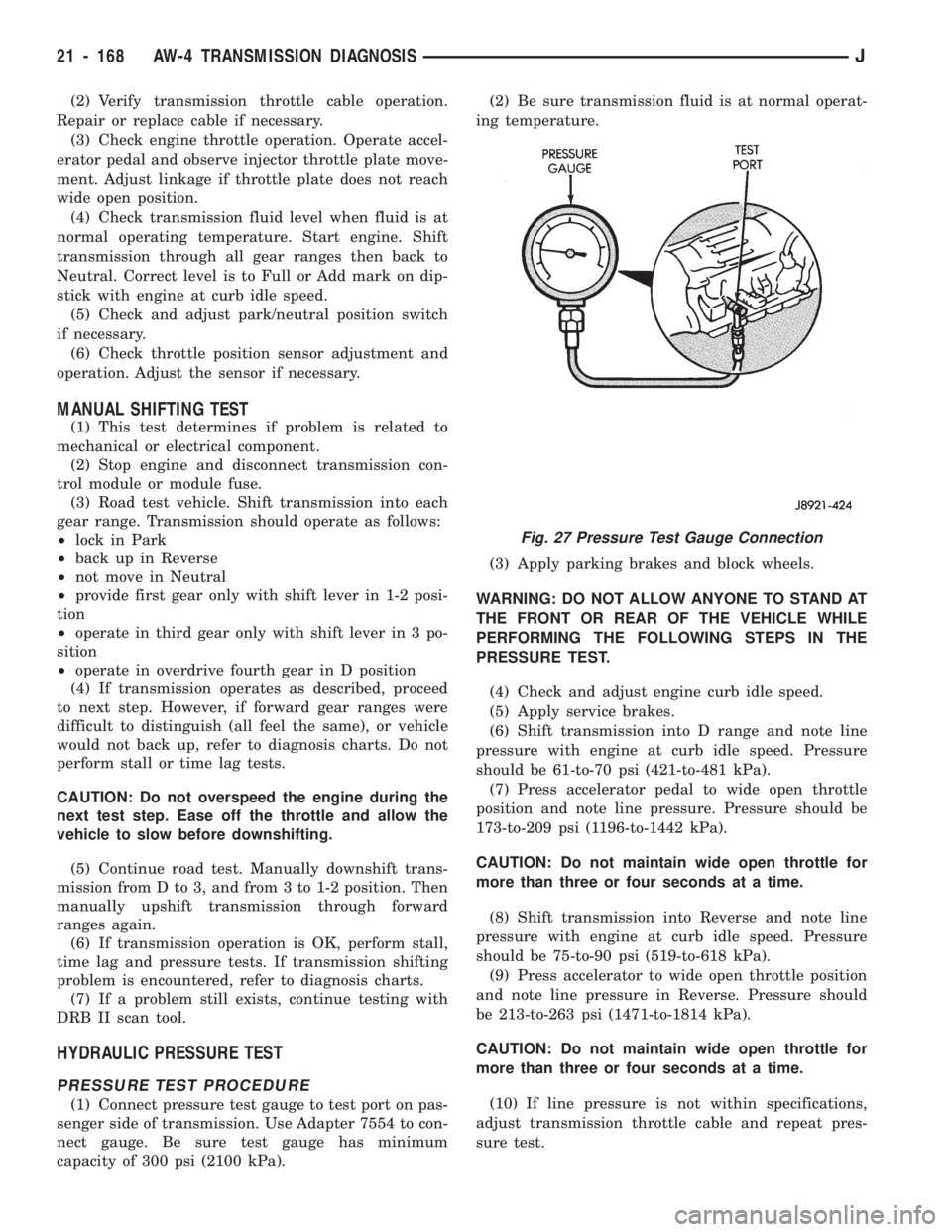
(1) Connect pressure test gauge to test port on pas-
senger side of transmission. Use Adapter 7554 to con-
nect gauge. Be sure test gauge has minimum
capacity of 300 psi (2100 kPa).(2) Be sure transmission fluid is at normal operat-
ing temperature.
(3) Apply parking brakes and block wheels.
WARNING: DO NOT ALLOW ANYONE TO STAND AT
THE FRONT OR REAR OF THE VEHICLE WHILE
PERFORMING THE FOLLOWING STEPS IN THE
PRESSURE TEST.
(4) Check and adjust engine curb idle speed.
(5) Apply service brakes.
(6) Shift transmission into D range and note line
pressure with engine at curb idle speed. Pressure
should be 61-to-70 psi (421-to-481 kPa).
(7) Press accelerator pedal to wide open throttle
position and note line pressure. Pressure should be
173-to-209 psi (1196-to-1442 kPa).
CAUTION: Do not maintain wide open throttle for
more than three or four seconds at a time.
(8) Shift transmission into Reverse and note line
pressure with engine at curb idle speed. Pressure
should be 75-to-90 psi (519-to-618 kPa).
(9) Press accelerator to wide open throttle position
and note line pressure in Reverse. Pressure should
be 213-to-263 psi (1471-to-1814 kPa).
CAUTION: Do not maintain wide open throttle for
more than three or four seconds at a time.
(10) If line pressure is not within specifications,
adjust transmission throttle cable and repeat pres-
sure test.
Fig. 27 Pressure Test Gauge Connection
21 - 168 AW-4 TRANSMISSION DIAGNOSISJ
Page 1280 of 1784
PRESSURE TEST ANALYSIS
If pressures in D and Reverse are higher than
specified, check for the following:
²throttle cable loose, worn, binding or out of adjust-
ment
²throttle valve, downshift plug, throttle cam, or pri-
mary regulator valve are sticking, worn or damaged
If pressures in D and Reverse are lower than spec-
ified, check for following:
²throttle cable loose, worn, binding or out of adjust-
ment
²throttle valve, downshift plug, throttle cam stick-
ing, worn or damaged
²primary regulator valve sticking, worn, or dam-
aged
²oil pump gears or housing worn or damaged
²overdrive clutch worn or damaged
If pressures are low in D range only, check for fol-
lowing:
²forward clutch worn or damaged
²fluid leakage in D range circuit (component seal
and O-rings)
If pressures are low in Reverse only, check for fol-
lowing:
²shift cable and manual valve out of adjustment
²fluid leakage in reverse circuit (component seal
and O-rings)
²direct clutch worn or damaged
²first/reverse brake worn or damaged
TORQUE CONVERTER STALL TEST
Stall testing checks the holding ability of the trans-
mission clutches and brakes and of the torque con-
verter stator overrunning clutch.
(1) Be sure transmission fluid is at normal operat-
ing temperature.
(2) Connect tachometer to engine. Position tachom-
eter so it can be viewed from drivers seat.
(3) Apply parking brakes and block wheels.
(4) Apply and hold service brakes.
(5) Shift transfer case into 2H position. On models
with NP249 transfer case, leave transfer case in 4H
position.
(6) Start engine.
WARNING: DO NOT ALLOW ANYONE TO STAND AT
THE FRONT OR REAR OF THE VEHICLE DURING
THE TEST.
(7) Shift transmission into D range.
(8) Press accelerator pedal to wide open throttle
position and note maximum engine rpm. Stall speed
should be 2100 to 2400 rpm in D range.
CAUTION: Do not maintain wide open throttle for
more than 3-4 seconds at a time.(9) Release throttle and shift transmission into
Neutral. Allow transmission fluid to cool for 15-20
seconds.
(10) Shift transmission into Reverse.
(11) Press accelerator down to wide open throttle
position and note maximum engine rpm. Stall speed
should be 2100-to-2400 rpm in Reverse.
STALL SPEED TEST ANALYSIS
If engine rpm is lower than specified in D and Re-
verse, check for the following:
²engine output/performance insufficient
²stator overrunning clutch in torque converter not
holding if engine speed was 1500 rpm or less.
If stall speed in D range is higher than specified,
check for the following:
²line pressure low
²forward clutch slipping
²No. 2 one-way clutch not holding
²overdrive one-way clutch not holding
If stall speed in Reverse was higher than specified,
check for the following:
²line pressure low
²direct clutch slipping
²first/ reverse brake slipping
²overdrive one-way clutch not holding
If stall speeds were higher than specified in both D
and Reverse, check for the following:
²low fluid level
²line pressure low
²overdrive one-way clutch not holding
TIME LAG TEST
This test checks general condition of the overdrive
clutch, forward clutch, rear clutch and first/reverse
brake. Condition is indicated by the amount of time
required for clutch/brake engagement with the en-
gine at curb idle speed. Engagement time is mea-
sured for D and Reverse positions. A stop watch is
recommended for test accuracy.
TEST PROCEDURE
(1) Check and adjust transmission fluid level if
necessary.
(2) Bring transmission to normal operating tem-
perature.
(3) Apply parking brakes and turn off air condi-
tioning unit.
(4) Shift transfer case into 2H range. On models
with NP249 transfer case, leave transfer case in 4H
range.
(5) Start engine and check curb idle speed. Adjust
speed if necessary. Curb idle must be correct to en-
sure accurate test results.
(6) Shift transmission into Neutral and set stop
watch.
(7) During following test steps, start stop watch as
soon as shift lever reaches D and Reverse ranges.
JAW-4 TRANSMISSION DIAGNOSIS 21 - 169