1994 JEEP CHEROKEE warning
[x] Cancel search: warningPage 1524 of 1784
(6) Remove the key lock cylinder.
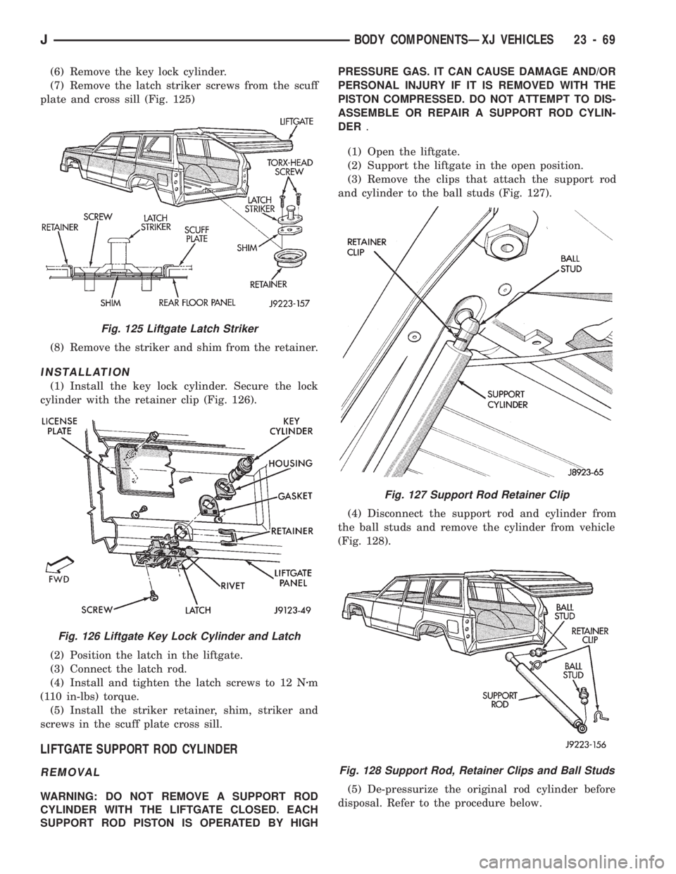
(7) Remove the latch striker screws from the scuff
plate and cross sill (Fig. 125)
(8) Remove the striker and shim from the retainer.
INSTALLATION
(1) Install the key lock cylinder. Secure the lock
cylinder with the retainer clip (Fig. 126).
(2) Position the latch in the liftgate.
(3) Connect the latch rod.
(4) Install and tighten the latch screws to 12 Nzm
(110 in-lbs) torque.
(5) Install the striker retainer, shim, striker and
screws in the scuff plate cross sill.
LIFTGATE SUPPORT ROD CYLINDER
REMOVAL
WARNING: DO NOT REMOVE A SUPPORT ROD
CYLINDER WITH THE LIFTGATE CLOSED. EACH
SUPPORT ROD PISTON IS OPERATED BY HIGHPRESSURE GAS. IT CAN CAUSE DAMAGE AND/OR
PERSONAL INJURY IF IT IS REMOVED WITH THE
PISTON COMPRESSED. DO NOT ATTEMPT TO DIS-
ASSEMBLE OR REPAIR A SUPPORT ROD CYLIN-
DER.
(1) Open the liftgate.
(2) Support the liftgate in the open position.
(3) Remove the clips that attach the support rod
and cylinder to the ball studs (Fig. 127).
(4) Disconnect the support rod and cylinder from
the ball studs and remove the cylinder from vehicle
(Fig. 128).
(5) De-pressurize the original rod cylinder before
disposal. Refer to the procedure below.
Fig. 127 Support Rod Retainer Clip
Fig. 128 Support Rod, Retainer Clips and Ball Studs
Fig. 125 Liftgate Latch Striker
Fig. 126 Liftgate Key Lock Cylinder and Latch
JBODY COMPONENTSÐXJ VEHICLES 23 - 69
Page 1525 of 1784
INSTALLATION
(1) Connect the replacement support rod and cylin-
der to the ball studs.
(2) Secure the support rod and cylinder to the ball
studs with the retainer clips.
(3) Remove the support from the liftgate and test
the operation of the support rod.
LIFTGATE SUPPORT ROD CYLINDER DISPOSAL
WARNING: SAFETY GOGGLES MUST BE WORN
DURING THE DISPOSAL PROCEDURE. THE HIGH
PRESSURE GAS CHARGE IN THE SUPPORT ROD
CYLINDERS WILL BE RELEASED DURING THE
PROCEDURE.
(1) Remove the support rod cylinder(s) from the
liftgate.
(2) Position the support rod cylinder horizontally
in a vise and clamp the cylinder securely.
(3) Wrap the cylinder with 4-5 layers of shop tow-
els.
(4) Measure 1 and 1/2 inches inward from the end
of the cylinder. Mark this location on the towels with
chalk. The cylinder will be punctured at this location
to release the gas charge.
(5) Use a punch and hammer to puncture cylinder.
Force the punch through towels and into the cylinder
with a hammer. Continue striking the punch until
the gas begins to escapebut do not remove the
punch.
(6) Hold the towels and punch in position until all
the gas has escaped. Complete de-pressurization will
require about 4 to 10 seconds. After all the gas has
escaped, slowly remove the punch.
(7) Hold a towel over the hole in cylinder and press
the support rod piston all the way into the cylinder
to purge remaining oil.
(8) Remove the support rod cylinder from the vise
and discard it.
(9) If both support rod cylinders are being re-
placed, repeat this procedure for the remaining cylin-
der.
LIFTGATE SUPPORT ROD BALL STUD
REPLACEMENT
REMOVAL
(1) Open the liftgate.
(2) Support the liftgate in the open position.
(3) Remove the retainer clip that attaches the sup-
port rod and cylinder to the ball stud.
(4) Disconnect the support rod from the ball stud.
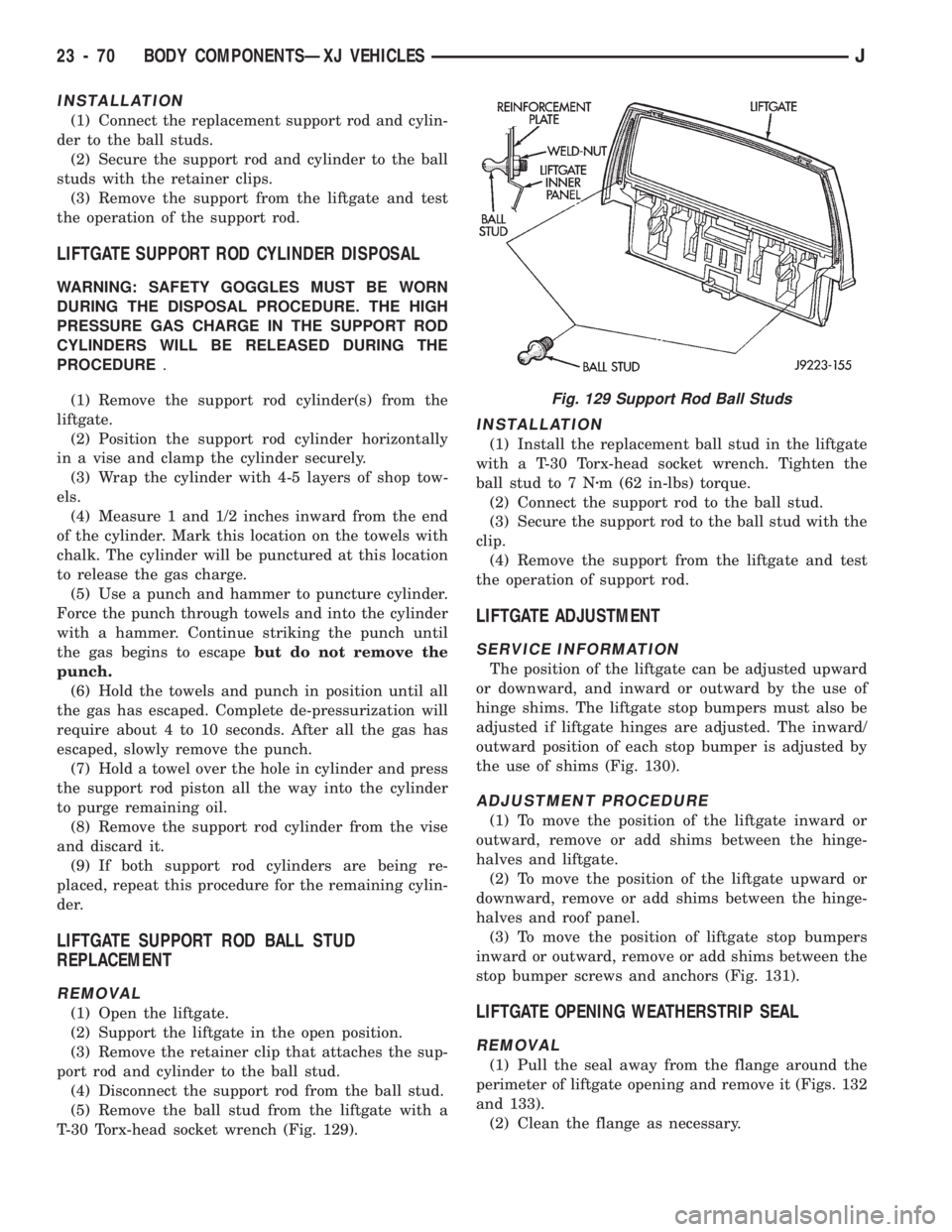
(5) Remove the ball stud from the liftgate with a
T-30 Torx-head socket wrench (Fig. 129).
INSTALLATION
(1) Install the replacement ball stud in the liftgate
with a T-30 Torx-head socket wrench. Tighten the
ball stud to 7 Nzm (62 in-lbs) torque.
(2) Connect the support rod to the ball stud.
(3) Secure the support rod to the ball stud with the
clip.
(4) Remove the support from the liftgate and test
the operation of support rod.
LIFTGATE ADJUSTMENT
SERVICE INFORMATION
The position of the liftgate can be adjusted upward
or downward, and inward or outward by the use of
hinge shims. The liftgate stop bumpers must also be
adjusted if liftgate hinges are adjusted. The inward/
outward position of each stop bumper is adjusted by
the use of shims (Fig. 130).
ADJUSTMENT PROCEDURE
(1) To move the position of the liftgate inward or
outward, remove or add shims between the hinge-
halves and liftgate.
(2) To move the position of the liftgate upward or
downward, remove or add shims between the hinge-
halves and roof panel.
(3) To move the position of liftgate stop bumpers
inward or outward, remove or add shims between the
stop bumper screws and anchors (Fig. 131).
LIFTGATE OPENING WEATHERSTRIP SEAL
REMOVAL
(1) Pull the seal away from the flange around the
perimeter of liftgate opening and remove it (Figs. 132
and 133).
(2) Clean the flange as necessary.
Fig. 129 Support Rod Ball Studs
23 - 70 BODY COMPONENTSÐXJ VEHICLESJ
Page 1530 of 1784
INTERIOR REARVIEW MIRROR SUPPORT
BRACKET REPLACEMENT
PREPARATION
(1) Mark reference lines for the mirror support
bracket on the outside of windshield glass with a wax
pencil.
(2) If the vinyl pad remained on the windshield
glass, soften and remove it with a heat gun.
(3) Clean the support bracket surface area on the
glass. Use a mild abrasive cleaning powder on a cloth
saturated with isopropyl (rubbing) alcohol.
(4) Lightly sand the contact surface on the support
bracket with fine grit sandpaper. Wipe bracket con-
tact surface clean with a paper towel and alcohol.
INSTALLATION
(1) Apply adhesive to the act surface on the sup-
port bracket according as follows:
²crush the vial in the plastic housing of the accel-
erator to saturate the felt applicator;
²remove the paper sleeve;
²apply a generous amount of accelerator to the con-
tact surface on the mirror support bracket;
²do not touch the support bracket contact surface
after the accelerator has been applied.
²allow the accelerator to dry for at least five min-
utes; and
(2) Apply accelerator to the support bracket con-
tact surface on the windshield glass. Allow the accel-
erator to dry for one minute.
(3) Install the mirror bracket on the windshield
glass follows:
²apply one drop of adhesive at the center of support
bracket contact surface on windshield glass;
²immediately apply an even coat of adhesive to the
contact surface on the support bracket;
²align the support bracket with the position refer-
ence lines on the windshield glass, then
²press and hold the support bracket in-place for at
least one minute.
Ensure that the mirror support bracket is
correctly aligned because the adhesive will
cure rapidly.
(4) Allow the adhesive to cure for 8-10 minutes,
then remove any residue adhesive with an alcohol-
dampened cloth.
(5) Allow the adhesive to cure for an additional
8-10 minutes before installing the mirror base on the
support bracket.
WINDSHIELD SERVICE INFORMATION
URETHANE ADHESIVE BONDING
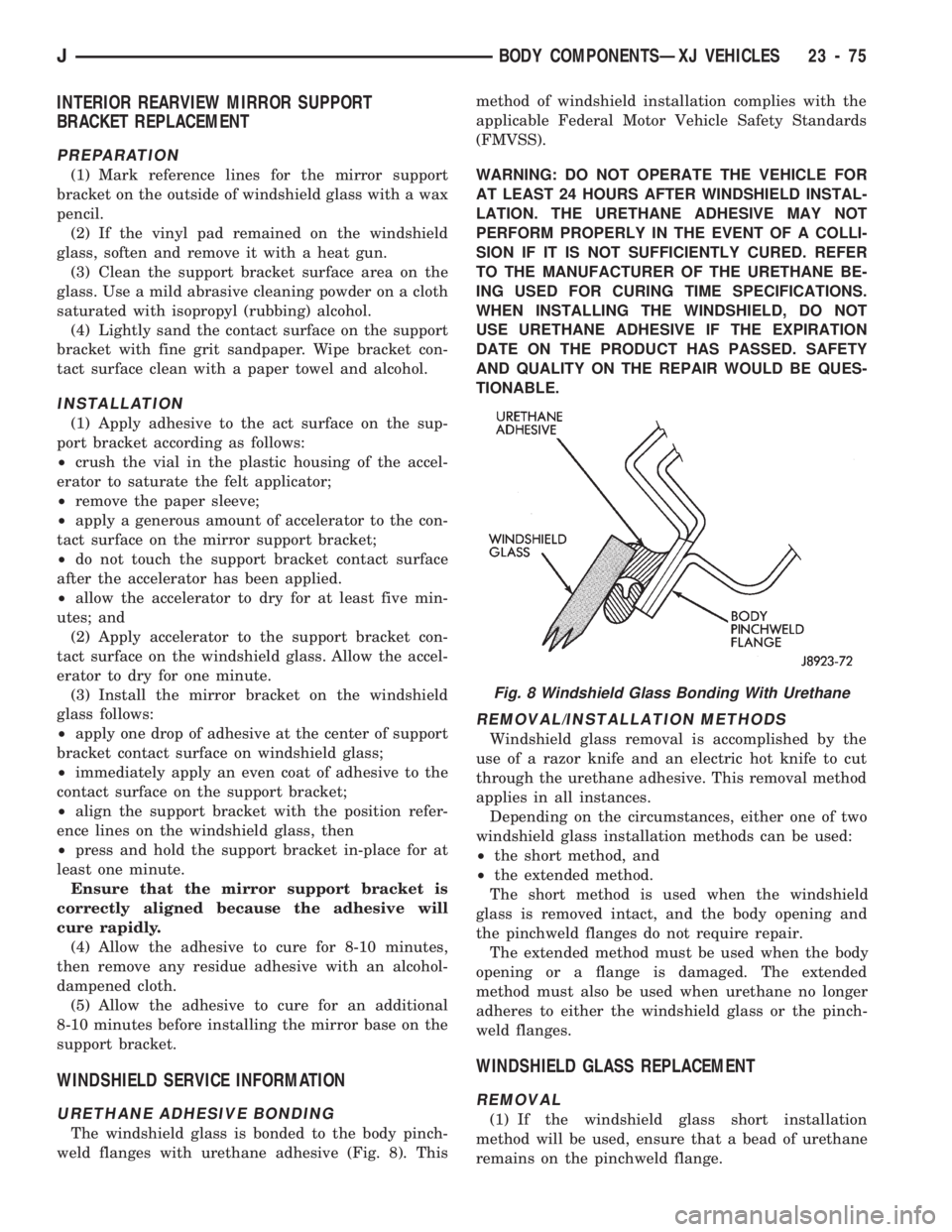
The windshield glass is bonded to the body pinch-
weld flanges with urethane adhesive (Fig. 8). Thismethod of windshield installation complies with the
applicable Federal Motor Vehicle Safety Standards
(FMVSS).
WARNING: DO NOT OPERATE THE VEHICLE FOR
AT LEAST 24 HOURS AFTER WINDSHIELD INSTAL-
LATION. THE URETHANE ADHESIVE MAY NOT
PERFORM PROPERLY IN THE EVENT OF A COLLI-
SION IF IT IS NOT SUFFICIENTLY CURED. REFER
TO THE MANUFACTURER OF THE URETHANE BE-
ING USED FOR CURING TIME SPECIFICATIONS.
WHEN INSTALLING THE WINDSHIELD, DO NOT
USE URETHANE ADHESIVE IF THE EXPIRATION
DATE ON THE PRODUCT HAS PASSED. SAFETY
AND QUALITY ON THE REPAIR WOULD BE QUES-
TIONABLE.
REMOVAL/INSTALLATION METHODS
Windshield glass removal is accomplished by the
use of a razor knife and an electric hot knife to cut
through the urethane adhesive. This removal method
applies in all instances.
Depending on the circumstances, either one of two
windshield glass installation methods can be used:
²the short method, and
²the extended method.
The short method is used when the windshield
glass is removed intact, and the body opening and
the pinchweld flanges do not require repair.
The extended method must be used when the body
opening or a flange is damaged. The extended
method must also be used when urethane no longer
adheres to either the windshield glass or the pinch-
weld flanges.
WINDSHIELD GLASS REPLACEMENT
REMOVAL
(1) If the windshield glass short installation
method will be used, ensure that a bead of urethane
remains on the pinchweld flange.
Fig. 8 Windshield Glass Bonding With Urethane
JBODY COMPONENTSÐXJ VEHICLES 23 - 75
Page 1609 of 1784
The following equipment and material are neces-
sary for body stripe/decal removal and installation:
²a commercial tape stripe/decal removal solution;
²a commercial adhesive removal solution;
²liquid dish detergent (for the wetting solution);
²a mixture of wetting solution;
²a commercial wax and silicone removal solution;
²isopropyl (rubbing) alcohol;
²a small squeegee (plastic or hard rubber);
²a water bucket and sponge;
²clean wiping rags or paper towels;
²a heat gun (or infra-red heat bulb);
²a wax pencil;
²a sharp knife, single edge razor blade or X-acto
knife;
²a pair of scissors; and
²a needle or pin.
A wetting solution assures a better bond between
the painted surface of the body and the tape stripe/
decal. Prepare a supply of wetting solution by mixing
two or three teaspoons of dish detergent with 1 gal-
lon of water.Do not use soap.
Too much detergent will reduce the effective-
ness of the mixture.
REMOVAL
The key to successful tape stripe/decal re-
moval is to apply heat to area and slowly peel
stripe/decal from panel.
(1) Clean the repaired surface, adjacent panels and
door openings as necessary.
(2) Start at one end of the tape stripe/decal and
apply heat with a heat gun. Slowly peel the stripe/
decal from the panel by pulling it back.Do not pull
the tape stripe/decal outward from the panel.
WARNING: USE THE TAPE STRIPE/DECAL RE-
MOVAL SOLUTION IN A WELL-VENTILATED AREA
ONLY.
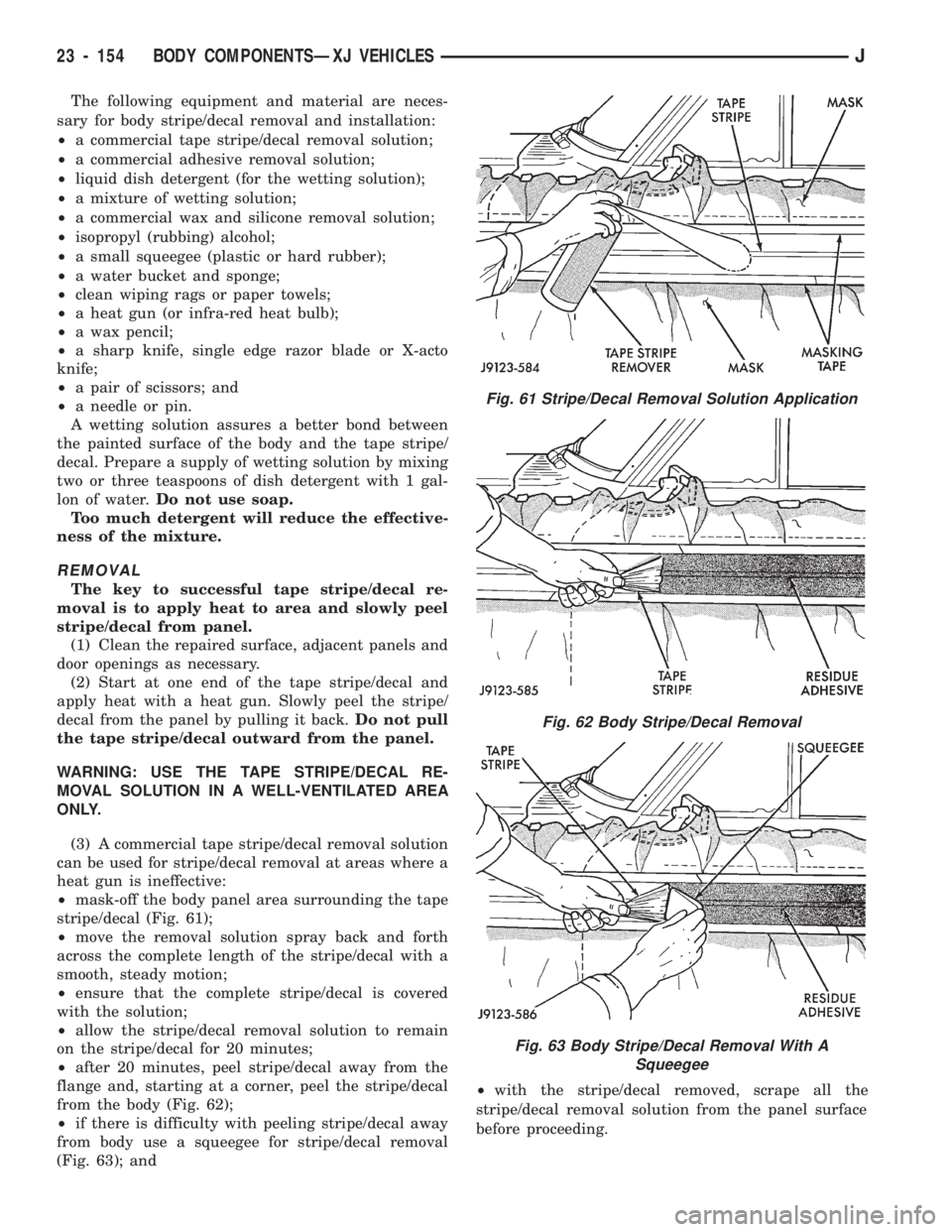
(3) A commercial tape stripe/decal removal solution
can be used for stripe/decal removal at areas where a
heat gun is ineffective:
²mask-off the body panel area surrounding the tape
stripe/decal (Fig. 61);
²move the removal solution spray back and forth
across the complete length of the stripe/decal with a
smooth, steady motion;
²ensure that the complete stripe/decal is covered
with the solution;
²allow the stripe/decal removal solution to remain
on the stripe/decal for 20 minutes;
²after 20 minutes, peel stripe/decal away from the
flange and, starting at a corner, peel the stripe/decal
from the body (Fig. 62);
²if there is difficulty with peeling stripe/decal away
from body use a squeegee for stripe/decal removal
(Fig. 63); and²with the stripe/decal removed, scrape all the
stripe/decal removal solution from the panel surface
before proceeding.
Fig. 61 Stripe/Decal Removal Solution Application
Fig. 62 Body Stripe/Decal Removal
Fig. 63 Body Stripe/Decal Removal With A
Squeegee
23 - 154 BODY COMPONENTSÐXJ VEHICLESJ
Page 1610 of 1784
WARNING: USE THE ADHESIVE REMOVAL SOLU-
TION IN A WELL-VENTILATED AREA ONLY.
(4) After the stripe/decal is removed, remove any
adhesive remaining on body with a removal solution.
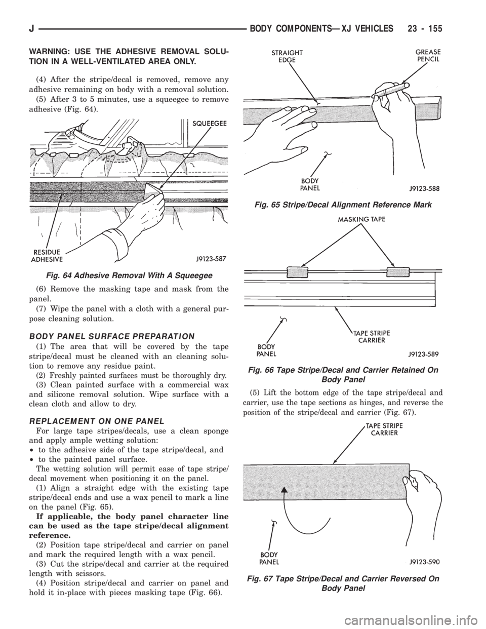
(5) After 3 to 5 minutes, use a squeegee to remove
adhesive (Fig. 64).
(6) Remove the masking tape and mask from the
panel.
(7) Wipe the panel with a cloth with a general pur-
pose cleaning solution.
BODY PANEL SURFACE PREPARATION
(1) The area that will be covered by the tape
stripe/decal must be cleaned with an cleaning solu-
tion to remove any residue paint.
(2) Freshly painted surfaces must be thoroughly dry.
(3) Clean painted surface with a commercial wax
and silicone removal solution. Wipe surface with a
clean cloth and allow to dry.
REPLACEMENT ON ONE PANEL
For large tape stripes/decals, use a clean sponge
and apply ample wetting solution:
²to the adhesive side of the tape stripe/decal, and
²to the painted panel surface.
The wetting solution will permit ease of tape stripe/
decal movement when positioning it on the panel.
(1) Align a straight edge with the existing tape
stripe/decal ends and use a wax pencil to mark a line
on the panel (Fig. 65).
If applicable, the body panel character line
can be used as the tape stripe/decal alignment
reference.
(2) Position tape stripe/decal and carrier on panel
and mark the required length with a wax pencil.
(3) Cut the stripe/decal and carrier at the required
length with scissors.
(4) Position stripe/decal and carrier on panel and
hold it in-place with pieces masking tape (Fig. 66).
(5) Lift the bottom edge of the tape stripe/decal and
carrier, use the tape sections as hinges, and reverse the
position of the stripe/decal and carrier (Fig. 67).
Fig. 65 Stripe/Decal Alignment Reference Mark
Fig. 66 Tape Stripe/Decal and Carrier Retained On
Body Panel
Fig. 67 Tape Stripe/Decal and Carrier Reversed On
Body Panel
Fig. 64 Adhesive Removal With A Squeegee
JBODY COMPONENTSÐXJ VEHICLES 23 - 155
Page 1617 of 1784
INSTALLATION
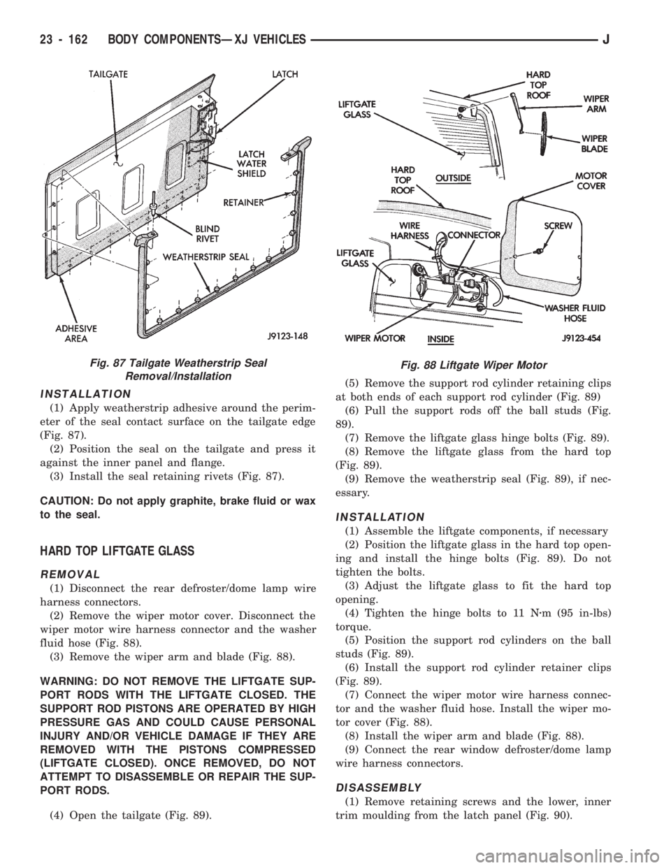
(1) Apply weatherstrip adhesive around the perim-
eter of the seal contact surface on the tailgate edge
(Fig. 87).
(2) Position the seal on the tailgate and press it
against the inner panel and flange.
(3) Install the seal retaining rivets (Fig. 87).
CAUTION: Do not apply graphite, brake fluid or wax
to the seal.
HARD TOP LIFTGATE GLASS
REMOVAL
(1) Disconnect the rear defroster/dome lamp wire
harness connectors.
(2) Remove the wiper motor cover. Disconnect the
wiper motor wire harness connector and the washer
fluid hose (Fig. 88).
(3) Remove the wiper arm and blade (Fig. 88).
WARNING: DO NOT REMOVE THE LIFTGATE SUP-
PORT RODS WITH THE LIFTGATE CLOSED. THE
SUPPORT ROD PISTONS ARE OPERATED BY HIGH
PRESSURE GAS AND COULD CAUSE PERSONAL
INJURY AND/OR VEHICLE DAMAGE IF THEY ARE
REMOVED WITH THE PISTONS COMPRESSED
(LIFTGATE CLOSED). ONCE REMOVED, DO NOT
ATTEMPT TO DISASSEMBLE OR REPAIR THE SUP-
PORT RODS.
(4) Open the tailgate (Fig. 89).(5) Remove the support rod cylinder retaining clips
at both ends of each support rod cylinder (Fig. 89)
(6) Pull the support rods off the ball studs (Fig.
89).
(7) Remove the liftgate glass hinge bolts (Fig. 89).
(8) Remove the liftgate glass from the hard top
(Fig. 89).
(9) Remove the weatherstrip seal (Fig. 89), if nec-
essary.
INSTALLATION
(1) Assemble the liftgate components, if necessary
(2) Position the liftgate glass in the hard top open-
ing and install the hinge bolts (Fig. 89). Do not
tighten the bolts.
(3) Adjust the liftgate glass to fit the hard top
opening.
(4) Tighten the hinge bolts to 11 Nzm (95 in-lbs)
torque.
(5) Position the support rod cylinders on the ball
studs (Fig. 89).
(6) Install the support rod cylinder retainer clips
(Fig. 89).
(7) Connect the wiper motor wire harness connec-
tor and the washer fluid hose. Install the wiper mo-
tor cover (Fig. 88).
(8) Install the wiper arm and blade (Fig. 88).
(9) Connect the rear window defroster/dome lamp
wire harness connectors.
DISASSEMBLY
(1) Remove retaining screws and the lower, inner
trim moulding from the latch panel (Fig. 90).
Fig. 87 Tailgate Weatherstrip Seal
Removal/InstallationFig. 88 Liftgate Wiper Motor
23 - 162 BODY COMPONENTSÐXJ VEHICLESJ
Page 1646 of 1784
INSTRUMENT CLUSTER BEZEL
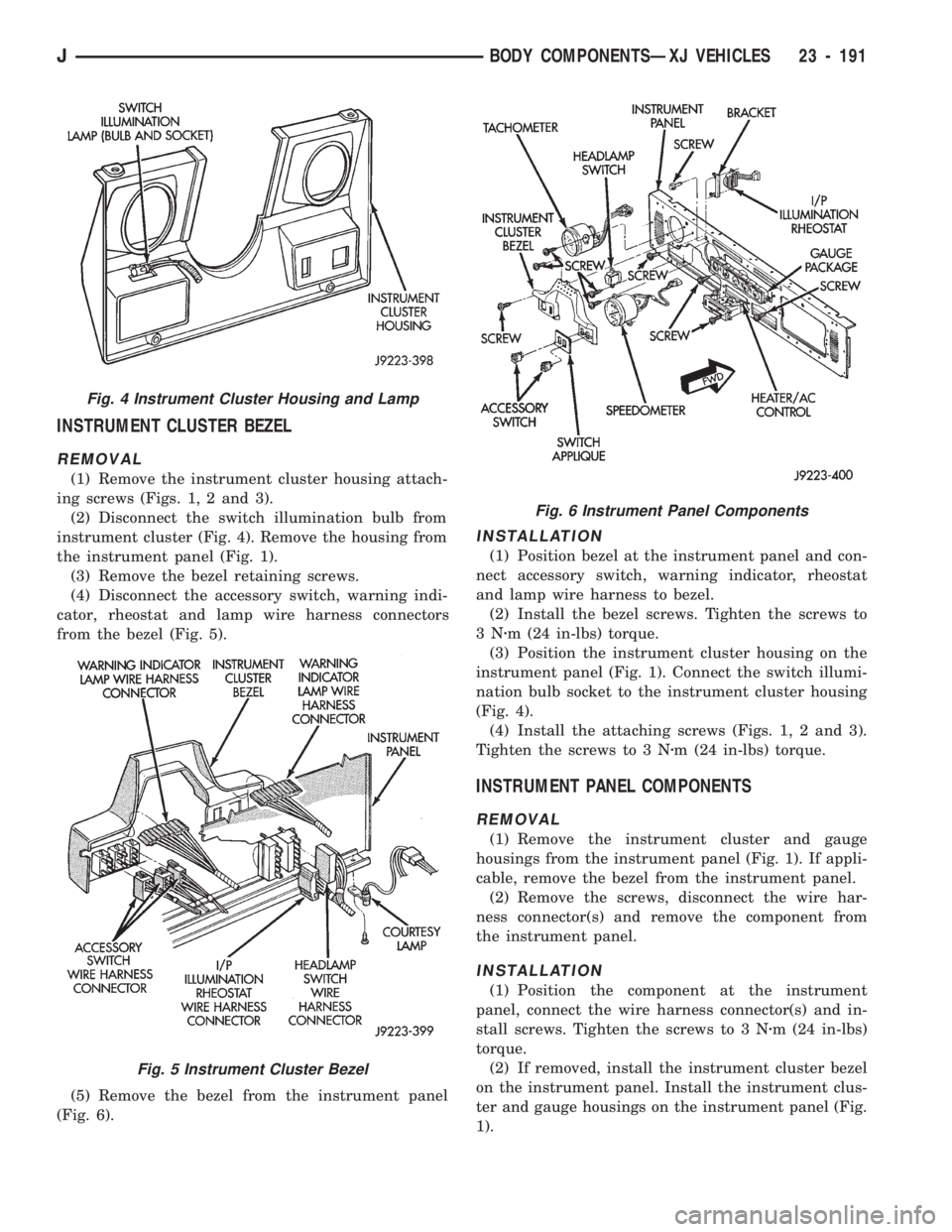
REMOVAL
(1) Remove the instrument cluster housing attach-
ing screws (Figs. 1, 2 and 3).
(2) Disconnect the switch illumination bulb from
instrument cluster (Fig. 4). Remove the housing from
the instrument panel (Fig. 1).
(3) Remove the bezel retaining screws.
(4) Disconnect the accessory switch, warning indi-
cator, rheostat and lamp wire harness connectors
from the bezel (Fig. 5).
(5) Remove the bezel from the instrument panel
(Fig. 6).
INSTALLATION
(1) Position bezel at the instrument panel and con-
nect accessory switch, warning indicator, rheostat
and lamp wire harness to bezel.
(2) Install the bezel screws. Tighten the screws to
3Nzm (24 in-lbs) torque.
(3) Position the instrument cluster housing on the
instrument panel (Fig. 1). Connect the switch illumi-
nation bulb socket to the instrument cluster housing
(Fig. 4).
(4) Install the attaching screws (Figs. 1, 2 and 3).
Tighten the screws to 3 Nzm (24 in-lbs) torque.
INSTRUMENT PANEL COMPONENTS
REMOVAL
(1) Remove the instrument cluster and gauge
housings from the instrument panel (Fig. 1). If appli-
cable, remove the bezel from the instrument panel.
(2) Remove the screws, disconnect the wire har-
ness connector(s) and remove the component from
the instrument panel.
INSTALLATION
(1) Position the component at the instrument
panel, connect the wire harness connector(s) and in-
stall screws. Tighten the screws to 3 Nzm (24 in-lbs)
torque.
(2) If removed, install the instrument cluster bezel
on the instrument panel. Install the instrument clus-
ter and gauge housings on the instrument panel (Fig.
1).
Fig. 4 Instrument Cluster Housing and Lamp
Fig. 5 Instrument Cluster Bezel
Fig. 6 Instrument Panel Components
JBODY COMPONENTSÐXJ VEHICLES 23 - 191
Page 1664 of 1784
HEATING AND AIR CONDITIONING
CONTENTS
page page
CLIMATE CONTROL SYSTEMÐXJ VEHICLES . 22
CLIMATE CONTROL SYSTEMÐYJ VEHICLES . 37
COMPRESSOR OVERHAUL............... 17
GENERAL INFORMATION.................. 1SERVICE DIAGNOSISÐELECTRICAL........ 14
SERVICE DIAGNOSISÐMECHANICAL........ 8
TORQUE SPECIFICATIONS................ 45
GENERAL INFORMATION
INDEX
page page
A/C Operation............................ 1
Compressor Oil Level...................... 6
Pressure Gauge and Manifold Assembly........ 2
Refrigerant (R-12)......................... 1
Service Precautions........................ 2Service Valves........................... 3
System Charge........................... 5
System Discharge......................... 4
System Evacuation........................ 4
A/C OPERATION
The compressor increases the pressure and temper-
ature of the refrigerant. The heated refrigerant vapor
is then pumped into the condenser where it cools by
the air passing over the condenser fins. As the refrig-
erant cools in the condenser, it condenses into a liq-
uid. Still under high pressure, the liquid refrigerant
passes into the receiver. The receiver acts as a reser-
voir to furnish refrigerant to the expansion (H) valve
at all times. From the receiver, the high pressure liq-
uid refrigerant passes to the expansion (H) valve.
The expansion (H) valve meters refrigerant into the
evaporator where a low pressure is maintained by
the suction side of the compressor. As it enters the
evaporator, the refrigerant immediately begins to
boil by absorbing heat from the air passing over the
evaporator core. Having given up its heat to boil the
refrigerant, the air is cooled and passes into the pas-
senger compartment of the vehicle. From the evapo-
rator the vaporized refrigerant is drawn back to the
compressor to repeat the cycle.
REFRIGERANT (R-12)
It is illegal to release R-12 into the atmosphere.
SAFETY PRECAUTIONS
WARNING: EXTREME CARE MUST BE TAKEN TO
PREVENT ANY LIQUID REFRIGERANT FROM COM-
ING IN CONTACT WITH THE SKIN AND ESPE-
CIALLY THE EYES. ALWAYS WEAR SAFETYGOGGLES WHEN SERVICING ANY PART OF THE
REFRIGERANT SYSTEM. IF EYE CONTACT IS
MADE, APPLY A FEW DROPS OF MINERAL OIL TO
THE EYES AND FLUSH WITH WATER FOR SEV-
ERAL MINUTES. SEEK MEDICAL ATTENTION IMME-
DIATELY.
The refrigerant used in the air conditioner system
is Refrigerant-12 (R-12). R-12 is nonexplosive, non-
flammable, non-corrosive, has practically no odor and
is heavier than air. Although it is classified as a safe
refrigerant, certain precautions must be observed to
protect the parts involved and the person who is
working on the unit. Liquid R-12, at normal atmo-
sphere pressures and temperatures, evaporates so
quickly that it has the tendency to freeze anything it
contacts.
WARNING: TO AVOID A DANGEROUS EXPLOSION,
NEVER WELD OR STEAM CLEAN NEAR AIR CON-
DITIONING LINES OR COMPONENTS. DO NOT
HEAT R-12 ABOVE 52ÉC (125ÉF).
The R-12 in the system is always under pressure.
Because the system is tightly sealed, heat applied to
any part could cause this pressure to build up exces-
sively.
JHEATING AND AIR CONDITIONING 24 - 1