1994 JEEP CHEROKEE engine
[x] Cancel search: enginePage 259 of 1784
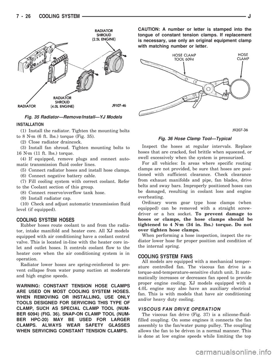
INSTALLATION
(1) Install the radiator. Tighten the mounting bolts
to8Nzm (6 ft. lbs.) torque (Fig. 35).
(2) Close radiator draincock.
(3) Install fan shroud. Tighten mounting bolts to
16 Nzm (11 ft. lbs.) torque.
(4) If equipped, remove plugs and connect auto-
matic transmission fluid cooler lines.
(5) Connect radiator hoses and install hose clamps.
(6) Connect negative battery cable.
(7) Fill cooling system with correct coolant. Refer
to the Coolant section of this group.
(8) Connect reserve/overflow tank hose.
(9) Install radiator cap.
(10) Check and adjust automatic transmission fluid
level (if equipped).
COOLING SYSTEM HOSES
Rubber hoses route coolant to and from the radia-
tor, intake manifold and heater core. All XJ models
equipped with air conditioning have a coolant control
valve. This is located in-line with the heater core in-
let and outlet hoses. It controls coolant flow to the
heater core when the air conditioning system is in
operation.
Radiator lower hoses are spring-reinforced to pre-
vent collapse from water pump suction at moderate
and high engine speeds.
WARNING: CONSTANT TENSION HOSE CLAMPS
ARE USED ON MOST COOLING SYSTEM HOSES.
WHEN REMOVING OR INSTALLING, USE ONLY
TOOLS DESIGNED FOR SERVICING THIS TYPE OF
CLAMP, SUCH AS SPECIAL CLAMP TOOL (NUM-
BER 6094) (FIG. 36). SNAP-ON CLAMP TOOL (NUM-
BER HPC-20) MAY BE USED FOR LARGER
CLAMPS. ALWAYS WEAR SAFETY GLASSES
WHEN SERVICING CONSTANT TENSION CLAMPS.CAUTION: A number or letter is stamped into the
tongue of constant tension clamps. If replacement
is necessary, use only an original equipment clamp
with matching number or letter.
Inspect the hoses at regular intervals. Replace
hoses that are cracked, feel brittle when squeezed, or
swell excessively when the system is pressurized.
For all vehicles: In areas where specific routing
clamps are not provided, be sure that hoses are posi-
tioned with sufficient clearance. Check clearance
from exhaust manifolds and pipe, fan blades, drive
belts and sway bars. Improperly positioned hoses can
be damaged, resulting in coolant loss and engine
overheating.
Ordinary worm gear type hose clamps (when
equipped) can be removed with a straight screw-
driver or a hex socket.To prevent damage to
hoses or clamps, the hose clamps should be
tightened to 4 Nzm (34 in. lbs.) torque. Do not
over tighten hose clamps.
When performing a hose inspection, inspect the ra-
diator lower hose for proper position and condition of
the internal spring.
COOLING SYSTEM FANS
All models are equipped with a mechanical temper-
ature controlled fan. The viscous fan drive is a
torque-and-temperature-sensitive clutch unit. It auto-
matically increases or decreases fan speed to provide
proper engine cooling. XJ models equipped with a
4.0L engine may also have an auxiliary electrical
fan. This is with models that have air conditioning
and/or heavy duty cooling.
VISCOUS FAN DRIVE OPERATION
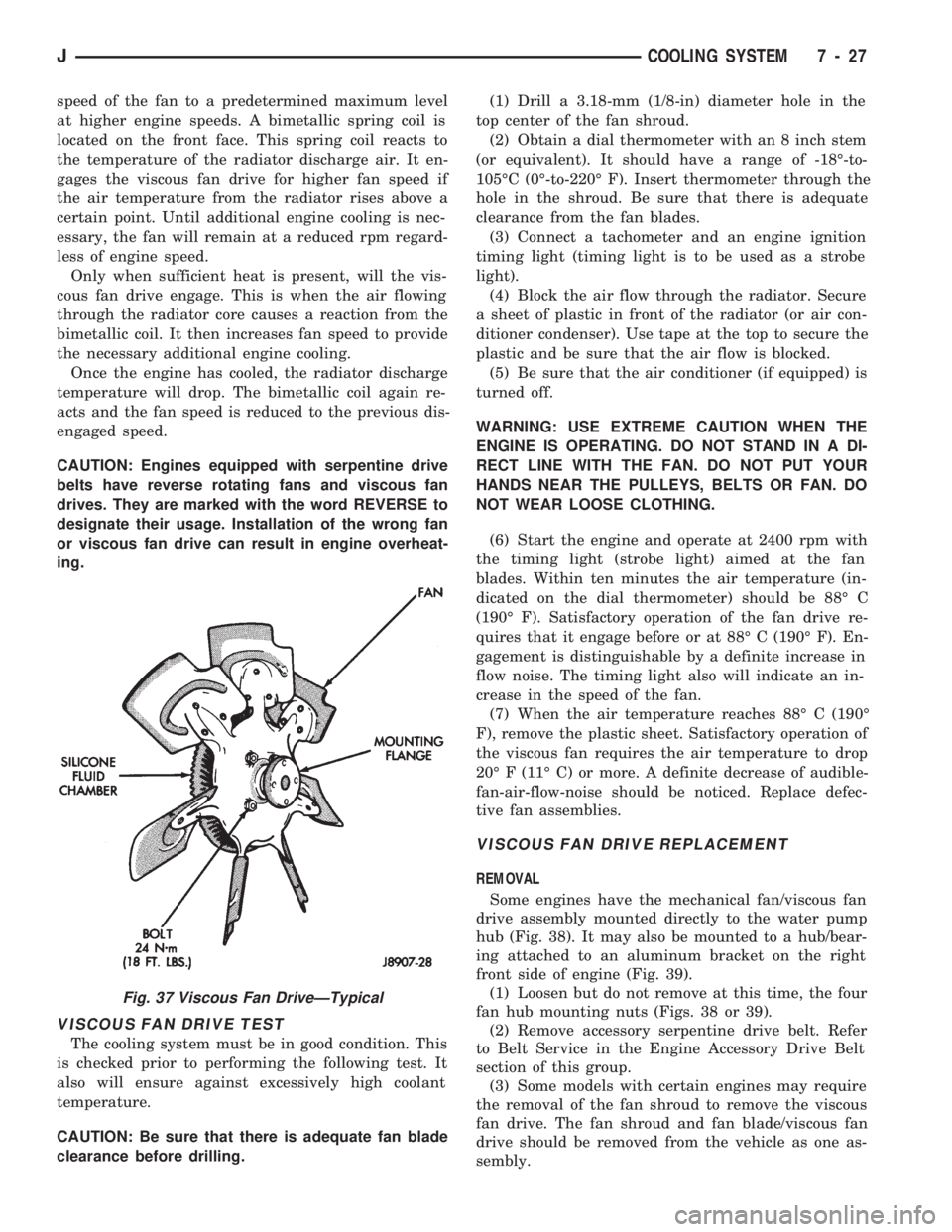
The viscous fan drive (Fig. 37) is a silicone-fluid-
filled coupling. On some engines it connects the fan
assembly to the fan/water pump pulley. The coupling
allows the fan to be driven in a normal manner. This
is done at low engine speeds while limiting the top
Fig. 35 RadiatorÐRemove/InstallÐYJ Models
Fig. 36 Hose Clamp ToolÐTypical
7 - 26 COOLING SYSTEMJ
Page 260 of 1784
speed of the fan to a predetermined maximum level
at higher engine speeds. A bimetallic spring coil is
located on the front face. This spring coil reacts to
the temperature of the radiator discharge air. It en-
gages the viscous fan drive for higher fan speed if
the air temperature from the radiator rises above a
certain point. Until additional engine cooling is nec-
essary, the fan will remain at a reduced rpm regard-
less of engine speed.
Only when sufficient heat is present, will the vis-
cous fan drive engage. This is when the air flowing
through the radiator core causes a reaction from the
bimetallic coil. It then increases fan speed to provide
the necessary additional engine cooling.
Once the engine has cooled, the radiator discharge
temperature will drop. The bimetallic coil again re-
acts and the fan speed is reduced to the previous dis-
engaged speed.
CAUTION: Engines equipped with serpentine drive
belts have reverse rotating fans and viscous fan
drives. They are marked with the word REVERSE to
designate their usage. Installation of the wrong fan
or viscous fan drive can result in engine overheat-
ing.
VISCOUS FAN DRIVE TEST
The cooling system must be in good condition. This
is checked prior to performing the following test. It
also will ensure against excessively high coolant
temperature.
CAUTION: Be sure that there is adequate fan blade
clearance before drilling.(1) Drill a 3.18-mm (1/8-in) diameter hole in the
top center of the fan shroud.
(2) Obtain a dial thermometer with an 8 inch stem
(or equivalent). It should have a range of -18É-to-
105ÉC (0É-to-220É F). Insert thermometer through the
hole in the shroud. Be sure that there is adequate
clearance from the fan blades.
(3) Connect a tachometer and an engine ignition
timing light (timing light is to be used as a strobe
light).
(4) Block the air flow through the radiator. Secure
a sheet of plastic in front of the radiator (or air con-
ditioner condenser). Use tape at the top to secure the
plastic and be sure that the air flow is blocked.
(5) Be sure that the air conditioner (if equipped) is
turned off.
WARNING: USE EXTREME CAUTION WHEN THE
ENGINE IS OPERATING. DO NOT STAND IN A DI-
RECT LINE WITH THE FAN. DO NOT PUT YOUR
HANDS NEAR THE PULLEYS, BELTS OR FAN. DO
NOT WEAR LOOSE CLOTHING.
(6) Start the engine and operate at 2400 rpm with
the timing light (strobe light) aimed at the fan
blades. Within ten minutes the air temperature (in-
dicated on the dial thermometer) should be 88É C
(190É F). Satisfactory operation of the fan drive re-
quires that it engage before or at 88É C (190É F). En-
gagement is distinguishable by a definite increase in
flow noise. The timing light also will indicate an in-
crease in the speed of the fan.
(7) When the air temperature reaches 88É C (190É
F), remove the plastic sheet. Satisfactory operation of
the viscous fan requires the air temperature to drop
20É F (11É C) or more. A definite decrease of audible-
fan-air-flow-noise should be noticed. Replace defec-
tive fan assemblies.
VISCOUS FAN DRIVE REPLACEMENT
REMOVAL
Some engines have the mechanical fan/viscous fan
drive assembly mounted directly to the water pump
hub (Fig. 38). It may also be mounted to a hub/bear-
ing attached to an aluminum bracket on the right
front side of engine (Fig. 39).
(1) Loosen but do not remove at this time, the four
fan hub mounting nuts (Figs. 38 or 39).
(2) Remove accessory serpentine drive belt. Refer
to Belt Service in the Engine Accessory Drive Belt
section of this group.
(3) Some models with certain engines may require
the removal of the fan shroud to remove the viscous
fan drive. The fan shroud and fan blade/viscous fan
drive should be removed from the vehicle as one as-
sembly.
Fig. 37 Viscous Fan DriveÐTypical
JCOOLING SYSTEM 7 - 27
Page 261 of 1784
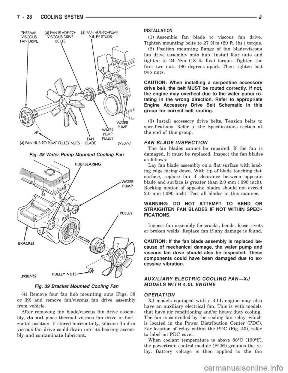
(4) Remove four fan hub mounting nuts (Figs. 38
or 39) and remove fan/viscous fan drive assembly
from vehicle.
After removing fan blade/viscous fan drive assem-
bly,do notplace thermal viscous fan drive in hori-
zontal position. If stored horizontally, silicone fluid in
viscous fan drive could drain into its bearing assem-
bly and contaminate lubricant.INSTALLATION
(1) Assemble fan blade to viscous fan drive.
Tighten mounting bolts to 27 Nzm (20 ft. lbs.) torque.
(2) Position mounting flange of fan blade/viscous
fan drive assembly onto hub. Install four nuts and
tighten to 24 Nzm (18 ft. lbs.) torque. Tighten the
first two nuts 180 degrees apart. Then tighten last
two nuts.
CAUTION: When installing a serpentine accessory
drive belt, the belt MUST be routed correctly. If not,
the engine may overheat due to the water pump ro-
tating in the wrong direction. Refer to appropriate
Engine Accessory Drive Belt Schematic in this
group for correct belt routing.
(3) Install accessory drive belts. Tension belts to
specifications. Refer to the Specifications section at
the end of this group.
FAN BLADE INSPECTION
The fan blades cannot be repaired. If the fan is
damaged, it must be replaced. Inspect the fan blades
as follows:
Lay fan blade assembly on a flat surface with lead-
ing edge facing down. With tip of blade touching flat
surface, replace fan if clearance between opposite
blade and surface is greater than 2.0 mm (.090 inch).
Rocking motion of opposite blades should not exceed
2.0 mm (.090 inch). Test all blades in this manner.
WARNING: DO NOT ATTEMPT TO BEND OR
STRAIGHTEN FAN BLADES IF NOT WITHIN SPECI-
FICATIONS.
Inspect fan assembly for cracks, bends, loose rivets
or broken welds. Replace fan if any damage is found.
CAUTION: If the fan blade assembly is replaced be-
cause of mechanical damage, the water pump and
viscous fan drive should also be inspected. These
components could have been damaged due to ex-
cessive vibration.
AUXILIARY ELECTRIC COOLING FANÐXJ
MODELS WITH 4.0L ENGINE
OPERATION
XJ models equipped with a 4.0L engine may also
have an auxiliary electrical fan. This is with models
that have air conditioning and/or heavy duty cooling.
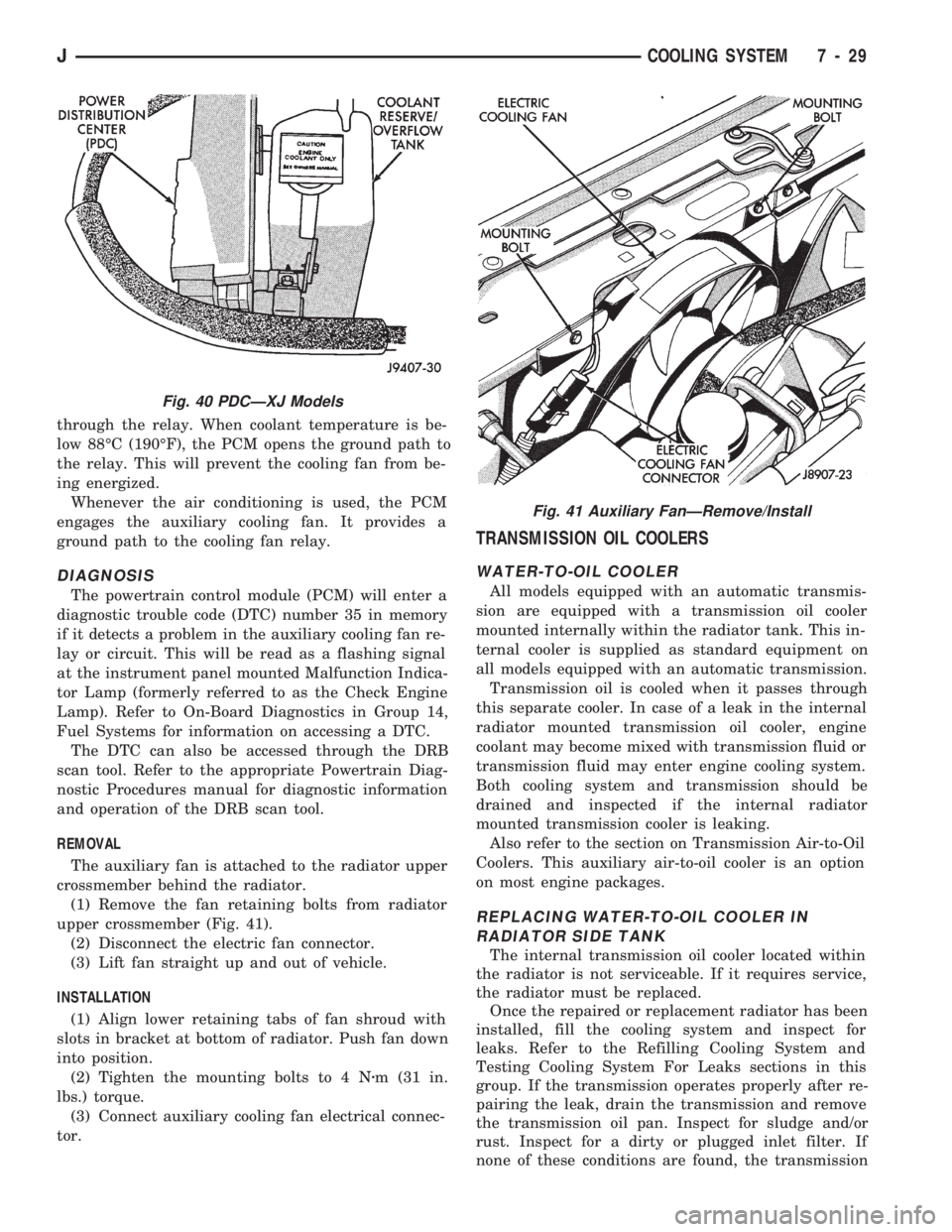
The fan is controlled by the cooling fan relay, which
is located in the Power Distribution Center (PDC).
For location of relay within the PDC (Fig. 40), refer
to label on PDC cover.
When coolant temperature is above 88ÉC (190ÉF),
the powertrain control module (PCM) grounds the re-
lay. Battery voltage is then applied to the fan
Fig. 38 Water Pump Mounted Cooling Fan
Fig. 39 Bracket Mounted Cooling Fan
7 - 28 COOLING SYSTEMJ
Page 262 of 1784
through the relay. When coolant temperature is be-
low 88ÉC (190ÉF), the PCM opens the ground path to
the relay. This will prevent the cooling fan from be-
ing energized.
Whenever the air conditioning is used, the PCM
engages the auxiliary cooling fan. It provides a
ground path to the cooling fan relay.
DIAGNOSIS
The powertrain control module (PCM) will enter a
diagnostic trouble code (DTC) number 35 in memory
if it detects a problem in the auxiliary cooling fan re-
lay or circuit. This will be read as a flashing signal
at the instrument panel mounted Malfunction Indica-
tor Lamp (formerly referred to as the Check Engine
Lamp). Refer to On-Board Diagnostics in Group 14,
Fuel Systems for information on accessing a DTC.
The DTC can also be accessed through the DRB
scan tool. Refer to the appropriate Powertrain Diag-
nostic Procedures manual for diagnostic information
and operation of the DRB scan tool.
REMOVAL
The auxiliary fan is attached to the radiator upper
crossmember behind the radiator.
(1) Remove the fan retaining bolts from radiator
upper crossmember (Fig. 41).
(2) Disconnect the electric fan connector.
(3) Lift fan straight up and out of vehicle.
INSTALLATION
(1) Align lower retaining tabs of fan shroud with
slots in bracket at bottom of radiator. Push fan down
into position.
(2) Tighten the mounting bolts to 4 Nzm (31 in.
lbs.) torque.
(3) Connect auxiliary cooling fan electrical connec-
tor.
TRANSMISSION OIL COOLERS
WATER-TO-OIL COOLER
All models equipped with an automatic transmis-
sion are equipped with a transmission oil cooler
mounted internally within the radiator tank. This in-
ternal cooler is supplied as standard equipment on
all models equipped with an automatic transmission.
Transmission oil is cooled when it passes through
this separate cooler. In case of a leak in the internal
radiator mounted transmission oil cooler, engine
coolant may become mixed with transmission fluid or
transmission fluid may enter engine cooling system.
Both cooling system and transmission should be
drained and inspected if the internal radiator
mounted transmission cooler is leaking.
Also refer to the section on Transmission Air-to-Oil
Coolers. This auxiliary air-to-oil cooler is an option
on most engine packages.
REPLACING WATER-TO-OIL COOLER IN
RADIATOR SIDE TANK
The internal transmission oil cooler located within
the radiator is not serviceable. If it requires service,
the radiator must be replaced.
Once the repaired or replacement radiator has been
installed, fill the cooling system and inspect for
leaks. Refer to the Refilling Cooling System and
Testing Cooling System For Leaks sections in this
group. If the transmission operates properly after re-
pairing the leak, drain the transmission and remove
the transmission oil pan. Inspect for sludge and/or
rust. Inspect for a dirty or plugged inlet filter. If
none of these conditions are found, the transmission
Fig. 40 PDCÐXJ Models
Fig. 41 Auxiliary FanÐRemove/Install
JCOOLING SYSTEM 7 - 29
Page 263 of 1784
and torque convertor may not require reconditioning.
Refer to Group 21 for automatic transmission servic-
ing.
AIR-TO-OIL COOLER
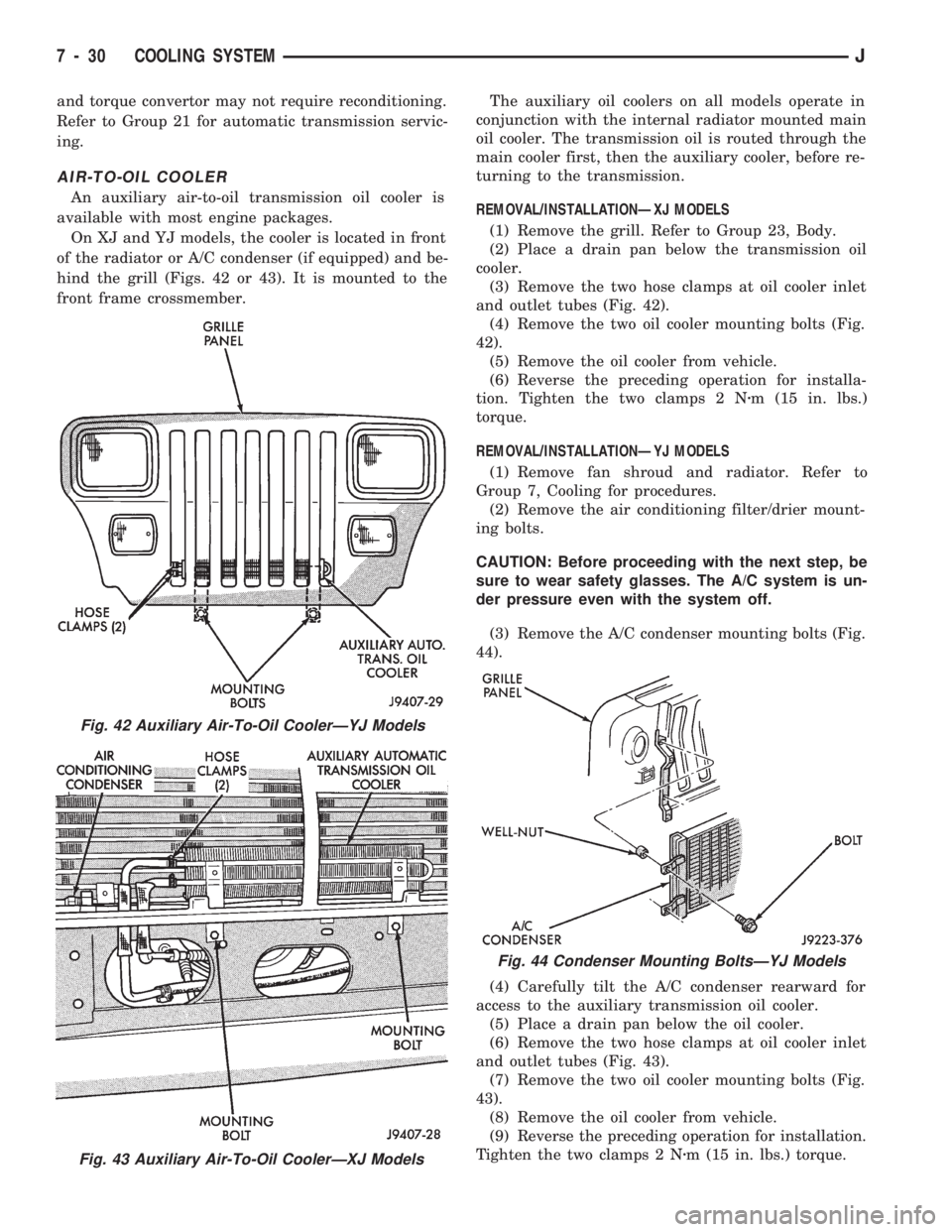
An auxiliary air-to-oil transmission oil cooler is
available with most engine packages.
On XJ and YJ models, the cooler is located in front
of the radiator or A/C condenser (if equipped) and be-
hind the grill (Figs. 42 or 43). It is mounted to the
front frame crossmember.The auxiliary oil coolers on all models operate in
conjunction with the internal radiator mounted main
oil cooler. The transmission oil is routed through the
main cooler first, then the auxiliary cooler, before re-
turning to the transmission.
REMOVAL/INSTALLATIONÐXJ MODELS
(1) Remove the grill. Refer to Group 23, Body.
(2) Place a drain pan below the transmission oil
cooler.
(3) Remove the two hose clamps at oil cooler inlet
and outlet tubes (Fig. 42).
(4) Remove the two oil cooler mounting bolts (Fig.
42).
(5) Remove the oil cooler from vehicle.
(6) Reverse the preceding operation for installa-
tion. Tighten the two clamps 2 Nzm (15 in. lbs.)
torque.
REMOVAL/INSTALLATIONÐYJ MODELS
(1) Remove fan shroud and radiator. Refer to
Group 7, Cooling for procedures.
(2) Remove the air conditioning filter/drier mount-
ing bolts.
CAUTION: Before proceeding with the next step, be
sure to wear safety glasses. The A/C system is un-
der pressure even with the system off.
(3) Remove the A/C condenser mounting bolts (Fig.
44).
(4) Carefully tilt the A/C condenser rearward for
access to the auxiliary transmission oil cooler.
(5) Place a drain pan below the oil cooler.
(6) Remove the two hose clamps at oil cooler inlet
and outlet tubes (Fig. 43).
(7) Remove the two oil cooler mounting bolts (Fig.
43).
(8) Remove the oil cooler from vehicle.
(9) Reverse the preceding operation for installation.
Tighten the two clamps 2 Nzm (15 in. lbs.) torque.
Fig. 42 Auxiliary Air-To-Oil CoolerÐYJ Models
Fig. 43 Auxiliary Air-To-Oil CoolerÐXJ Models
Fig. 44 Condenser Mounting BoltsÐYJ Models
7 - 30 COOLING SYSTEMJ
Page 264 of 1784
ENGINE ACCESSORY DRIVE BELTS
INDEX
page page
Automatic Belt TensionerÐXJ Models......... 36
Belt Diagnosis........................... 31
Belt Schematics......................... 34
Belt ServiceÐExcept Right Hand Drive........ 34
Belt ServiceÐWith Right Hand Drive.......... 35Belt Tension Specifications................. 34
Belt TensionÐExcept Right Hand Drive (RHD) . . 33
Belt TensionÐRight Hand Drive (RHD)........ 34
General Information....................... 31
GENERAL INFORMATION
CAUTION: When installing a serpentine accessory
drive belt, the belt MUST be routed correctly. If not,
the engine may overheat due to water pump rotat-
ing in wrong direction. Refer to the appropriate en-
gine Belt Schematic in this group for the correct
belt routing. Or, refer to the Belt Routing Label lo-
cated in the engine compartment.
BELT DIAGNOSIS
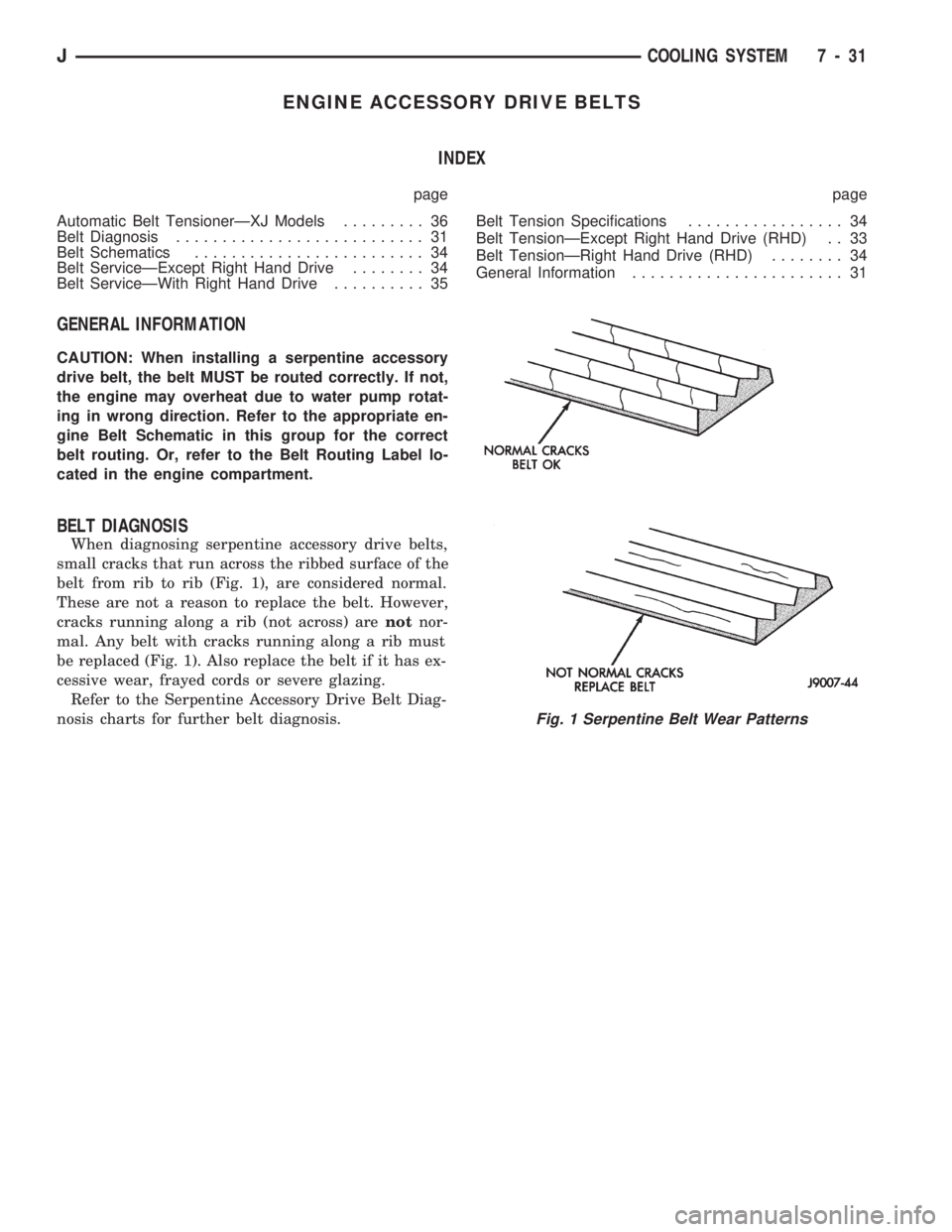
When diagnosing serpentine accessory drive belts,
small cracks that run across the ribbed surface of the
belt from rib to rib (Fig. 1), are considered normal.
These are not a reason to replace the belt. However,
cracks running along a rib (not across) arenotnor-
mal. Any belt with cracks running along a rib must
be replaced (Fig. 1). Also replace the belt if it has ex-
cessive wear, frayed cords or severe glazing.
Refer to the Serpentine Accessory Drive Belt Diag-
nosis charts for further belt diagnosis.
Fig. 1 Serpentine Belt Wear Patterns
JCOOLING SYSTEM 7 - 31
Page 266 of 1784
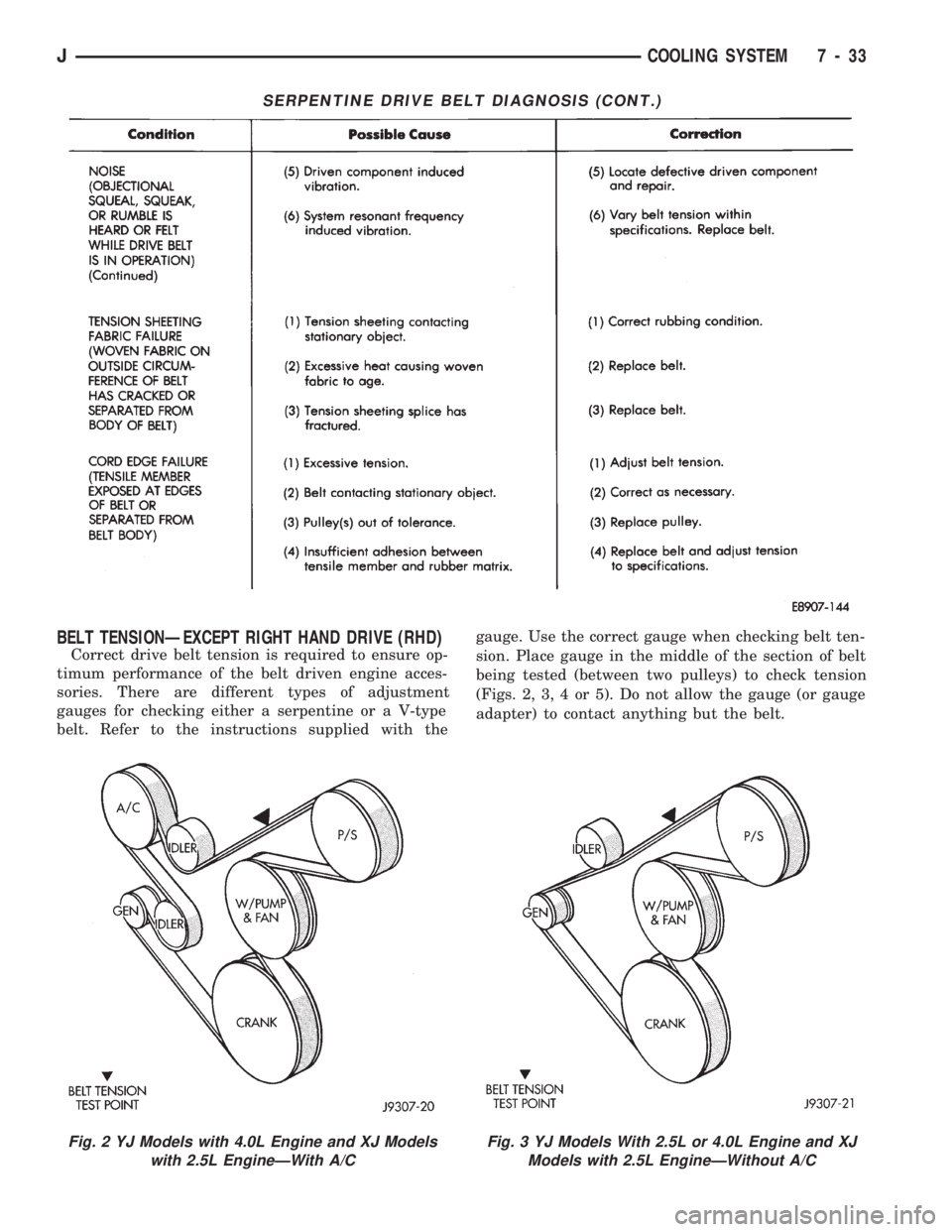
BELT TENSIONÐEXCEPT RIGHT HAND DRIVE (RHD)
Correct drive belt tension is required to ensure op-
timum performance of the belt driven engine acces-
sories. There are different types of adjustment
gauges for checking either a serpentine or a V-type
belt. Refer to the instructions supplied with thegauge. Use the correct gauge when checking belt ten-
sion. Place gauge in the middle of the section of belt
being tested (between two pulleys) to check tension
(Figs. 2, 3, 4 or 5). Do not allow the gauge (or gauge
adapter) to contact anything but the belt.
SERPENTINE DRIVE BELT DIAGNOSIS (CONT.)
Fig. 2 YJ Models with 4.0L Engine and XJ Models
with 2.5L EngineÐWith A/CFig. 3 YJ Models With 2.5L or 4.0L Engine and XJ
Models with 2.5L EngineÐWithout A/C
JCOOLING SYSTEM 7 - 33
Page 267 of 1784
BELT TENSIONÐRIGHT HAND DRIVE (RHD)
XJ MODELS WITH 4.0L ENGINE
It is not necessary to adjust belt tension on RHD
vehicles if equipped with a 4.0L engine. The engine
is equipped with an automatic belt tensioner (Fig. 7).
The tensioner maintains correct belt tension at all
times.Due to the use of this belt tensioner, DO
NOT attempt to use a belt tension gauge on this
engine.
BELT TENSION SPECIFICATIONS
Refer to the Specifications section at the end of this
group.
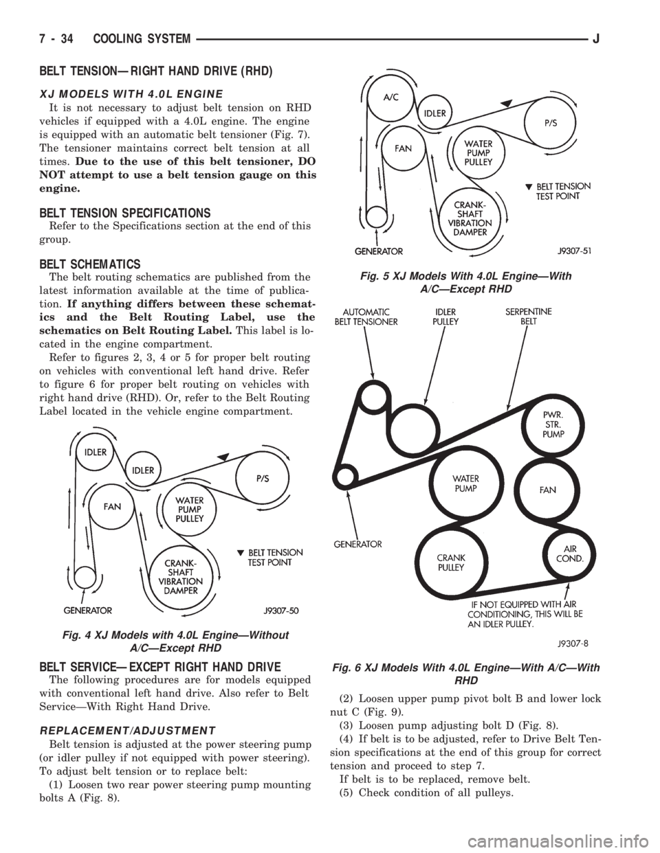
BELT SCHEMATICS
The belt routing schematics are published from the
latest information available at the time of publica-
tion.If anything differs between these schemat-
ics and the Belt Routing Label, use the
schematics on Belt Routing Label.This label is lo-
cated in the engine compartment.
Refer to figures 2, 3, 4 or 5 for proper belt routing
on vehicles with conventional left hand drive. Refer
to figure 6 for proper belt routing on vehicles with
right hand drive (RHD). Or, refer to the Belt Routing
Label located in the vehicle engine compartment.
BELT SERVICEÐEXCEPT RIGHT HAND DRIVE
The following procedures are for models equipped
with conventional left hand drive. Also refer to Belt
ServiceÐWith Right Hand Drive.
REPLACEMENT/ADJUSTMENT
Belt tension is adjusted at the power steering pump
(or idler pulley if not equipped with power steering).
To adjust belt tension or to replace belt:
(1) Loosen two rear power steering pump mounting
bolts A (Fig. 8).(2) Loosen upper pump pivot bolt B and lower lock
nut C (Fig. 9).
(3) Loosen pump adjusting bolt D (Fig. 8).
(4) If belt is to be adjusted, refer to Drive Belt Ten-
sion specifications at the end of this group for correct
tension and proceed to step 7.
If belt is to be replaced, remove belt.
(5) Check condition of all pulleys.
Fig. 4 XJ Models with 4.0L EngineÐWithout
A/CÐExcept RHD
Fig. 5 XJ Models With 4.0L EngineÐWith
A/CÐExcept RHD
Fig. 6 XJ Models With 4.0L EngineÐWith A/CÐWith
RHD
7 - 34 COOLING SYSTEMJ