1994 JEEP CHEROKEE engine
[x] Cancel search: enginePage 298 of 1784
²Metal chips are attracted by the magnets and may
not be completely removed from the starter frame.
Chips in the ring gear can lead to failure of the
starter.
2.5L STARTER MOTOR REMOVAL/INSTALLATION
XJÐ2.5L ENGINE
(1) Disconnect negative cable from battery.
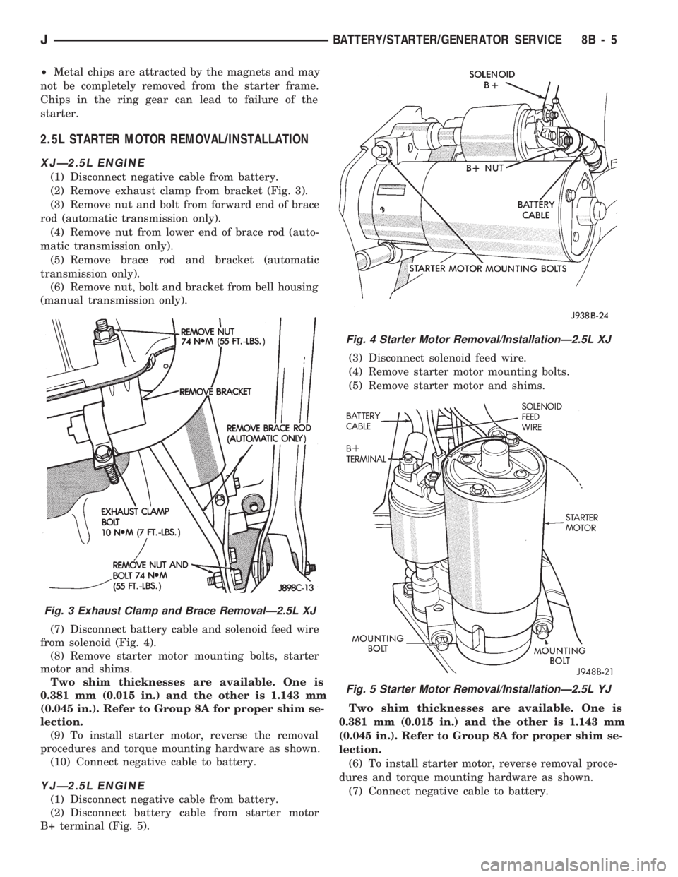
(2) Remove exhaust clamp from bracket (Fig. 3).
(3) Remove nut and bolt from forward end of brace
rod (automatic transmission only).
(4) Remove nut from lower end of brace rod (auto-
matic transmission only).
(5) Remove brace rod and bracket (automatic
transmission only).
(6) Remove nut, bolt and bracket from bell housing
(manual transmission only).
(7) Disconnect battery cable and solenoid feed wire
from solenoid (Fig. 4).
(8) Remove starter motor mounting bolts, starter
motor and shims.
Two shim thicknesses are available. One is
0.381 mm (0.015 in.) and the other is 1.143 mm
(0.045 in.). Refer to Group 8A for proper shim se-
lection.
(9) To install starter motor, reverse the removal
procedures and torque mounting hardware as shown.
(10) Connect negative cable to battery.
YJÐ2.5L ENGINE
(1) Disconnect negative cable from battery.
(2) Disconnect battery cable from starter motor
B+ terminal (Fig. 5).(3) Disconnect solenoid feed wire.
(4) Remove starter motor mounting bolts.
(5) Remove starter motor and shims.
Two shim thicknesses are available. One is
0.381 mm (0.015 in.) and the other is 1.143 mm
(0.045 in.). Refer to Group 8A for proper shim se-
lection.
(6) To install starter motor, reverse removal proce-
dures and torque mounting hardware as shown.
(7) Connect negative cable to battery.
Fig. 3 Exhaust Clamp and Brace RemovalÐ2.5L XJ
Fig. 4 Starter Motor Removal/InstallationÐ2.5L XJ
Fig. 5 Starter Motor Removal/InstallationÐ2.5L YJ
JBATTERY/STARTER/GENERATOR SERVICE 8B - 5
Page 300 of 1784
GENERATOR SERVICE PROCEDURES
GENERAL
The generator is belt-driven by the engine. All en-
gines use serpentine drive. This section will cover
generator removal and installation. The generator is
not serviceable. Information covering on-vehicle test-
ing can be found in Group 8A - Battery/Starting/
Charging Systems Diagnostics.
GENERATOR REPLACEMENTÐLEFT HAND DRIVE
WARNING: FAILURE TO DISCONNECT NEGATIVE
CABLE FROM BATTERY BEFORE DISCONNECTING
RED (OUTPUT) WIRE CONNECTOR FROM GENER-
ATOR CAN RESULT IN INJURY.
ALL YJ AND XJ WITH 2.5L ENGINE
Belt tension is adjusted at the power steering pump
(or idler pulley if not equipped with power steering).
To replace generator:
(1) Disconnect negative cable from battery.
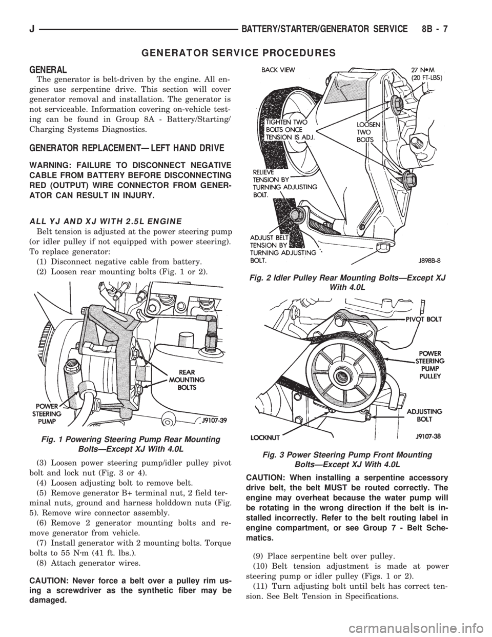
(2) Loosen rear mounting bolts (Fig. 1 or 2).
(3) Loosen power steering pump/idler pulley pivot
bolt and lock nut (Fig. 3 or 4).
(4) Loosen adjusting bolt to remove belt.
(5) Remove generator B+ terminal nut, 2 field ter-
minal nuts, ground and harness holddown nuts (Fig.
5). Remove wire connector assembly.
(6) Remove 2 generator mounting bolts and re-
move generator from vehicle.
(7) Install generator with 2 mounting bolts. Torque
bolts to 55 Nzm (41 ft. lbs.).
(8) Attach generator wires.
CAUTION: Never force a belt over a pulley rim us-
ing a screwdriver as the synthetic fiber may be
damaged.CAUTION: When installing a serpentine accessory
drive belt, the belt MUST be routed correctly. The
engine may overheat because the water pump will
be rotating in the wrong direction if the belt is in-
stalled incorrectly. Refer to the belt routing label in
engine compartment, or see Group 7 - Belt Sche-
matics.
(9) Place serpentine belt over pulley.
(10) Belt tension adjustment is made at power
steering pump or idler pulley (Figs. 1 or 2).
(11) Turn adjusting bolt until belt has correct ten-
sion. See Belt Tension in Specifications.
Fig. 1 Powering Steering Pump Rear Mounting
BoltsÐExcept XJ With 4.0L
Fig. 2 Idler Pulley Rear Mounting BoltsÐExcept XJ
With 4.0L
Fig. 3 Power Steering Pump Front Mounting
BoltsÐExcept XJ With 4.0L
JBATTERY/STARTER/GENERATOR SERVICE 8B - 7
Page 301 of 1784
(12) Tighten rear mounting bolts, pivot bolt, and
lock nut to 27 Nzm (20 ft. lbs.) torque.
(13) Connect negative cable to battery.
XJ WITH 4.0L ENGINE
Belt tension is adjusted at the power steering
pump.
To replace generator:
(1) Disconnect negative cable from battery.
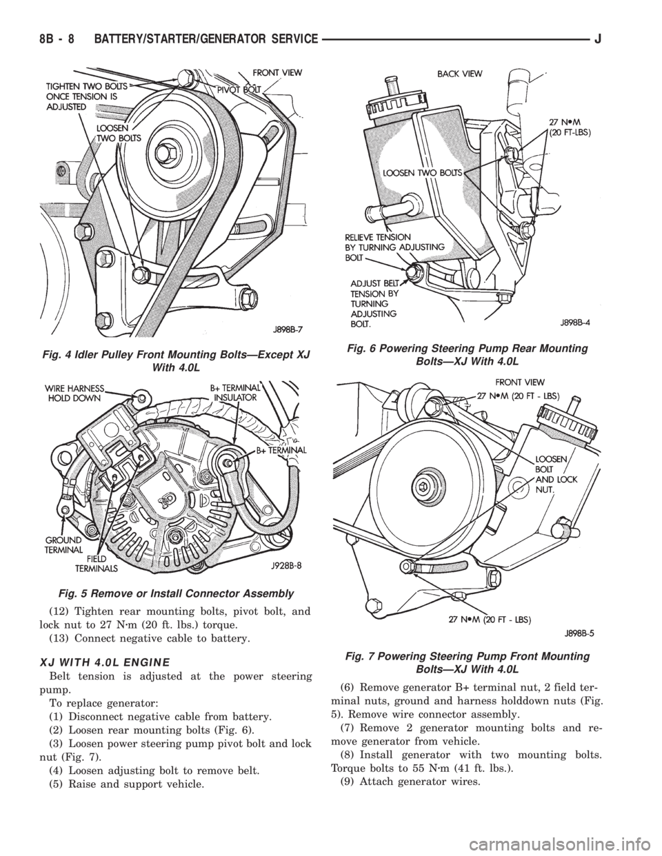
(2) Loosen rear mounting bolts (Fig. 6).
(3) Loosen power steering pump pivot bolt and lock
nut (Fig. 7).
(4) Loosen adjusting bolt to remove belt.
(5) Raise and support vehicle.(6) Remove generator B+ terminal nut, 2 field ter-
minal nuts, ground and harness holddown nuts (Fig.
5). Remove wire connector assembly.
(7) Remove 2 generator mounting bolts and re-
move generator from vehicle.
(8) Install generator with two mounting bolts.
Torque bolts to 55 Nzm (41 ft. lbs.).
(9) Attach generator wires.
Fig. 4 Idler Pulley Front Mounting BoltsÐExcept XJ
With 4.0L
Fig. 5 Remove or Install Connector Assembly
Fig. 6 Powering Steering Pump Rear Mounting
BoltsÐXJ With 4.0L
Fig. 7 Powering Steering Pump Front Mounting
BoltsÐXJ With 4.0L
8B - 8 BATTERY/STARTER/GENERATOR SERVICEJ
Page 302 of 1784
CAUTION: Never force a belt over a pulley rim us-
ing a screwdriver as the synthetic fiber may be
damaged.
CAUTION: When installing a serpentine accessory
drive belt, the belt MUST be routed correctly. The
engine may overheat because the water pump will
be rotating in the wrong direction if the belt is in-
stalled incorrectly. Refer to the belt routing label in
engine compartment, or see Group 7 - Belt Sche-
matics.
(10) Place serpentine belt over pulley.
(11) Belt tension adjustment is made at power
steering pump (Fig. 6).
(12) Turn adjusting bolt until belt has correct ten-
sion. See Belt Tension in Specifications.
(13) Tighten rear mounting bolts, pivot bolt, and
lock nut to 27 Nzm (20 ft. lbs.) torque.
(14) Remove support and lower vehicle.
(15) Connect negative cable to battery.
GENERATOR REPLACEMENTÐRIGHT HAND DRIVE
The generator used on the right hand drive is the
same as used on left hand drive. However, the
mounting and accessory drive belt installation are
different.
WARNING: FAILURE TO DISCONNECT NEGATIVE
CABLE FROM BATTERY BEFORE DISCONNECTING
RED (OUTPUT) WIRE CONNECTOR FROM GENER-
ATOR CAN RESULT IN INJURY.
(1) Remove negative cable from battery.
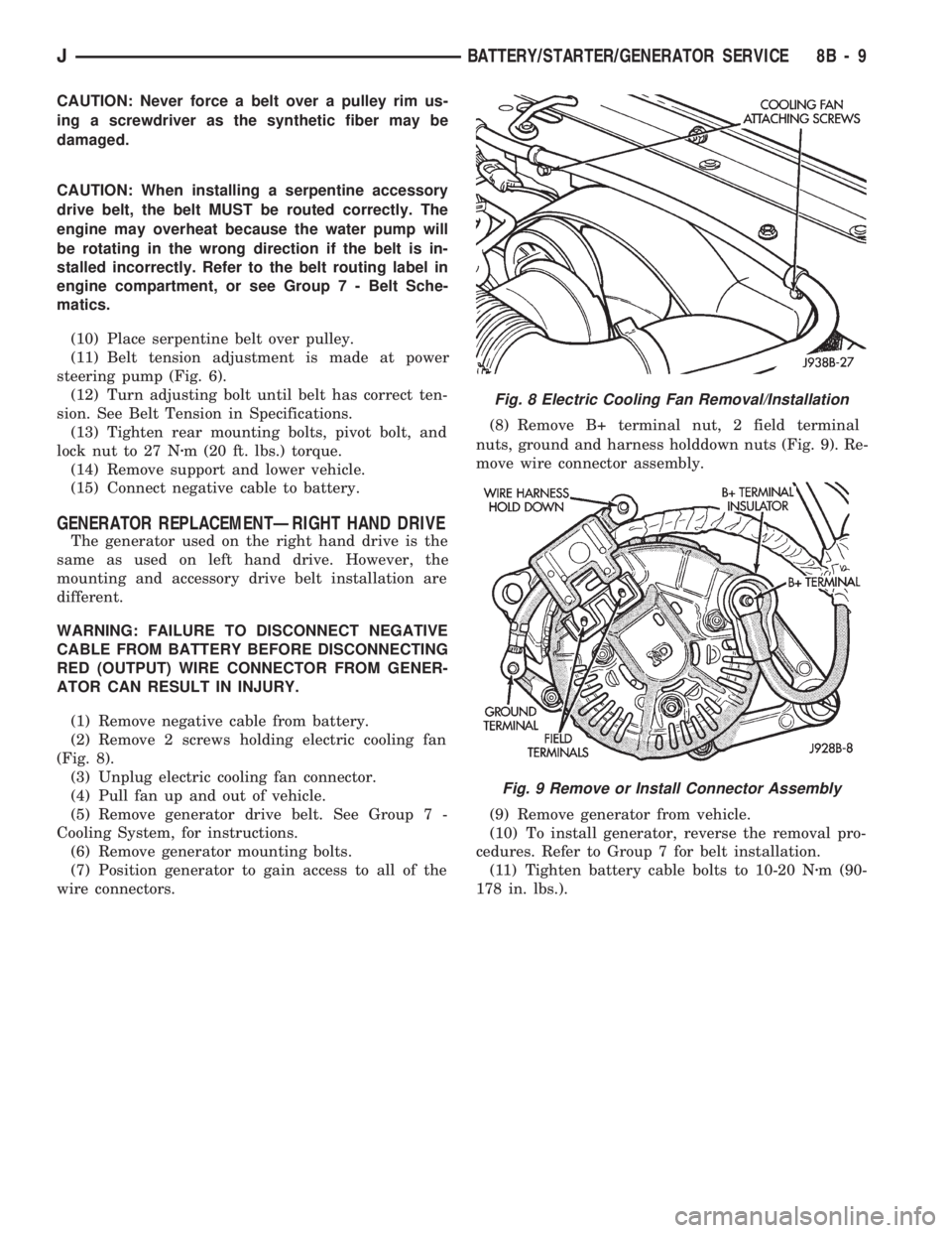
(2) Remove 2 screws holding electric cooling fan
(Fig. 8).
(3) Unplug electric cooling fan connector.
(4) Pull fan up and out of vehicle.
(5) Remove generator drive belt. See Group 7 -
Cooling System, for instructions.
(6) Remove generator mounting bolts.
(7) Position generator to gain access to all of the
wire connectors.(8) Remove B+ terminal nut, 2 field terminal
nuts, ground and harness holddown nuts (Fig. 9). Re-
move wire connector assembly.
(9) Remove generator from vehicle.
(10) To install generator, reverse the removal pro-
cedures. Refer to Group 7 for belt installation.
(11) Tighten battery cable bolts to 10-20 Nzm (90-
178 in. lbs.).
Fig. 8 Electric Cooling Fan Removal/Installation
Fig. 9 Remove or Install Connector Assembly
JBATTERY/STARTER/GENERATOR SERVICE 8B - 9
Page 304 of 1784
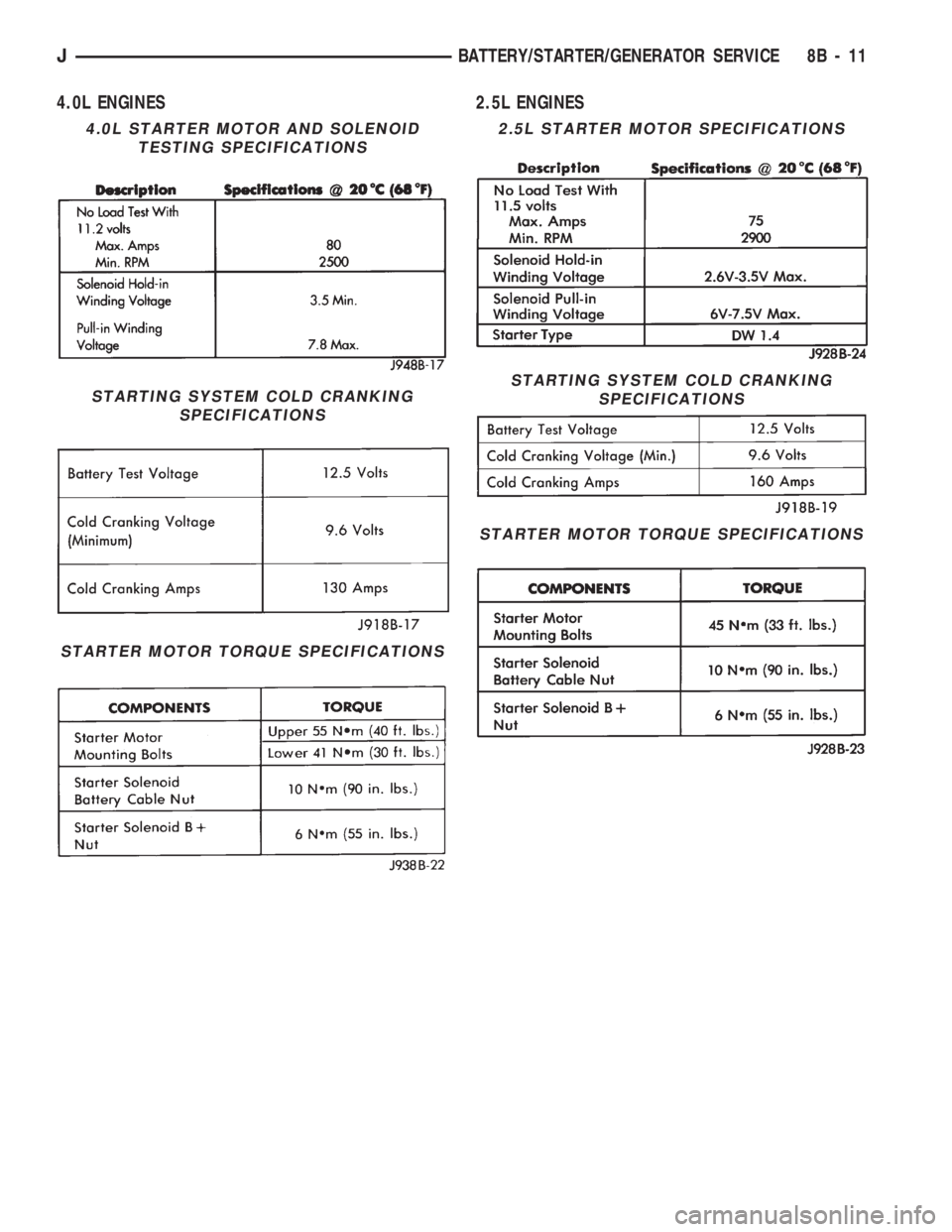
4.0L ENGINES 2.5L ENGINES
4.0L STARTER MOTOR AND SOLENOID
TESTING SPECIFICATIONS
STARTING SYSTEM COLD CRANKING
SPECIFICATIONS
STARTER MOTOR TORQUE SPECIFICATIONS
2.5L STARTER MOTOR SPECIFICATIONS
STARTING SYSTEM COLD CRANKING
SPECIFICATIONS
STARTER MOTOR TORQUE SPECIFICATIONS
JBATTERY/STARTER/GENERATOR SERVICE 8B - 11
Page 309 of 1784
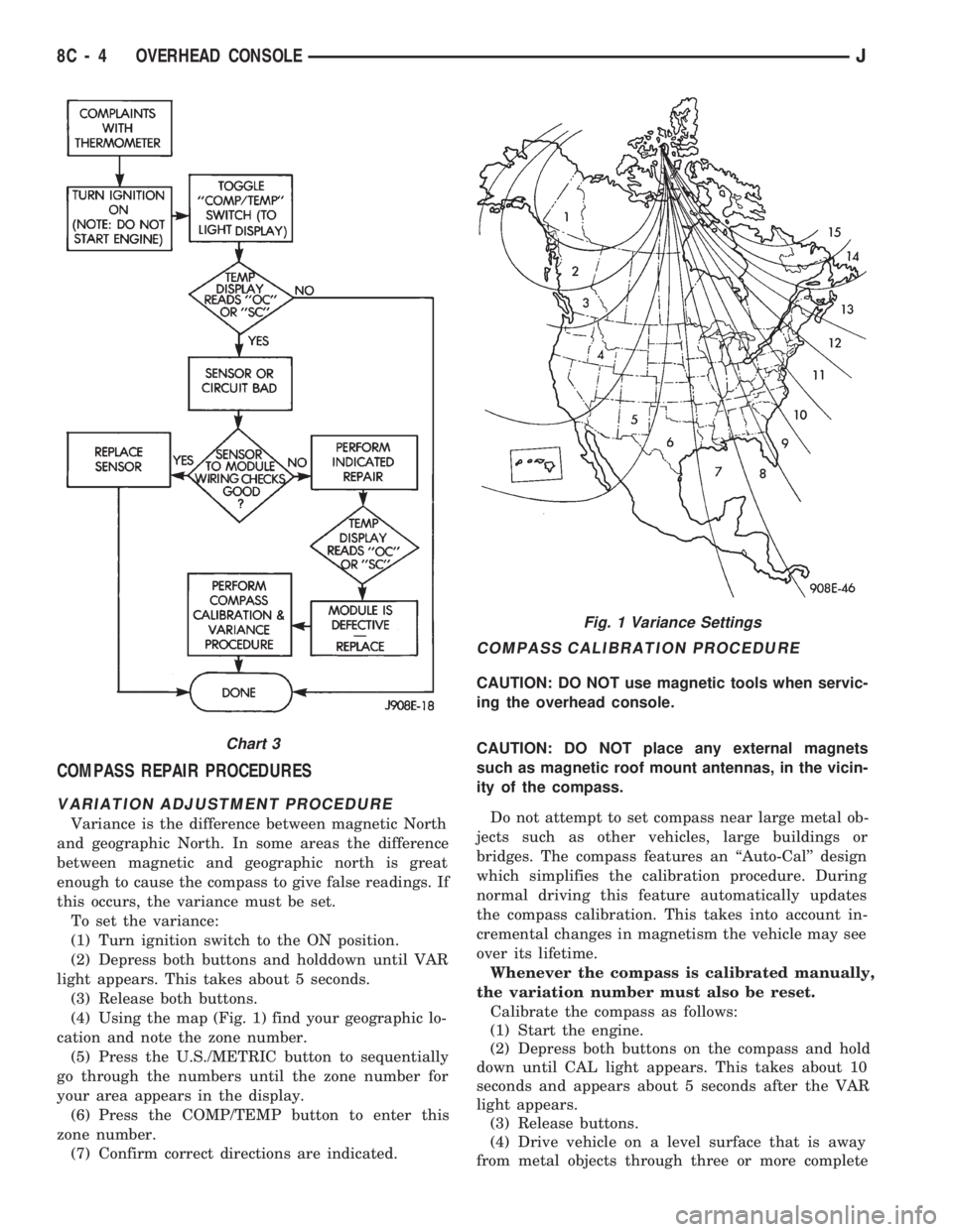
COMPASS REPAIR PROCEDURES
VARIATION ADJUSTMENT PROCEDURE
Variance is the difference between magnetic North
and geographic North. In some areas the difference
between magnetic and geographic north is great
enough to cause the compass to give false readings. If
this occurs, the variance must be set.
To set the variance:
(1) Turn ignition switch to the ON position.
(2) Depress both buttons and holddown until VAR
light appears. This takes about 5 seconds.
(3) Release both buttons.
(4) Using the map (Fig. 1) find your geographic lo-
cation and note the zone number.
(5) Press the U.S./METRIC button to sequentially
go through the numbers until the zone number for
your area appears in the display.
(6) Press the COMP/TEMP button to enter this
zone number.
(7) Confirm correct directions are indicated.
COMPASS CALIBRATION PROCEDURE
CAUTION: DO NOT use magnetic tools when servic-
ing the overhead console.
CAUTION: DO NOT place any external magnets
such as magnetic roof mount antennas, in the vicin-
ity of the compass.
Do not attempt to set compass near large metal ob-
jects such as other vehicles, large buildings or
bridges. The compass features an ``Auto-Cal'' design
which simplifies the calibration procedure. During
normal driving this feature automatically updates
the compass calibration. This takes into account in-
cremental changes in magnetism the vehicle may see
over its lifetime.
Whenever the compass is calibrated manually,
the variation number must also be reset.
Calibrate the compass as follows:
(1) Start the engine.
(2) Depress both buttons on the compass and hold
down until CAL light appears. This takes about 10
seconds and appears about 5 seconds after the VAR
light appears.
(3) Release buttons.
(4) Drive vehicle on a level surface that is away
from metal objects through three or more complete
Fig. 1 Variance Settings
Chart 3
8C - 4 OVERHEAD CONSOLEJ
Page 314 of 1784

IGNITION SYSTEMS
CONTENTS
page page
COMPONENT IDENTIFICATION/SYSTEM
OPERATION.......................... 1
COMPONENT REMOVAL/INSTALLATION..... 20DIAGNOSTICS/SERVICE PROCEDURES....... 8
IGNITION SWITCH...................... 30
SPECIFICATIONS....................... 33
COMPONENT IDENTIFICATION/SYSTEM OPERATION
INDEX
page page
Automatic Shut Down (ASD) Relay............ 1
Camshaft Position Sensor................... 1
Crankshaft Position Sensor.................. 2
Distributors.............................. 3
Engine Coolant Temperature Sensor........... 4
General Information........................ 1Ignition Coil.............................. 4
Intake Manifold Air Temperature Sensor........ 5
Manifold Absolute Pressure (MAP) Sensor...... 5
Powertrain Control Module (PCM)............. 6
Throttle Position Sensor.................... 6
GENERAL INFORMATION
Throughout this group, references are made to par-
ticular vehicle models by alphabetical designation
(XJ or YJ) or by the particular vehicle nameplate. A
chart showing a breakdown of alphabetical designa-
tions is included in the Introduction group at the be-
ginning of this manual.
This section of the group, Component Identifica-
tion/System Operation, will discuss ignition system
operation and will identify ignition system compo-
nents.
For diagnostic procedures and adjustments, refer to
the Diagnostics/Service Procedures section of this
group.
For removal and installation of ignition system
components, refer to the Component Removal/Instal-
lation section of this group.
For other useful information, refer to On-Board Di-
agnostics in the General Diagnosis sections of Group
14, Fuel System in this manual.
For operation of the DRB Scan Tool, refer to the
appropriate Powertrain Diagnostic Procedures ser-
vice manual.
An Ignition specifications section is included at the
end of this group. A general Maintenance Schedule
(mileage intervals) for ignition related items can be
found in Group 0, Lubrication and Maintenance. This
schedule can also be found in the Owners Manual.
IGNITION SYSTEMS
A multi-port, fuel injected engine is used on all
models. The ignition system is controlled by the Pow-
ertrain Control Module (PCM) on all engines. The
PCM was formerly referred to as the SBEC or engine
controller.
The ignition system consists of:
²Spark Plugs
²Ignition Coil
²Secondary Ignition Cables
²Ignition distributor (contains rotor and camshaft
position sensor)
²Powertrain Control Module (PCM)
²Crankshaft Position Sensor
AUTOMATIC SHUT DOWN (ASD) RELAY
The automatic shut down (ASD) relay is located in
the Power Distribution Center (PDC) near the bat-
tery (Fig. 1 or 2). As one of its functions, it will sup-
ply battery voltage to the ignition coil. The ground
circuit for the ASD relay is controlled by the Power-
train Control Module (PCM). The PCM regulates
ASD relay operation by switching the ground circuit
on-and-off.
CAMSHAFT POSITION SENSOR
The camshaft position sensor is located in the igni-
tion distributor (Figs. 3 or 4) on all engines.
The camshaft position sensor contains a hall effect
device called a sync signal generator to generate a
fuel sync signal. This sync signal generator detects a
JIGNITION SYSTEMS 8D - 1
Page 315 of 1784
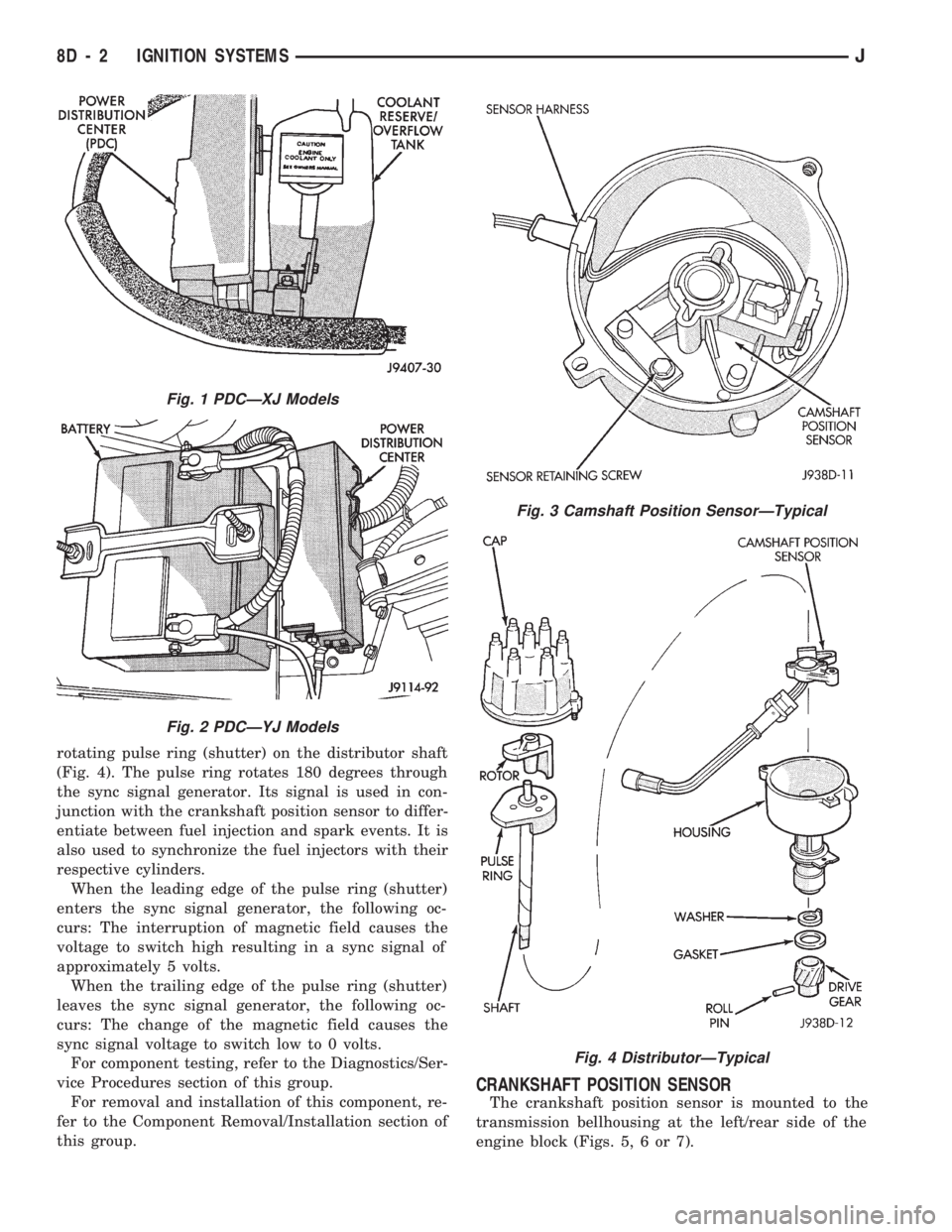
rotating pulse ring (shutter) on the distributor shaft
(Fig. 4). The pulse ring rotates 180 degrees through
the sync signal generator. Its signal is used in con-
junction with the crankshaft position sensor to differ-
entiate between fuel injection and spark events. It is
also used to synchronize the fuel injectors with their
respective cylinders.
When the leading edge of the pulse ring (shutter)
enters the sync signal generator, the following oc-
curs: The interruption of magnetic field causes the
voltage to switch high resulting in a sync signal of
approximately 5 volts.
When the trailing edge of the pulse ring (shutter)
leaves the sync signal generator, the following oc-
curs: The change of the magnetic field causes the
sync signal voltage to switch low to 0 volts.
For component testing, refer to the Diagnostics/Ser-
vice Procedures section of this group.
For removal and installation of this component, re-
fer to the Component Removal/Installation section of
this group.
CRANKSHAFT POSITION SENSOR
The crankshaft position sensor is mounted to the
transmission bellhousing at the left/rear side of the
engine block (Figs. 5, 6 or 7).
Fig. 1 PDCÐXJ Models
Fig. 2 PDCÐYJ Models
Fig. 3 Camshaft Position SensorÐTypical
Fig. 4 DistributorÐTypical
8D - 2 IGNITION SYSTEMSJ