Page 33 of 57

BODY
CONTENTS
,I
i
1AEROPARTS . . . . . . . . . . . . . . . . . . . . . . . . . . . . . . . . . . . . . . . . . .72
; CENTRAL DOOR LOCKING SYSTEM . . . . . . . . . . .68
’DOORASSEMBLY . . . . . . . . . . . . . . . . . . . . . . . . . . . . . . . . . . . .61
DOOR GLASS AND REGULATOR................
64
DOOR HANDLE AND LATCH.....................67QUARTER WINDOWGLASS..
...............
..i..59
REAR BUMPER........................................41
REARSEAT.........................................;..93
SEATBELT.............................................
94
SERVICE ADJUSTMENT PROCEDURES........30
Door Adjustment....................................31
Door Glass Adjustment............................31
Door Inside Handle Play Check...................31
Door Outside Handle Play Check................31
Floor PanInspection..............................
32
Fuel Filler Door Adjustment.......................30
Hood Adjustment...................................30
Liftgate Adjustment.................................30
Water Test...........................................
32
SPECIAL TOOLS....................*..........c......
5
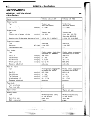
SPECIFICATIONS.....................................2
General Specifications...........................;..2
Lubricants.............................................5
Sealants and Adhesives...........................5
Service Specifications..............................3
Torque Specifications..............................3
SUNROOF...............................................
77
TRIMS....................................................
85
TROUBLESHOOTING................................6
WINDOWGLASS.....................................52
WINDSHIELD...........................................56
DOORMIRROR........................................
70
DOOR
MOULDING AND
DRIP LINE WEATHERSTRIP........................
70
DOORRUNCHANNEL...............................
69
DOOR TRIM AND WATERPROOF FILM........
63
ELECTRIC REMOTE CONTROLLED
MIRRORSWITCH.....................................
71
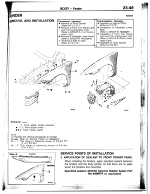
FENDER..................................................
49
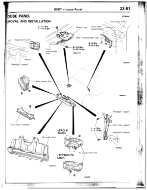
FLOORCONSOLE....................................
84
FRONTBUMPER......................................37
FRONTSEAT...........................................90
FUEL TANK FILLER DOOR.........................
36
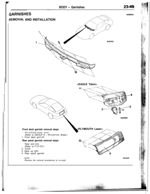
GARNISHES............................................45
HEADLINING...........................................89
HOOD....................................................
33
INSTRUMENTPANEL.,..............................
79
Lll=l’GATE...............................................
35
LIFTGATE WINDOW GLASS......................60
LOOSEPANEL . . . . . . . . . . . . . . . . . . . . . . . . . . . . . . . . . . . . . . . . .51
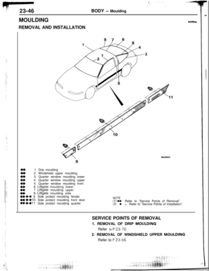
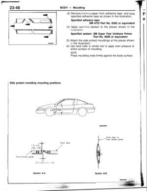
MOULDING.............................................
46
POWERWINDOW....................................65
N23AA--
Page 34 of 57
BODY - Hood23-33
IOODN23HAA.S
k
EMOVAL AND INSTALLATION9,17-26 Nm
12-19
ftlbs.11/9-14 Nm7- 10 ft.lbs./
!, 9-14Nm/
9-J/
l 4
l 4
l 4
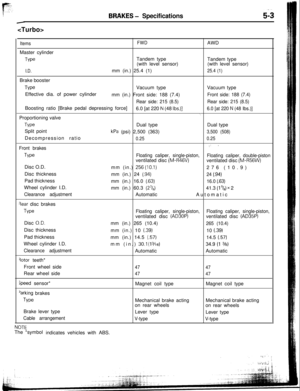
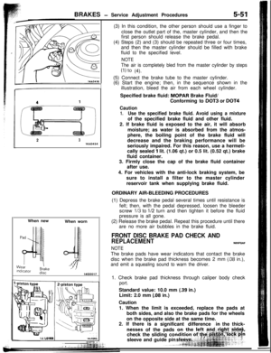
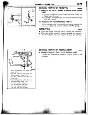
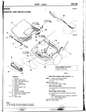
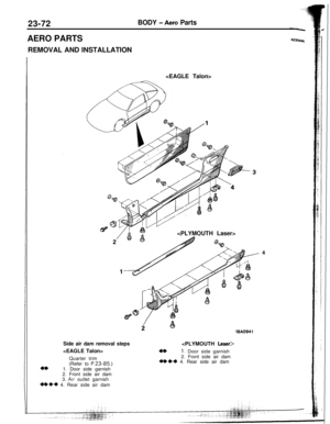
Removal
1.Bumper2.Hood weatherstrip3. Hood front weatherstrip
4.Heat protector5.Hood weatherstrip
6.Bumper7. Hood support rod
8.Bumper9.Bumper0.Bumper bracket
1. Hood lock release handle
2.Front fascia bracket3.Clip4.Hood latch
NOTE(1) Reverse the removal procedures to reinstsll.(2) l : Refer to “Service Pyrnts of Installatron”.
19A0950
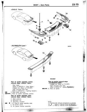
Hood lock release cable removal steps
+a 11. Hood lock release handle
12. Front fascia bracket13.
CllP
~~ 14. Hood latch15. Hood lock release cable
Hood removal steps16. Connection for washer tube and nozzle
17. Hood
Hood hinge removal steps16. Connection for washer tube and nozzle
i-I. Hood
Windshield wiper arms (Refer to GROUP
5 1 - Windshield Wiper.)
18. Front deck garnish
+d 19. Hood hinge
Page 35 of 57
-
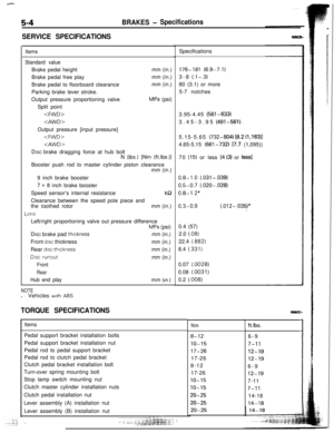
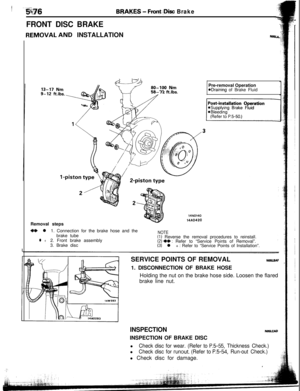
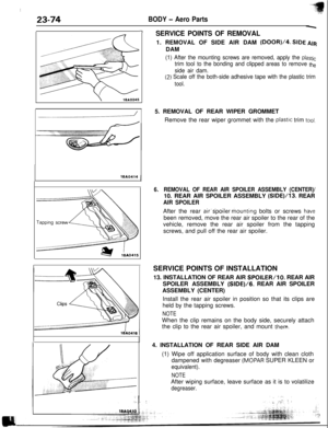
23-34BODY - HoodSERVICE POINTS
OF INSTALLATION
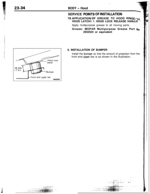
19.APPLICATION Or GREASE TO HOOD HINGE/l4HOOD LATCH/l 1. HOOD LOCK RELEASE HANDLE
’Apply multipurpose grease to all moving parts.
Grease: MOPAR Multipurpose Grease Part
No2932524 or equivalent
18AO3926. INSTALLATION OF BUMPER
Install the bumper so that the amount of projection from thefront end
@per bar is as shown in the illustration.
Page 36 of 57

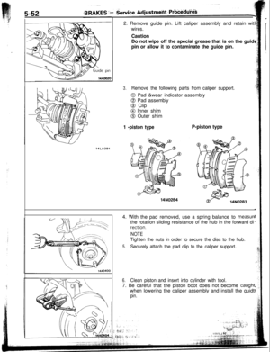
3. Liftgate outer weatherstrip
4. Liftgate damper (lower)
5.")
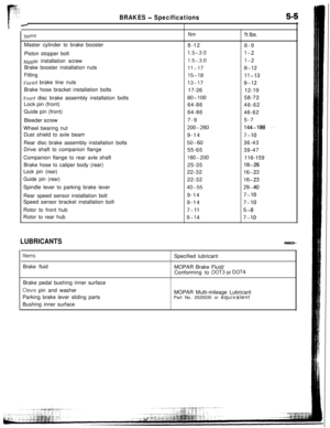
BODY - Liftgate23-35
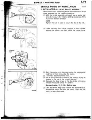
FTGATEN230AAT
EMOVAL AND INSTALLATION
11-16 Nm
8- 12 ft.lbs.\9-14 Nm
7- 10 ftlbs.
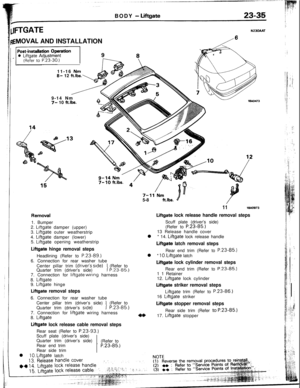
1. Bumper
2. Llftgate damper (upper)
3. Liftgate outer weatherstrip
4. Liftgate damper (lower)
5. Liftgate opening weatherstrip
Liftgate hinge removal stepsHeadlining (Refer to
P.23-89.)6. Connection for rear washer tube
Center pillar trim (drtver’s side)
Quarter trim (driver’s side)
1(Refer toP.23-85.)7. Connection for liftgate wiring harness
8. Liftgate
9. Liftgate hinge
Liftgate removal steps6. Connection for rear washer tube
Center pillar trim (driver’s side)(Refer to
Quarter trim (driver’s side)
1P.23-85.)7. Connection for
liftgate wiring harness
8. Liftgate
Liftgate lock release cable removal stepsRear seat (Refer to
P.23-93.)Scuff plate (driver’s side)
Quarter trim (driver’s side)
(Refer to
Rear end trim
’ P.23-85.)Rear side trim
l
10. Liftgate latch5-8 ftlbs.
4/
1118AO973
Liftgate lock release handle removal stepsScuff plate (driver’s side)
(Refer to
P.23-85.)13 Release handle cover
l * 14.
Liftgate lock release handle
Liftgate latch removal stepsRear end trim (Refer to
P.23-85.)l *
10. Liftgate latch
Liftgate lock cylinder removal stepsRear end trim (Refer to P-23-85.)
1 1 Retainer
4*12.
Liftgate lock cylinder
Liftgate striker removal steps
Liftgate trim (Refer to P.23-86.)16
Liftgate striker
Liftgate stopper removal stepsRear side trim (Refer
td P.23-85.)
17. Liftgate stopper
Page 37 of 57

._-_,. -/a,_ . . ._ :-.
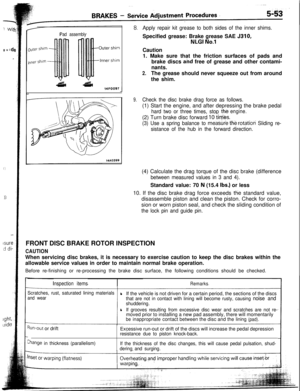
nkFiller Door
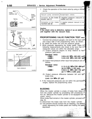
FUEL TANK FILLER DOOR
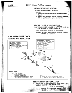
REMOVAL AND INSTALLATIONSERVICE POINTS OF REMOVAL17. REMOVAL OF
LIFTGATE STOPPER
Caution1. Never try to disassemble the
liigate gas spring crbum it.
2. Always bore a hole in the gas spring to
release the
interior gas before the spring is discarded.
SERVICE POINTS OF INSTALLATION14,APPLICATION OF GREASE TO
LIFTGATE LOCK RF-LEASE HANDLE/
10. LIFTGATE LATCH
Apply multipurpose grease to all moving parts
Grease: MOPAR Multipurpose Grease Part NO.
2932524 or equivalent
N23JAAa
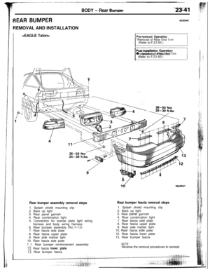
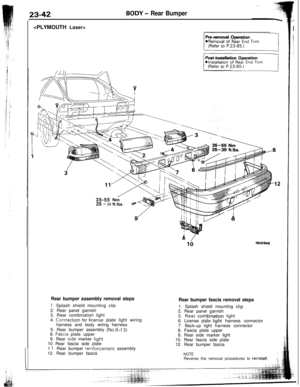
Pre-removal Operation0 Removal of Rear Seat
Post-installation Operationl Installation of Rear Side Trim
Quarter Trim and Scuff Plate
(Refer to P.2385.)
0 Installation of Rear Seat
(Refer to P.23-93.)0 Fuel Filler Door Adjustment
(Refer to P.23-30.)Removal steps+a
1. Fuel filler door2. Fuel filler door hookWA0462
3. Release hatidle coverNOTEl * 4. Fuel filler door lock release handle(1) Reverse the removal procedures to reinstall.5. Fuel filler door lock release cable(2) +a : Refer to “Service Points of Installation”.
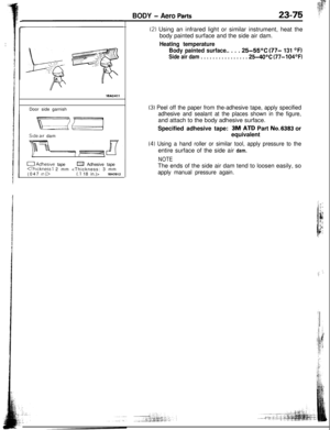
SERVICE POINTS OF INSTALLATION4.
APPLICATION OF GREASE TO FUEL FILLER,DOOR LOCK j
:(“‘: ,: : ,.-;gz/ :,; Apply multipurpose gre
:’ j:: -:l : :. ,;&r: &;iGrease: MOPARMu
; _
Page 38 of 57
-- .__.,_...__
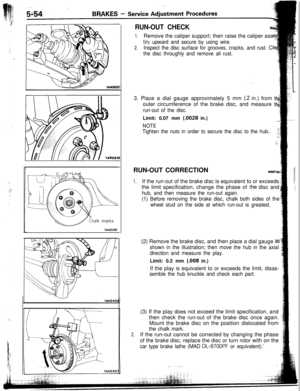
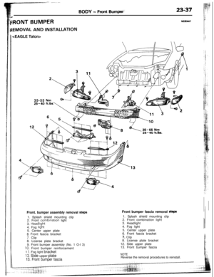
BODY - Front Bumped’23i37
RONT BUMPERNk4AY
EMOVAL AND INSTALLATION
35-55
25-40
\35-55Nma.-11 ._ II
Front bumper fascia removal Steps1. Splash shield mounting clip
2. Front combination light
3. Headlight
4. Fog light
5. Center upper plate
6. Front fascia bracket
7. Clip
8. License plate bracket
12. Side upper plate
13. Front bumper fasciaFront. bumper assembly removal steps1. Splash shield mounting clip
2. Front
combrnation light
3. Headlrght
4. Fog
light5. Center upper plate
6 Front fascia bracket
7. Clip
8. License plate bracket
9. Front bumper assembly (No. 1 O-l 3)
10. Front bumper reinforcement
1
1, Fog light bracket
12. Side upper plate
13. Front bumper fascia
NOTEReverse the removal procedures to reinstall.
Page 39 of 57
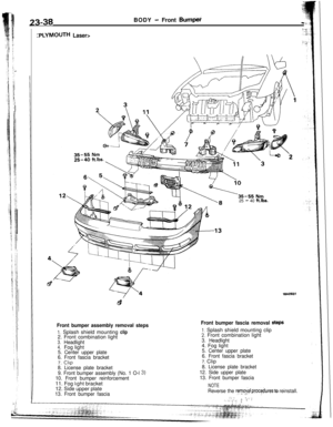
:PLYMOUTH Laser>25
- 40 ft.lbs.
23-38BODY - Front Bum$i
Front bumper assembly removal steps
1. Splash shield mounting clip
2. Front combination light
3.Headlight4.Fog light5. Center upper plate
6. Front fascia bracket7.
CllP8. License plate bracket
9. Front bumper assembly (No. 1 O-l
3)10. Front bumper reinforcement11. Fog light bracket
12. Side upper plate
13. Front bumper fascia
Front bumper fascia removal StePS
1, Splash shield mounting clip2. Front combination light
3. Headlight4. Fog light
5. Center upper plate
6. Front fascia bracket7. Clip
8. License plate bracket
12. Side upper plate
13. Front bumper fascia
NOTE
Reverse the ryv,o&+ ,rjrocebures to reinstall.,.,ir ,’.!,I,(1 ,(, /.; 1, !
Page 40 of 57
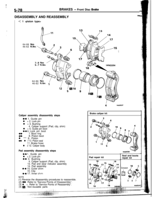
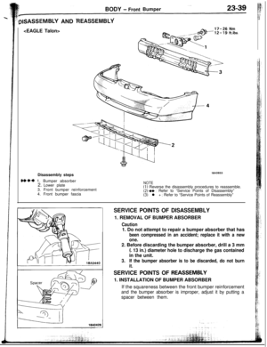
BODY - FrontBumper
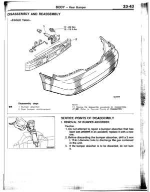
‘plSASSEMBLY ANDREASSEMBLY
Nmftlbs.
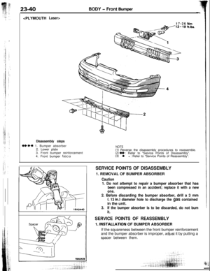
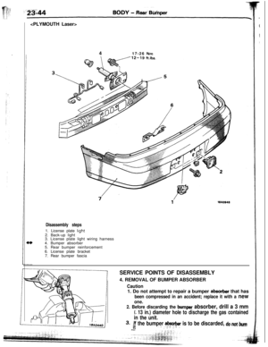
Disassembly steps
@*I)* 1. Bumper absorber
2. Lower plate
3. Front bumper reinforcement
4. Front bumper fascia
19AQ933
NOTE(1) Reverse the disassembly procedures to reassemble.(2) ++ : Refer to “Service Points of Disassembly”(3) l + : Refer to “Service Points of Reassembly”
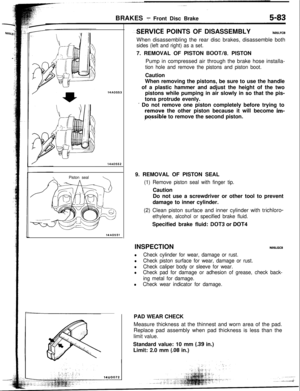
SERVICE POINTS OF DISASSEMBLY1. REMOVAL OF BUMPER ABSORBER
Caution1. Do not attempt to repair a bumper absorber that has
been compressed in an accident; replace it with a new
one.2. Before discarding the bumper absorber, drill a 3 mm
(. 13 in.) diameter hole to discharge the gas containedin the unit.
3.If the bumper absorber is to be discarded, do not burn
it.
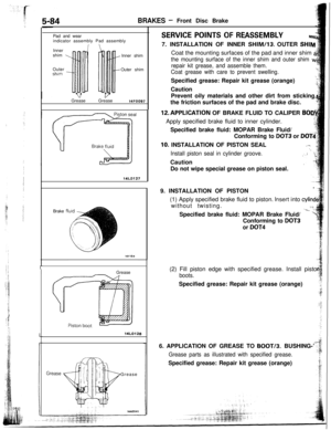
SERVICE POINTS OF REASSEM.BLY1. INSTALLATION OF BUMPER ABSORBER
If the squareness between the front bumper reinforcement
and the bumper absorber is improper, adjust it by putting a
spacer between them.


* 1. Bumper absorber
2. Lower plate
3. Front bumper reinforcement
4. Front bumper fascia
19AQ933
NOTE(1) Rev")