Page 25 of 57
 as a set.7. R")
BRAKES 7 Front Disc Brake5-83
14AO55314A0552
\Piston seal\
14AO551
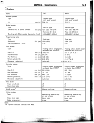
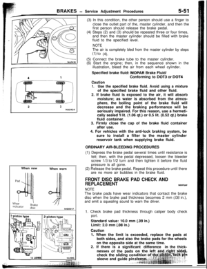
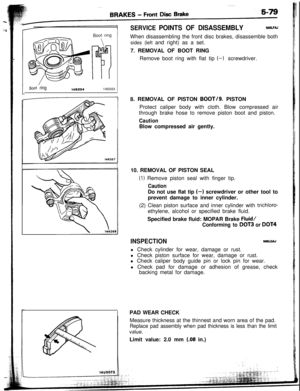
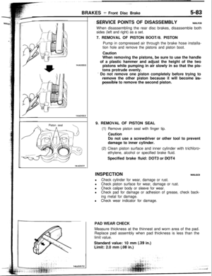
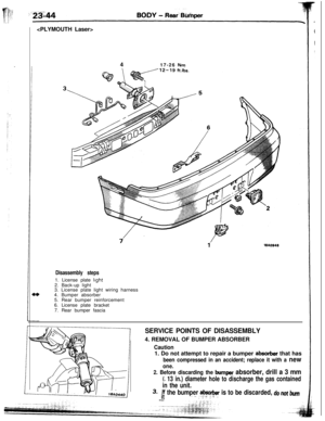
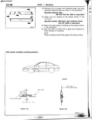
--SERVICE POINTS OF DISASSEMBLYiUO5LFCBWhen disassembling the rear disc brakes, disassemble both
sides (left and right) as a set.7. REMOVAL OF PISTON
BOOT/8. PISTON
Pump in compressed air through the brake hose installa-
tion hole and remove the pistons and piston boot.Caution
When removing the pistons, be sure to use the handle
of a plastic hammer and adjust the height of the two
pistons while pumping in air slowly in so that the pis-
tons protrude evenly.
I Do not remove one piston completely before trying to
,remove the other piston because it will become im-Possible to remove the second piston.
9. REMOVAL OF PISTON SEAL
(1) Remove piston seal with finger tip.Caution
Do not use a screwdriver or other tool to prevent
damage to inner cylinder.
(2) Clean piston surface and inner cylinder with trichloro-
ethylene, alcohol or specified brake fluid.Specified brake fluid:
DOT3 or DOT4INSPECTION
NOSLGCB
lCheck cylinder for wear, damage or rust.
lCheck piston surface for wear, damage or rust.
lCheck caliper body or sleeve for wear.
lCheck pad for damage or adhesion of grease, check back-
ing metal for damage.
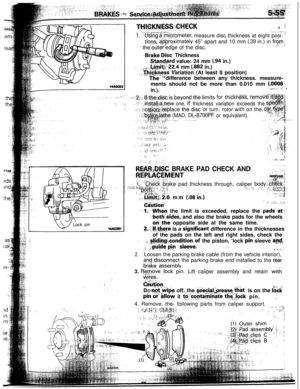
lCheck wear indicator for damage.PAD WEAR CHECK
Measure thickness at the thinnest and worn area of the pad.
Replace pad assembly when pad thickness is less than the
limit value.Standard value: 10 mm
(.39 in.)
Limit: 2.0 mm
(.08 in.)
Page 26 of 57

BRAKES -Front Disc Brake
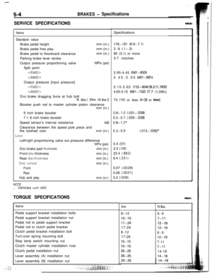
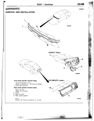
l-Pad and wear
indicator assembly Pad assembly
Inner
shim
Outershim
11Inner shim
Outer shim
GreaseGrease14FOO97
al
14LO127Brake fl
Grease
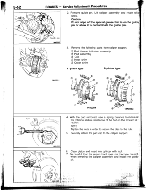
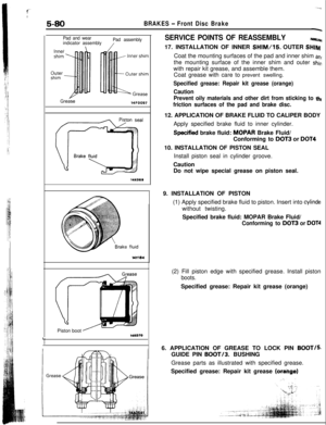
14LO128GreaseSERVICE
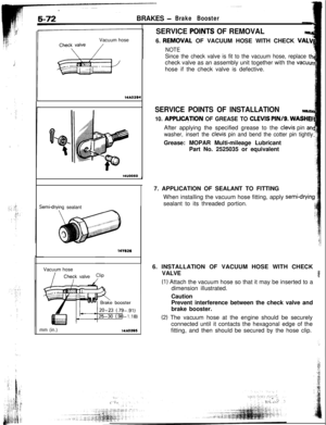
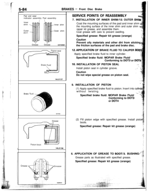
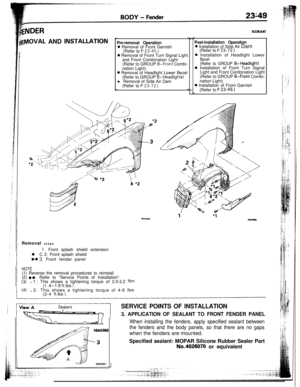
POINTS OF REASSEMBLYNW7. INSTALLATION OF INNER
SHIM/13. OUTER SHIM
Coat the mounting surfaces of the pad and inner shim
a
the mounting surface of the inner shim and outer shim vv
repair kit grease, and assemble them.
Coat grease with care to prevent swelling.Specified grease: Repair kit grease (orange)
Caution
Prevent oily materials and other dirt from sticking,
the friction surfaces of the pad and brake disc.12.APPLlCATlON OF BRAKE FLUID TO CALIPER
BODjApply specified brake fluid to inner cylinder.,.;Specified brake fluid: MOPAR Brake Fluid/;:ti
”Conforming to
DOT3 or DOT4
10. INSTALLATION OF PISTON SEAL..I.‘”Install piston seal in cylinder groove.Caution
Do not wipe special grease on piston seal.
9. INSTALLATION OF PISTON.
(1) Apply specified brake fluid to piston.
Insert into cylindlwithout twisting.
(/ifiL-_. i//Specified brake fluid: MOPAR Brake Fluid/
Conforming to
DOT3
or
DOT4(2) Fill piston edge with specified grease. Install pistc
boots.Specified grease: Repair kit grease (orange)
6. APPLICATION OF GREASE TO BOOT/3. BUSHING-’
Grease parts as illustrated with specified grease.Specified grease: Repair kit grease (orange)
Page 27 of 57
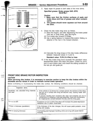
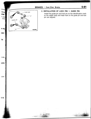
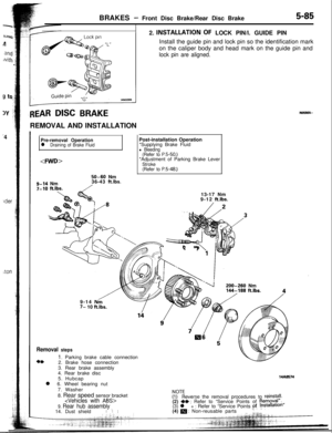
BRAKES - Front Disc Brake/Rear Disc Brake5-852. INSTALLATION~OF LOCK PIN/l. GUIDE PIN
Install the guide pin and lock pin so the identification mark
on the caliper body and head mark on the guide pin and
lock pin are aligned.
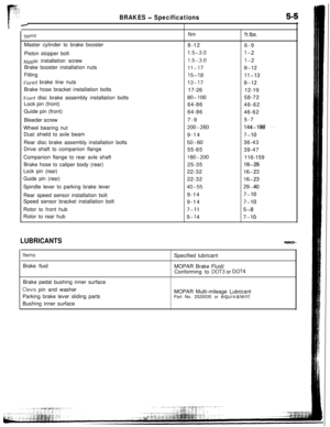
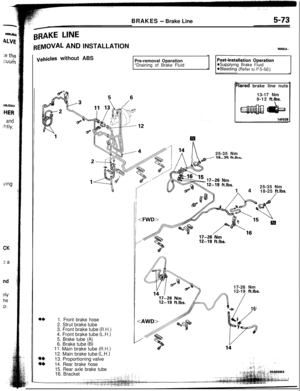
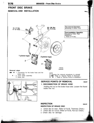
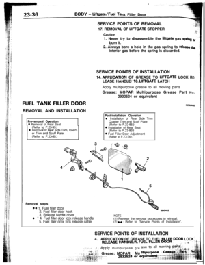
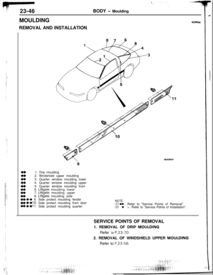
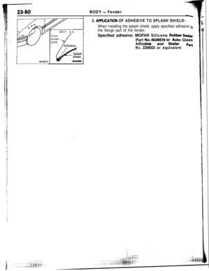
.+AR msc BRAKEREMOVAL AND INSTALLATION
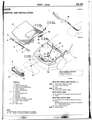
Pre-removal Operationl Draining of Brake Fluid
9-14 Nm7-10 ft.lbs.
50-60 Nm
36-43 ft.lbs.
/Post-installation Operation
*Supplying Brake Fluid
l Bleeding(Refer to P.5-50.)*Adjustment of Parking Brake Lever
Stroke
(Refer to P.5-48.)
200-260 Nm144-188 ft.lbs.13-17 Nm
9-12 ft.lbs.
/ -29-14
Nh7- 10 ftlbs.
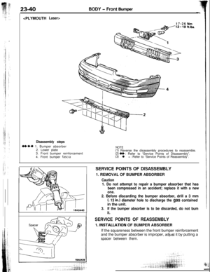
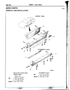
Removal steps
1. Parking brake cable connection
2. Brake hose connection
3. Rear brake assembly
4. Rear brake disc
5. Hubcap
l 6. Wheel bearing nut
14AO5747. Washer
8. Rear speed sensor bracket
9. Rear hub assembly14. Dust shieldI ‘: I
FyEeverse the removal procedures to reinstall.
(2) +* : Refer to “Service Points of Removal”.,,
(3) l + : Refer to “Service Points pt(4) m : Non-reusable parts:lpstallation
../ ‘E-w,,,
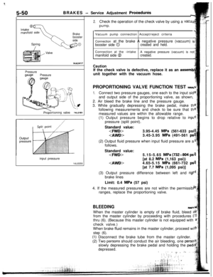
Page 28 of 57
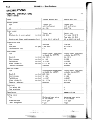
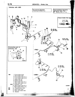
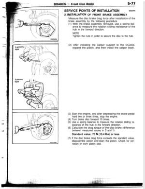
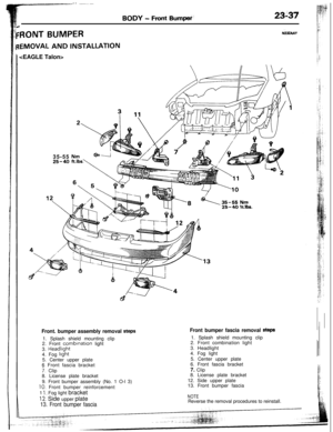
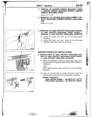
5-86
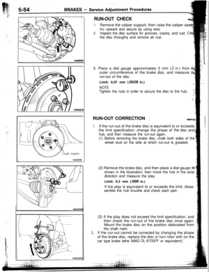
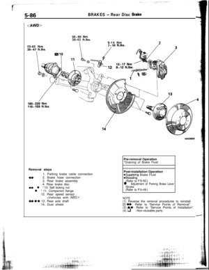
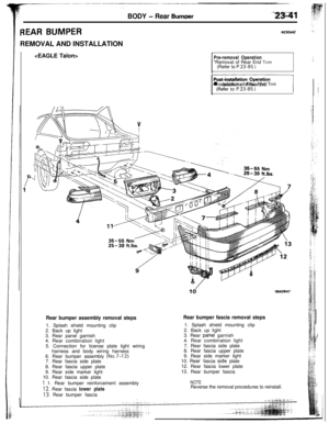
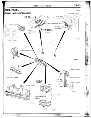
BRAKES - Rear Disc Btike55-65 Nm
50-60 Nm
36-43 ft.lbs.9-14 Nm
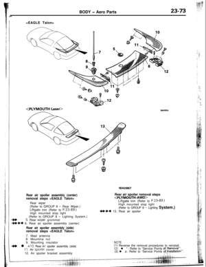
2Pre-removal Operation
*Draining of Brake Fluid
Removal steps
1. Parking brake cable connection
4*2. Brake hose connection
3. Rear brake assembly
4. Rear brake disc
+e l * 10. Self locking nutl * 11. Companion flange
12. Rear speed sensor
ABS>
*e ++ 13. Rear axle shaft
14. Dust shieldPost-installation Operation
@Supplying Brake Fluid@Bleeding(Refer to P.5-50.)l Adjustment of Parking Brake LeverStroke
(Refer to P.5-48.)
NOTE(1) Reverse the removal procedures to reinstall.
(2) +* : Refer to “Service Points of Removal”.
(3) I)+ : Refer to “Service Points of Installation”.
(4) q : Non-reusable parts
Page 29 of 57

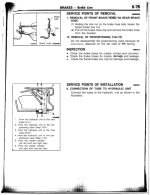
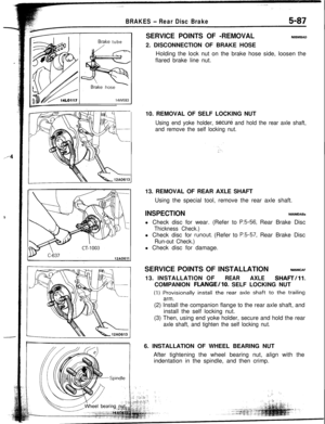
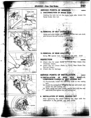
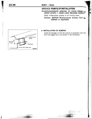
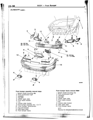
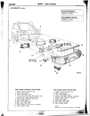
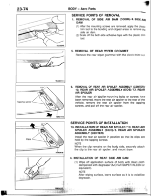
Brake tubeSERVICE POINTS OF -REMOVALNO5MBAD2. DISCONNECTION OF BRAKE HOSE
Holding the lock nut on the brake hose side, loosen the
flared brake line nut.
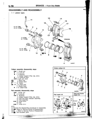
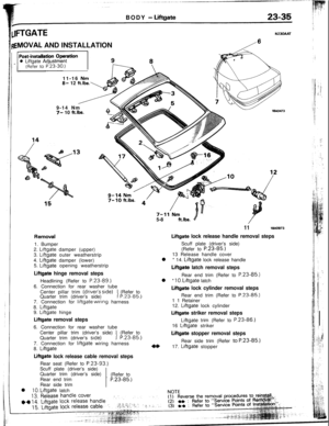
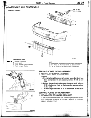
BRAKES - Rear Disc Brake5-8710. REMOVAL OF SELF LOCKING NUT
Using end yoke holder, secure and hold the rear axle shaft,
and remove the self locking nut.13. REMOVAL OF REAR AXLE SHAFT
Using the special tool, remove the rear axle shaft.
INSPECTIONNOSMDABal Check disc for wear. (Refer to
P.5-56, Rear Brake Disc
Thickness Check.)l Check disc for
runout. (Refer to P.5-57, Rear Brake Disc
Run-out Check.)l Check disc for damage.
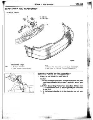
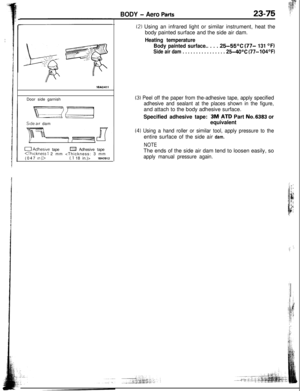
SERVICE POINTS OF INSTALLATION
NOBMCAF13. INSTALLATION OF
REARAXLESHAFTill.COMPANION
FLANGE/lo. SELF LOCKING NUT(1)
Provisionally install the rear axle shaft to the trailing
arm.(2) Install the companion flange to the rear axle shaft, and
install the self locking nut.
(3) Then, using end yoke holder, secure and hold the rear
axle shaft, and tighten the self locking nut.6. INSTALLATION OF WHEEL BEARING NUT
After tightening the wheel bearing nut, align with the
indentation in the spindle, and then crimp.
:. ‘.:,,
Page 30 of 57
axle shaft,
Usingthespecialtool; r:&.le shaft. :.;; -..s../ : i 3<.- Ef
Thickness Check.)
Run-out Check.)Check disc for damage.
Page 31 of 57
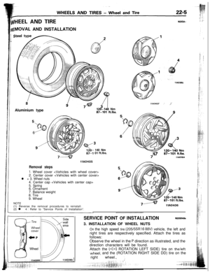
~~~HEEL AND TIREN22GA..
{EMOVAL AND INSTALLATION
Aluminium type
120-140 Nm87-101 ft.lbs.
6
140 Nm01 ft.lbs.
llA0405
Removal steps
I. Wheel cover
2. Center cover
l + 3. Wheel nuts4. Center cap
5. Spring6. Ornament
NOTE7. Balance weight
8. Tire
9. Wheel
(1) Reverse the removal procedures to reinstall.
(2) l 4
: Refer to “Service Points of Installation”.llA0366
llA0407,’ J’
7VA0364
llA0406
SERVICE POINT OF INSTALLATIONN22GDABs3. INSTALLATION OF WHEEL NUTS
On the high speed tire (205/55Rl6 88V) vehicle, the left andright tires are respectively specified. Attach the tires as
follows:
Observe the wheel in the
P direction as illustrated, and the
direction characters will be found.
Attach the
(44 ROTATION LEFT SIDE) tire on the leftwheel, and the (ROTATION RIGHT SIDE DD) tire on the
right wheel.,
1.
Page 32 of 57

INSTRUCTIONS FOR ALUMINUM TYPE
WHEELSN2zGFM
1. Aluminum is vulnerable to alkalies. If a vehicle
washing detergent has been used, or salt from
sea water or road chemicals has adhered, washthe vehicle as soon as possible. After washing
the vehicle, apply body or wheel wax to the
aluminum type wheels to prevent corrosion.
2. When cleaning the vehicle with steam, do not
direct steam onto the aluminum type wheels.
When tightening nuts for aluminum type
wheels, particularly observe the following:
(1) Cl;Zl;lsthe hub surface of aluminum type
(2) After finger-tightening wheel nuts, tighten
them to specifications.
(3) Do not use an impact wrench or push the
wrench by foot to tighten the wheel nuts.
(4) Do not apply oil to the threaded portions.
INSTRUCTIONS FOR TIRE CHAINS AND
SNOW TIRES
1.Use tire chains only on front wheels. Do not usetire chains on rear wheels.
2. When using snow tires, use them on all four
wheels for maneuverability and safety.
INSTRUCTIONS FOR COMPACT
TIRE
1. The compact spare tire is designed
space in the luggage compartment,
lighter weight makes it easier to use if
occurs.g
2.-- IThe following instructions for the compact spare .,z,tire should be observed.
i/(1) Check the inflation pressure after installing ii,the spare, and adjust to the specified
pres-..$i
sure.t’
(2) Avoid driving through automatic car washes
and over obstacles that could possiblyage the vehicle’s undercarriage. Because
the tire is smaller than the
original tire,
ground clearance is slightly reduced,
(3) The compact spare tire should not be
used: i5iS:on any other wheels, nor should standard
i;:?tires, snow tires, wheel covers or trim rings
Ibe used with the compact spare wheel. If.
1.;such use is attempted, damage to these
items or other vehicle components may
’
occur.
,i


Run-out Check.)Check disc for damage.")
