Page 17 of 57
 Holding the lock nut on the brake hose side, loosen theflared brake line nut.
(2) Pull off")
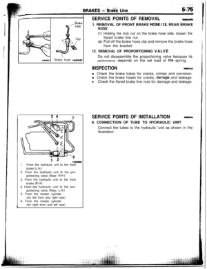
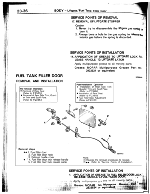
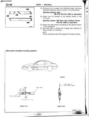
SERVICE POINTS OF REMOVAL
14w593Brake hose woo07
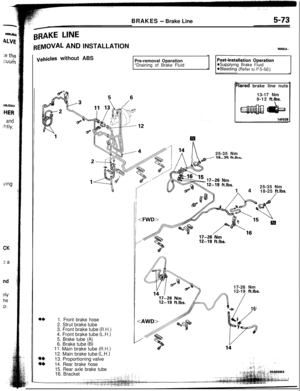
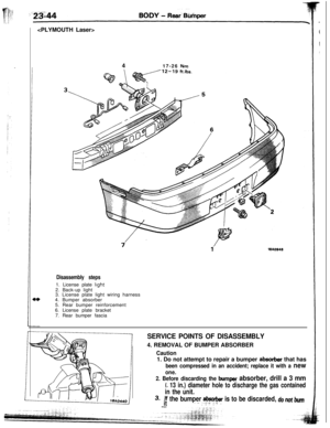
s 461. REMOVAL OF FRONT BRAKE
HOSE/13. REAR BRAKE
HOSE
(1) Holding the lock nut on the brake hose side, loosen theflared brake line nut.
(2) Pull off the brake hose clip and remove the brake hose
from the bracket.
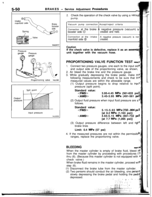
12. REMOVAL OF PROPORTIONING VALVEDo not disassemble the proportioning valve because its
performance depends on the set load of the spring.
INSPECTIONNo6KcMl Check the brake tubes for cracks, crimps and corrosion.
l Check the brake hoses for cracks,
damade and leakage.
lCheck the flared brake line nuts for damage and leakage.
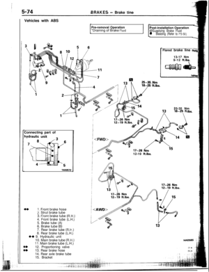
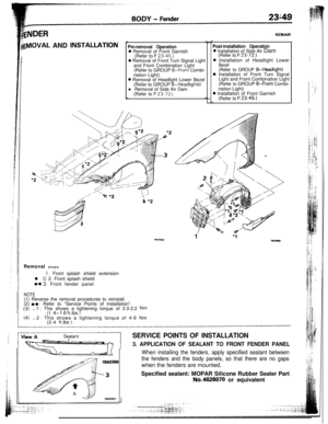
SERVICE POINTS OF INSTALLATIONNOSKOAJ9. CONNECTION OF TUBE TO HYDRAULIC UNIT
Connect the tubes to the hydraulic ‘unit as shown in the
illustration.
i 214AO5681.From the hydraulic unit to the front
brake
(L.H.)2. From the hydraulic unit to the pro-
portioning valve (Rear,
R.H.)3. From the hydraulic unit to the front
brake
(R.H.)4. From,the hydraulic unit to the pro-
portioning valve (Rear,
L.H.)5. From the master cylinder
(for left front and right rear)
6. From the master cylinder
(for right front and left rear)
Page 18 of 57
! -;-596
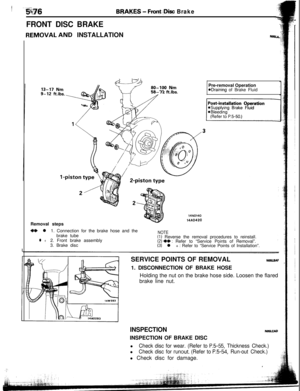
FRONT DISC BRAKE
Bf?Al$ES - Front.:,Diw Brake
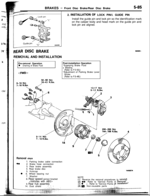
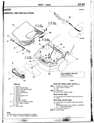
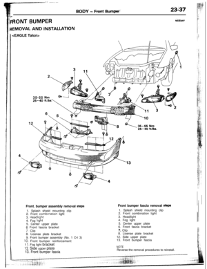
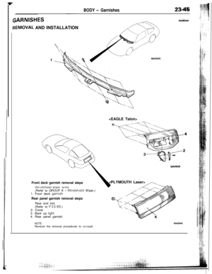
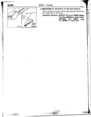
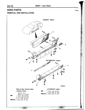
REMOVAL AND INSTALLATIONN=U.
3U- IL l-LIDS.Y-i A
14N014014A0420Pre-removal Operation
eDraining of Brake Fluid
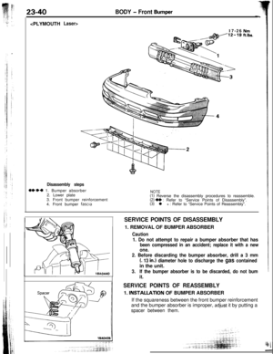
Removal steps
+e l1. Connection for the brake hose and the
brake tubeNOTE
l +2. Front brake assembly(1) Reverse the removal procedures to reinstall.
3. Brake disc(2) ++ : Refer to “Service Points of Removal”.(3) l + : Refer to “Service Points of Installation”.
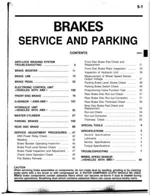
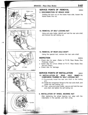
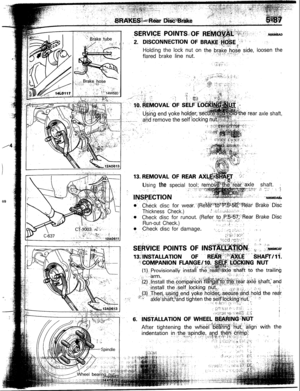
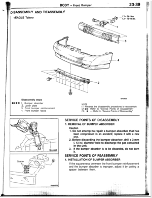
SERVICE POINTS OF REMOVAL
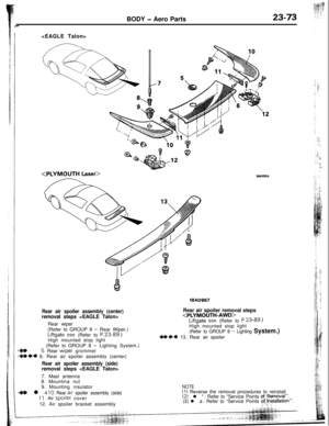
No5LsAF1. DISCONNECTION OF BRAKE HOSE
Holding the nut on the brake hose side. Loosen the flared
brake line nut.
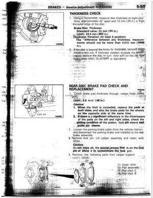
INSPECTIONNNiLCIDINSPECTION OF BRAKE DISC
l
Check disc for wear. (Refer to P.5-55, Thickness Check.)l
Check disc for runout. (Refer to P.5-54, Run-out Check.)l Check disc for damage.
Page 19 of 57
")
-
3AF
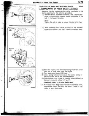
:dSERVICE POINTS OF INSTALLATION
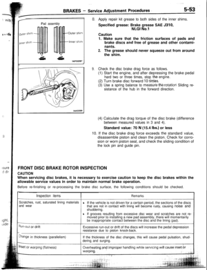
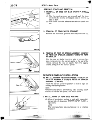
NOBLDAG2.
INSTILLATION OF FRONT BRAKE ASSEMBLY
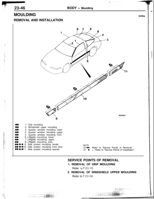
14AO399Measure the disc brake drag force after installation of the
brake assembly by the following procedure.(1) With the brake assembly removed, use a spring bal-
ance to measure the rotation sliding resistance of the
hub in the forward direction.
NOTE
Tighten the nuts in order to secure the disc to the hub.(2) After installing the caliper support to the knuckle,
expand the piston, and then install the caliper body.
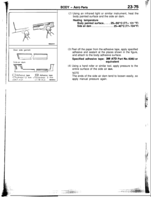
(3) Start the engine, and after depressing the brake pedal
hard two or three times, stop the engine.
(4) Turn brake disc forward 10 times.
(5) Use a spring balance to measure the rotation sliding re-
sistance of the hub in the forward direction.(6) Calculate the drag torque of the disc brake (difference
between measured values in 5 and 1).Standard value: 70
N (15.4 Ibs.) or less
(7) If the disc brake drag force exceeds the standard value,
disassemble piston and’clean the piston. Check for cor-
rosion or worn piston seal.
Page 20 of 57
-.
t
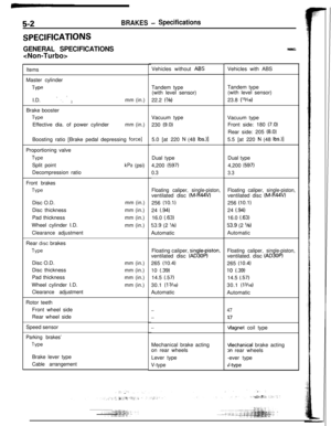
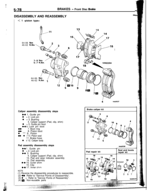
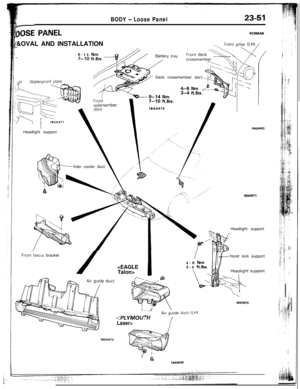
5-78BRAKES - Front Disc Bra&.iDISASSEMBLY AND REASSEMBLY
NO51
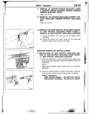
< 1 -piston type>
64-86
46-62
64-86
46-6216
/
w”! 14N0284
Caliper assembly disassembly steps
M 1. Guide pin
l + 2. Lock pin
l + 3. Bushing
4. Caliper support (Pad, clip, shim)
l + 5. Guide pin bootMI 6. Lock pin boot
**7. Boot ring4*8. Piston boot
l *** 9. Piston
+I) l * IO. Piston seal11. Brake hosel + 12. Caliper body
Pad assembly disassembly steps
e+ 1. Guide pin
l + 2. Lock pin*+ 3. Bushing4. Caliper support (Pad, clip, shim)
13. Pad and wear indicator assembly
14. Pad assembly
++ 15. Outer shim16. Clip
e+ 17. Inner shim
NOTE
(1) Reverse the disassembly procedures to reassemble.(2)
~~ : Refer to “Service Points of Disassembly”.(3) l + : Refer to “Service Points of Reassembly”.
(4) m : Non-reusable parts
1
i14AO537Brake caliper kit
Pad repair kitSeal and boots
repair kit
10 6
5’ 8 7
-.I.14AD54(
Page 21 of 57
 as a set.
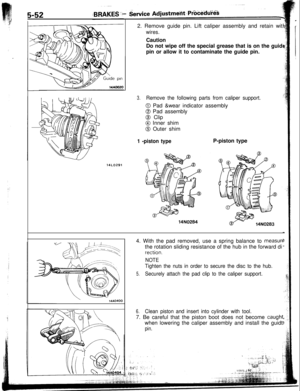
7. REMOVAL OF BOOT RING
Remove boot ring with f")
Boot. ring14KO541460054L
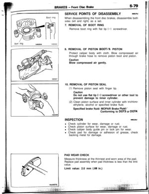
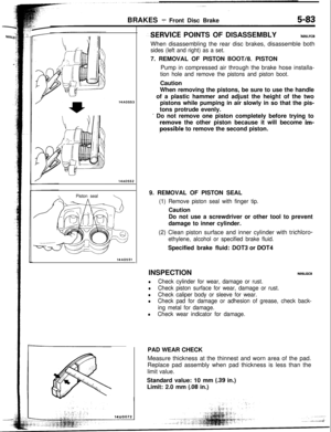
SERVICE POINTS OF DISASSEMBLYNOSLFAJWhen disassembling the front disc brakes, disassemble both
sides (left and right) as a set.
7. REMOVAL OF BOOT RING
Remove boot ring with flat tip (-1 screwdriver.
8. REMOVAL OF PISTON BOOT/g. PISTON
Protect caliper body with cloth. Blow compressed air
through brake hose to remove piston boot and piston.
CautionBlow compressed air gently.
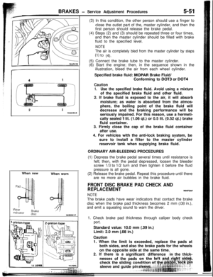
10. REMOVAL OF PISTON SEAL
(1) Remove piston seal with finger tip.
CautionDo not use flat tip
(-) screwdriver or other tool to
prevent damage to inner cylinder.
(2) Clean piston surface and inner cylinder with
trichloro-ethylene, alcohol or specified brake fluid.
Specified brake fluid: MOPAR Brake
Fluid/
Conforming to DOT3 or DOT4
INSPECTIONNOXGAJ
l Check cylinder for wear, damage or rust.
l Check piston surface for wear, damage or rust.
l Check caliper body guide pin or lock pin for wear.
l Check pad for damage or adhesion of grease, check
backing metal for damage.
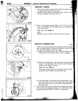
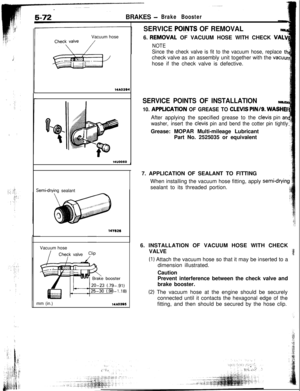
PAD WEAR CHECK
Measure thickness at the thinnest and worn area of the pad.
Replace pad assembly when pad thickness is less than the limit
value.Limit value: 2.0 mm
(.08 in.)
Page 22 of 57

----aI’-I
5-80BRAKES - Front Disc Brake
I-
Pad and wear
indicator assemblyPad assembly
Grease14FOO97
14KOIQPiston boot
’14KO70
Grease
L
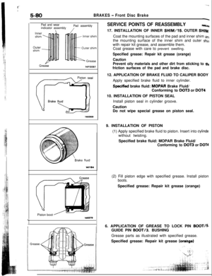
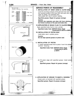
SERVICE POINTS OF REASSEMBLYWC17. INSTALLATION OF INNER
SHIM/15. OUTER SHIMCoat the mounting surfaces of the pad and inner shim
antthe mounting surface of the inner shim and outer
shinwith repair kit grease, and assemble them.
Coat grease with care to prevent swelling.
Specified grease: Repair kit grease (orange)
Caution
Prevent oily materials and other dirt from sticking to
tht
friction surfaces of the pad and brake disc.12. APPLICATION OF BRAKE FLUID TO CALIPER BODY
Apply specified brake fluid to inner cylinder.
Specified brake fluid: MDPAR Brake Fluid/
Conforming to DOT3 or
DOT410. INSTALLATION OF PISTON SEAL
Install piston seal in cylinder groove.
Caution
Do not wipe special grease on piston seal.
9. INSTALLATION OF PISTON
(1) Apply specified brake fluid to piston. Insert into
cylinde’without twisting.
Specified brake fluid: MOPAR Brake Fluid/
Conforming to DOT3 or DOT4(2) Fill piston edge with specified grease. Install piston
boots.Specified grease: Repair kit grease (orange)
6. APPLICATION OF GREASE TO LOCK PIN
BOOT/5GUIDE PIN BOOT/3. BUSHING
Grease parts as illustrated with specified grease.
Specified grease: Repair kit grease
(orange)
Page 23 of 57
Nosub
,Hlrq
m an
shii
to thl
ODY
l-4
hnde
jOT4
Iston
T/5.
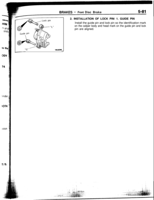
"G"- -14LO2942. INSTALLATION OF LOCK PIN/ 1. GUIDE PIN
Install the guide pin and lock pin so the identification mark
on the caliper body and head mark on the guide pin and lockpin are aligned.
BRAKES -Front Disc Brake5-81
Page 24 of 57
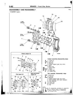
5-82BRAKES - Front Disc BrakeDISASSEMBLY AND REASSEMBLY
<2-piston type>
NOBLE..75 Nm
54 ft.lbs.
\
8Nm/6 ft.lbs.75 Nm
/
54 ft.lbs.Brake caliper kit
Pad repair kit
ISeal and boots
repair kit
6lEl/14N02664
Caliper assembly disassembly steps
l + 1. Guide pin
~~ 2. Lock pin
l 3. Bushing
4. Caliper support (pad, clip, shim)+4 5. Boot
6. Boot ring
4*7. Piston boot+e ++ 8. Piston** l + 9. Piston seall +I 0. Caliper body
Pad assembly disassembly steps
~~ 1. Guide pin
l + 2. Lock pinI)+ 3. Bushing
4. Caliper support (pad, clip, shim)
11. Pad assembly (with wear indicator)
12. Pad assembly
l +13. Outer shim
l 414. Inner shim15. ClipReverse the disassembly procedures to reassemble.
d*: Refer to “Service Points of Disassembly”.
l 4: Refer to “Service Points of Reassembly”.
‘:m: Non-reusable parts