Page 49 of 57
23-48BODY - Moulding
lBAOO55(3) Remove
backrng paper from adhesive tape, and applyspecified adhesive tape as shown in the illustration,
Specified adhesive tape:
3M ATD Part No. 6383 or equivalent
(4) Apply
specrfred sealant to the places shown in the
rllustratidn.
Specified sealant: 3M Super Fast Urethane PrimerPart No. 8608 or equivalent
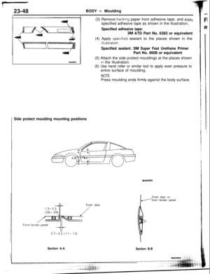
(5) Attach the side protect mouldings at the places shown
In the illustration.
(6) Use hand roller or similar tool to apply even pressure toentire surface of moulding.
NOTEPress moulding ends
f.irmly against the body surface.
Side protect moulding mounting positionsMA0400
Front doorFront door or
front fender panel
Section A-A
Section B-B
Page 50 of 57
0 Removal of Front Turn Signal Light
and Front Combination Light
(Refer to GROUP
8-Front Combi-
nation")
kNDER
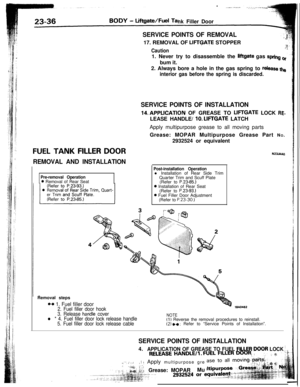
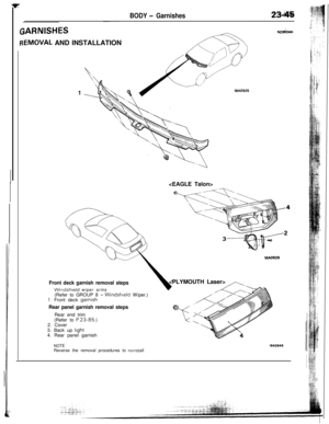
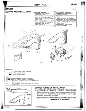
lgVlOVAL AND jNSTALLATIONPm-removal Operation0 Removal of Front Garnish
(Refer to P.23.45.)0 Removal of Front Turn Signal Light
and Front Combination Light
(Refer to GROUP
8-Front Combi-
nation Light)0 Removal of Headlight Lower Bezel
(Refer to GROUP 8-Headlights)
l Removal of Side Air Dam
(Refer to P.23.72
)
N23KAAT
Post-installation Operation0 Installation of Side Air Dam
(Refer to
P.23-72.)0 Installation of Headlight Lower
Bezel(Refer to GROUP 8-Headlight)0 Installation of Front Turn Signal
Light and Front Combination Light
(Refer to GROUP
8-Front Combi-
nation Light)0 Installation of Front Garnish
(Refer to
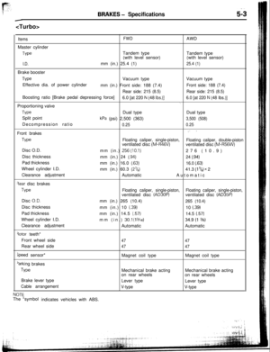
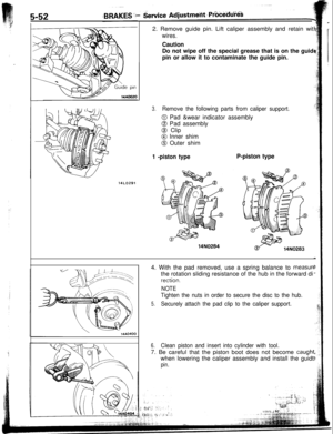
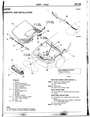
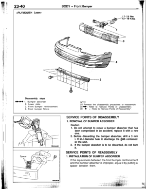
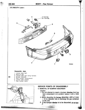
P.23-45.1Removal steps
1, Front splash shield extension
l C 2. Front splash shield
WC 3. Front fender panel
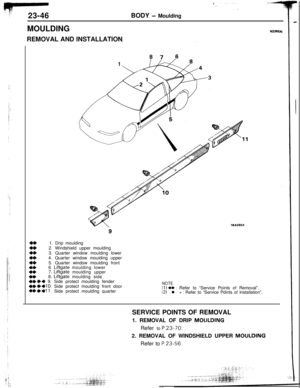
NOTE(1) Reverse the removal procedures to reinstall.
(2)
.4 : Refer to “Service Points of Installation”.(31l 1 : This shows a tightening torque of 2.0-2.2 Nm(1 .4-l .6 ft.lbs.1.(4)l 2 : This shows a tightening torque of 4-6 Nm
(2-4 ft.lbs.).
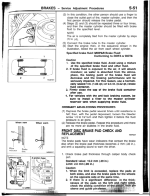
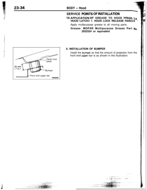
SERVICE POINTS OF INSTALLATION
3. APPLICATION OF SEALANT TO FRONT FENDER PANEL
When installing the fenders, apply specified sealant between
the fenders and the body panels, so that there are no gapswhen the fenders are mounted.
Specified sealant: MOPAR Silicone Rubber Sealer PartNo.4026070 or equivalent
Page 51 of 57
23-50BODY - Fender
1 16A0810
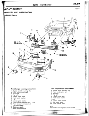
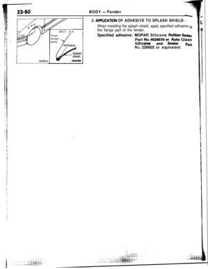
rSECT. A-A
Front
fender
panel
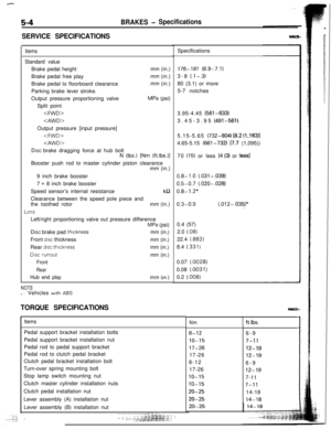
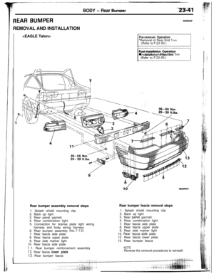
2. Al’PLlCATlON OF ADHESIVE TO SPLASH SHIELD- ._
When installing the splash shield, apply specified adhesive to
the flange part of the fender.
Specified adhesive: MOPAR Silicone Rubber SealerPart
No.402zWiO oket;F Glass
Adhesive
NO. 2299925 or equivalentPart
Page 52 of 57
*,i
bSE PANEL
BODY - Loose Panel23-51
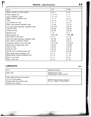
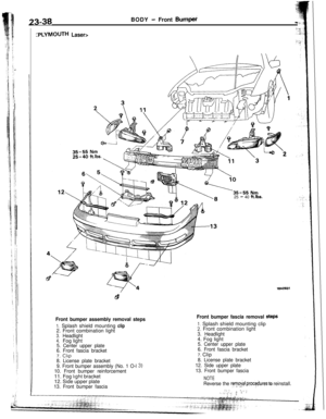
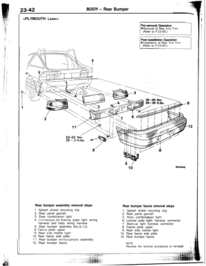
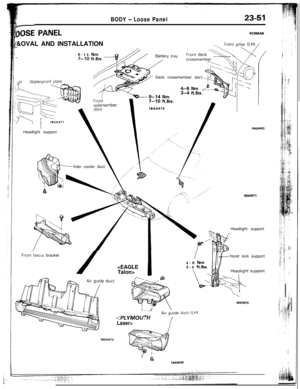
N23sAAK/&OVAL AND INSTALLATION
.-9-14
Nm.7-10 ft.k
Front pillar ILH) /Headlight support
Inter cooler duct
Front/fascia bracket
/crossmember
Deck crossmember sta
lSA0463
18AO971Headlight support
Talon>4-6
Nm3-4 ft.lbs.Hood lock support
WA0970
ISA0472
LT IVIUUIn
Laser>I
18AO939
Page 53 of 57
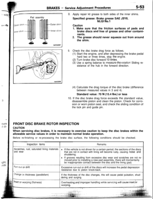
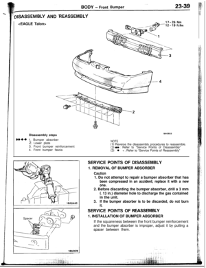
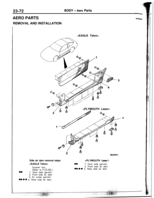
23-72BODY - Aero PartsAERO PARTS
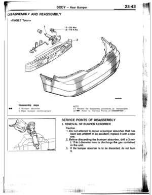
REMOVAL AND INSTALLATION
Side air dam removal steps
Quarter trim
4*(Refer to P.23-85.)1. Door side garnish
2. Front side air dam
3.
Air outlet garnish
We+ 4. Rear side air dam
Laser>
4*1. Door side garnish
2. Front side air dam
+I)** 4. Rear side air dam4
Page 54 of 57
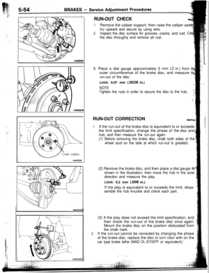
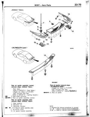
BODY - Aero Parts23-73
18A0967
Rear air spoiler assembly (center)removal steps Rear wiper
(Refer to GROUP 8
- Rear Wiper.)Liftgate trim (Refer to
P.23-89.)High mounted stop light
_ (Refer to GROUP 8 - Lighting System.)
(I*5. Rear wiper grommet
+I)*4 6. Rear air spoiler assembly (center)
Rear air spoiler assembly (side)removal steps 7. Mast antenna
8. Mountina nut
Rear air spoiler removal stepsLiftgate trim (Refer to P.2389.)High mounted stop light
(Refer to GROUP 8 - Lighting System.)
4* *4 13. Rear air spoiler
9. Mounting insulator
@ l 4 10. Rear air spoiler assembly (side)11, Air spooler cover
12. Air spoiler bracket assembly
NOTE(1) Reverse the removal procedures to reinstall.(2) l * : Refer to “Service Points of,Removal”.(3) l a : Refer to “Service Points of! kistallatron”.
, i. ::
Page 55 of 57
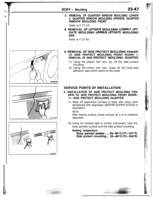
/4. SIDE AIRDAM
(1) After the mounting screws are removed, apply the plastic
trim tool to the bonding and")
I
23-74BODY - Aero Parts
\18AQ245
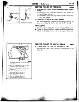
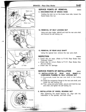
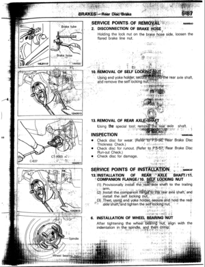
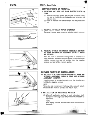
-ISERVICE POINTS OF REMOVAL1. REMOVAL OF SIDE AIR DAM
(DOOR)/4. SIDE AIRDAM
(1) After the mounting screws are removed, apply the plastic
trim tool to the bonding and clipped areas to remove the
side air dam.
(2) Scale off the both-side adhesive tape with the plastic trim
tool.
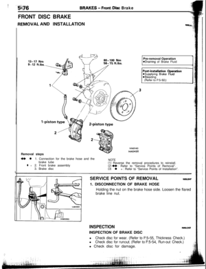
16AQ414J5. REMOVAL OF REAR WIPER GROMMET
Remove the rear wiper grommet with the
plastlc trim tool.
6.REMOVAL OF REAR AIR SPOILER ASSEMBLY (CENTER)/10. REAR AIR SPOILER ASSEMBLY (SIDE)/13. REAR
AIR SPOILERAfter the rear air’s’poiler mounting bolts or screws
hav2been removed, move the rear air spoiler to the rear of the
vehicle, remove the rear air spoiler from the tapping
screws, and pull off the rear air spoiler.
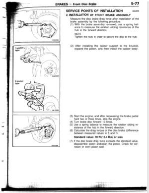
SERVICE POINTS OF INSTALLATION
13. INSTALLATION OF REAR AIR
SPOILER/lo. REAR AIR
SPOILER ASSEMBLY (SIDE)/G. REAR AIR SPOILER
ASSEMBLY (CENTER)
Install the rear air spoiler in position so that its clips are
held by the tapping screws.
NOTEWhen the clip remains on the body side, securely attach
the clip to the rear air spoiler, and mount
them.4. INSTALLATION OF REAR SIDE AIR DAM
(1) Wipe off application surface of body with clean cloth
dampened with degreaser
(MOPAR SUPER KLEEN or
equivalent).
NOTEAfter wiping surface, leave surface as it is to volatilize
degreaser.
Page 56 of 57
BODY - Aero P&s23-75 ‘!:j:
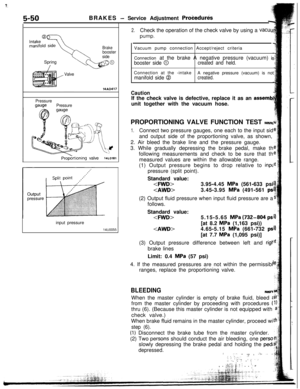
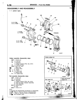
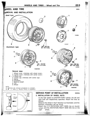
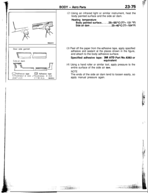
18A0411Door side garnishSide air dam
0 Adhesive tapea Adhesive tape(Thickness 1 2 mm
(047 In )>(.l 18 in.)>18A0912
(2) Using an infrared light or similar instrument, heat the
body painted surface and the side air dam.
Heating temperature
Body painted surface.. . . .
25-55OC (77- 131 OFI
Side air dam . . . . . . . . . . . . . . . . 25-40°C (77-104OF)
(3) Peel off the paper from the-adhesive tape, apply specified
adhesive and sealant at the places shown in the figure,and attach to the body adhesive surface.
Specified adhesive tape:
-3M. ATD Part No.6383 or
equivalent
(4) Using a hand roller or similar tool, apply pressure to theentire surface of the side air dam.
NOTEThe ends of the side air dam tend to loosen easily, so
apply manual pressure again.
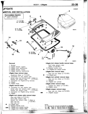
 Remove
backrng paper from adhesive tape, and applyspecified adhesive tape as shown in the illustration,
Specified adhesive tape:
3M ATD Part No. 6383 or equivalent
(4)")

 /Headlight support
Inter cooler duct
Front/fascia bracket
/crossmember
Deck crossmember sta")
1. Door side garnish
2. Front side ai")
removal steps <EAGLE Talon>Rear wiper
(Refer to GROUP 8
- Rear Wiper.)Liftgate trim (Refer to
P.23-89.)High mounted stop")
>(.l 18 in.)>18A0912
(2) Using an infrared light or similar")