Page 9 of 57
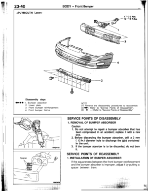
 In this condition, the other per")
BRAKES - Service Adjustment Procedures5-51
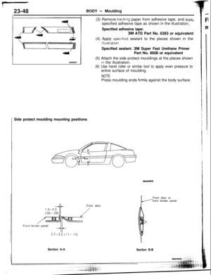
2314A0454When new
When worn14G0017
1
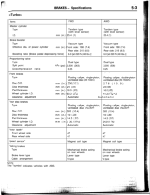
14 LO169check the sliding coWsTm~3..“.W% ,Y :sleeve and guide pin-~I ._. ;;:i ‘.(3) In this condition, the other person should use a finger to
close the outlet part of the, master cylinder, and then the
first person should release the brake pedal.
(4) Steps (2) and (3) should be repeated three or four times,
and then the master cylinder should be filled with brake
fluid to the specified level.
NOTE
The air is completely bled from the master cylinder by steps
(1) to (4).
(5) Connect the brake tube to the master cylinder.
(6) Start the engine; then, in the sequence shown in the
illustration, bleed the air from each wheel cylinder.
Specified brake fluid: MOPAR Brake Fluid/
Conforming to
DOT3 or DOT4
Caution
1.Use the specified brake fluid. Avoid using a mixtureof the specified brake fluid and other fluid.
2. If brake fluid is exposed to the air, it will absorb
moisture; as water is absorbed from the atmos-
phere, the boiling point of the brake fluid will
decrease and the braking performance will be
seriously impaired. For this reason, use a hermeti-
cally sealed
1 lit. (1.06 qt.) or 0.5 lit. (0.52 qt.) brake
fluid container.
3. Firmly close the cap of the brake fluid container
after use.
4. For vehicles with the anti-lock braking system, be
sure to install a filter to the master cylinder
reservoir tank when supplying brake fluid.
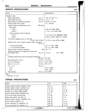
ORDINARY AIR-BLEEDING PROCEDURES
(1) Depress the brake pedal several times until resistance is
felt; then, with the pedal depressed, loosen the bleeder
screw
l/3 to l/2 turn and then tighten it before the fluid
pressure is all gone.
(2) Release the brake pedal. Repeat this procedure until there
are no more air bubbles in the brake fluid.
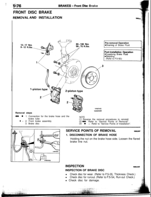
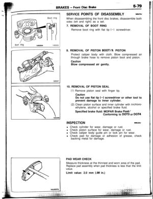
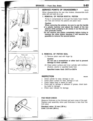
FRONT DISC BRAKE PAD CHECK AND
REPLACEMENTN05FOAF
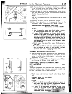
NOTEThe brake pads have wear indicators that contact the brake
disc when the brake pad thickness becomes 2 mm
(.08 in.),
and emit a squealing sound to warn the driver.1. Check brake pad thickness through caliper body check
port.Standard value: 10.0 mm
(.39 in.)
Limit: 2.0 mm
(.08 in.)
Caution
1. When the limit is exceeded, replace the pads at
both sides, and also the brake pads for the wheels
on the opposite side at the same time.
2. If there is a
significant difference
.in the thick-
nesses of the pads
Page 10 of 57
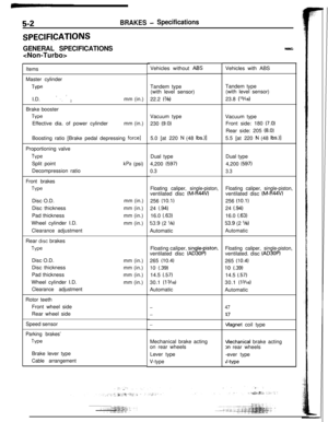
5-52
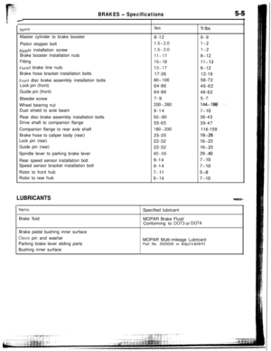
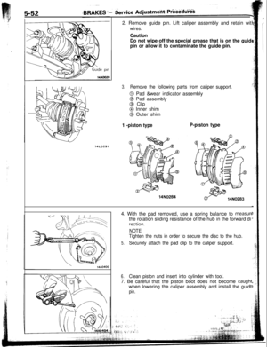
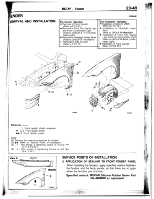
14LO2912. Remove guide pin. Lift caliper assembly and retain wit
wires.Caution
Do not wipe off the special grease that is on the guid
pin or allow it to contaminate the guide pin.
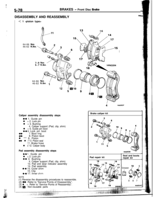
3.Remove the following parts from caliper support.
0 Pad &wear indicator assembly
0 Pad assembly
@ Clip
@I Inner shim
@ Outer shim
1 -piston type14N0284P-piston type
\14AO4004. With the pad removed, use a spring balance to
measurethe rotation sliding resistance of the hub in the forward di
rection.
NOTE
Tighten the nuts in order to secure the disc to the hub.
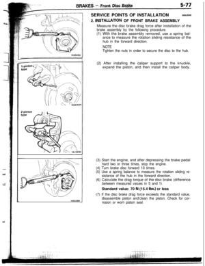
5.Securely attach the pad clip to the caliper support.
6.Clean piston and insert into cylinder with tool.7. Be careful that the piston boot does not become
caughlwhen lowering the caliper assembly and install the guidt
pin.
Page 11 of 57

guiisur
dd
lght
clidc
Pad assembly
luter shim
nner shim
43l a14FOO97
14A0399
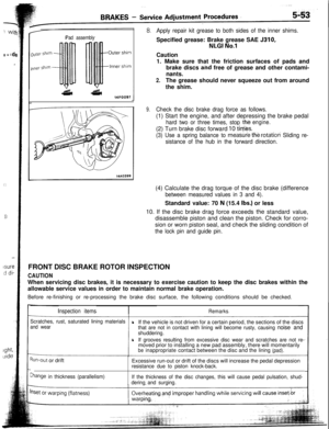
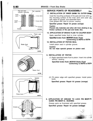
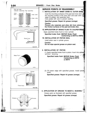
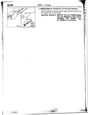
Apply repair kit grease to both sides of the inner shims.Specified grease: Brake grease SAE 5310,
NLGI No.1Caution
1. Make sure that the friction surfaces of pads and
brake discs and free of grease and other contami-
nants.
2.The grease should never squeeze out from around
the shim.
9.Check the disc brake drag force as follows.(1) Start the engine, and after depressing the brake pedal
hard two or three times, stop the(2) Turn brake disc forward
10 tie&.
engine.
(3) Use a spring balance to meastiie fh-e rotation Sliding re-
sistance of the hub in the forward direction.(4) Calculate the drag torque of the disc brake (difference
between measured values in 3 and 4).Standard value: 70
N (15.4 Ibs.) or less
10. If the disc brake drag force exceeds
tlie standard value,
disassemble piston and clean the piston. Check for corro-
sion or worn piston seal, and check the sliding condition of
the lock pin and guide pin.FRONT DISC BRAKE ROTOR INSPECTION
CAUTIONWhen servicing disc brakes, it is necessary to exercise caution to keep the disc brakes within the
allowable service values in order to maintain normal brake operation.
Before re-finishing or re-processing the brake disc surface, the following conditions should be checked.
Inspection itemsRemarks
Scratches, rust, saturated lining materials
and wearlIf the vehicle is not driven for a certain period, the sections of the discsthat are not in contact with lining will become rusty, causing noise and
shuddering.
lIf grooves resulting from excessive disc wear and scratches are not re-moved prior to installing a new pad assembly, there will momentarily
beinappropriatecontact between the disc and thelining(pad).
Run-out or drift
Ehange in thickness (parallelism)Excessive run-out or drift of the discs will increase the pedal depression
resistance due to piston knock-back.
If the thickness of the disc changes, this will cause pedal pulsation, shud-
deringand surging.
Page 12 of 57

14A0391
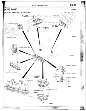
RUN-OUT CHECK
1.Remove the caliper support; then raise the caliper ass
bly upward and secure by using wire.
2.Inspect the disc surface for grooves, cracks, and rust. Cl
the disc throughly and remove all rust.3. Place a dial gauge approximately 5 mm
(.2 in.) from thiouter circumference of the brake disc, and measure
tt$
run-out of the disc._iLimit: 0.07 mm
(.0028 in.)-2
NOTE
Tighten the nuts in order to secure the disc to the hub..‘l;i,!
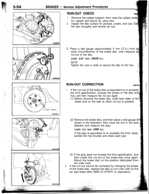
..,;RUN-OUT CORRECTION
NOSFTAB
1.If the run-out of the brake disc is equivalent to or exceeds
the limit specification, change the phase of
the disc and
hub, and then measure the run-out again.
(1) Before removing the brake disc, chalk both sides of the
wheel stud on the side at which run-out is greatest.(2) Remove the brake disc, and then place a dial gauge
2s
shown in the illustration; then move the hub in the axial
direction and measure the play.Limit: 0.2 mm
(.008 in.)
If the play is equivalent to or exceeds the limit, disas-
semble the hub knuckle and check each part.
2.(3) If the play does not exceed the limit specification, and
then check the run-out of the brake disc once again.
Mount the brake disc on the position dislocated from
the chalk mark.If the run-out cannot be corrected by changing the phase
of the brake disc, replace the disc or turn rotor with on the
car type brake lathe (MAD DL-8700PF or equivalent).’
.,“, . . . -..
Page 13 of 57
 in f,r$,m;,
i theo")
: : :.. t,:...!b
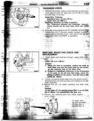
THl,~,KNES~i;CHECK, .‘i.- _d--.-.--.
1: ‘Using $.$i,crometer, measure disc thickness at eight posi- I
tions;:‘.@‘proximately 45” apart and 10 mm (.39 in.) in f,r$,m;,
i theouter’edge of the disc.‘I
+ Brbke.Disc Thickness..!+@Card value: 24 mm
(94 in.)
i,,~~~:-~4!-~~~t;:22.4 mm (.882 in.)
: ,aThrckness Variation (At least 8 position)
_ The ‘*difference between any thickness. measure-
ments should not be more than 0.015 mm
(.0006:
in.).,,7.9’-,... .J .
: .A12fi: If~thei;di& is beyond t& Jim@ for thickneT.%, ‘ie’mdv.,.
one. If thickness variation exceeds theace the:disc”or turn. rotor with on the.
(MAD, DL-87OOPF or equivalent).-
;_:.j ::!‘_, Ii..;, ‘I
t&;&C BRAKE PAD CHECK AND
., . .:L”” cn:
,.,1. ~:“ch&ii -brake pad thickness through, caliper body$%ck.~:?;{&:?p., d ii,; ,i..i; I&+# ~4:‘ ” :’/I..: “j.. .
~~Tl$$$‘~&b mm (08 cn.)
-.‘-‘: (~~#&q,,I,.:: y;./.
C&&ion”,- ‘-, -, iii,,, I.“‘?,t
--. +-When the limit is exceeded, replace the pad&at-:
,--both&sides, and also the brake pads for the wheels
onth-e opposite side at the same time.&.Jf,tb@re is a
signjfjcant difference in the thicknesses
of the pads on the left and right sides, check the
A.J. :%!idi,~g!~ondStion.of the piston, ‘lock p,in sleeve ;a,$$
f * ,midq py I sleye._, ,: .’ i.. . ii’.
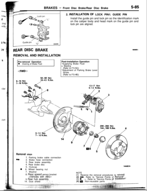
2.Loosen the parking brake cable (from the vehicle interior),
an$dis.co-nnect the parking brake end installed to the rearI II Iorake,. assemory.3.
f5$_move.,lock pin. Lift caliper assembly and retain ‘&h,
yps..,(y&on,DO
r$$v$e off. the stiecial!.grease. that’ is on the &ckpi”
cii’@!fow it to..c,ontait;inate tl;
,,
f :.,3-:: ” ,, ” -_.__ _, .“_,./‘7,.< :$, ~. . 6
Page 14 of 57

14AO395
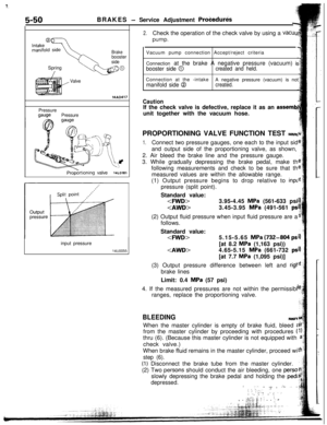
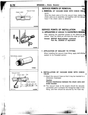
SERVICE PO@JTS OF REMOVALNocm6.
REM&AL OF VACUUM HOSE WITH CHECK VA+
NOTE
Since the c")
BRAKES -Brake BoosterVacuum hose
14AO39414u0050Semidrvina sealant
141626Vacuum hose
IChevk valve
mm (in.)
14AO395
SERVICE PO@JTS OF REMOVALNocm6.
REM&AL OF VACUUM HOSE WITH CHECK VA+
NOTE
Since the check valve is fit to the vacuum hose, replace thcheck valve as an assembly unit together with the
vacuurhose if the check valve is defective.
SERVICE POINTS OF INSTALLATION
10. APPLDJTION OF GREASE TO CLEVIS PIN/g. WASHEIAfter applying the specified grease to the
clevis pin an
washer, insert the
cievis pin and bend the cotter pin tightlyGrease: MOPAR Multi-mileage Lubricant
Part No. 2525035 or equivalent
7. APPLICATION OF SEALANT TO FITTING
When installing the vacuum hose fitting, apply
semi-cfryin!sealant to its threaded portion.
6. INSTALLATION OF VACUUM HOSE WITH CHECK
VALVE
(1) Attach the vacuum hose so that it may be inserted to a
dimension illustrated.
Caution
Prevent interference between the check valve and
brake booster.
(2) The vacuum hose at the engine should be securely
connected until it contacts the hexagonal edge of the
fitting, and then should be secured by the hose clip.
Page 15 of 57
N0sJa
4LVI
:e the
cuu<
‘=JD4\
;HER
and
!htly.
Wg
CK3a
nd
3ly
he
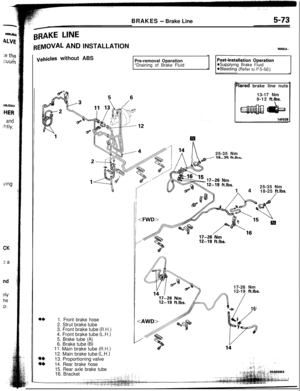
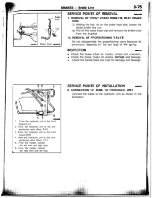
P.BRAKES
- Brake Line
BRAKE LINE
REMOVAL AND INSTALLATIONNOSKA--
1. Front brake hose2. Strut brake tube
3. Front brake tube
(R.H.)4. Front brake tube
(L.H.)5. Brake tube (A)6. Brake tube (B)11. Main brake tube (R.H.)12. Main brake tube
(L.H.)13. Proportioning valve
14. Rear brake hose
15. Rear axle brake tube
._-
Ill
n25-35 NmI 111-7G f-t Ihr:lared brake line nuts
13-17 Nm
9-12
ftlbs.
vehicles without ABS
Pre-removal Operation
*Draining of Brake Fluid
1425-35 Nm
18-25
ft.lbs.17-26 Nm
12-19
ft.lbs.
+1616. Bracket
Page 16 of 57
a-.
i.-J
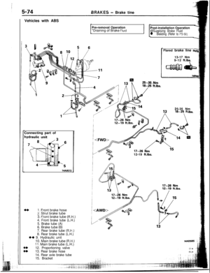
5-74BRAKES- Brake tine
Vehicles with ABS
Pre-removal Operation
*Draining of Brake
Fluid
,“iPost-installation OperationA
@Supplying Brake Fluid1
l Bleeding (Refer to P.5-50.)
-Connecting part of
14AO572
I. Front brake hose2. Strut brake tube- -25-35 Nm
Ibs.12-19
ft.lbs.Flared brake line
ns13-17 Nm
9-12
ftlbs.
15. Bracket3.
f-ront brake tube (R.H.)
4. Front brake tube (L.H.)
5. Brake tube (A)6. Brake tube
(B)7. Rear brake tube (R.H.)
8. Rear brake tube (L.H.)I)+ 9. Hydraulic unit
10. Main brake tube
(R.H.)11. Main brake tube (L.H.)
::
12. Proportioning valve
13. Rear brake hose
14. Rear axle brake tube
14AO585 ;

4.")

-Connecting pa")