Page 41 of 57
23-40BODY - Front Buripr
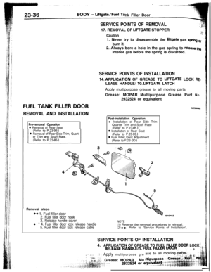
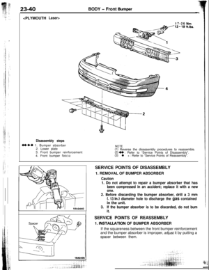
Laser>17-26
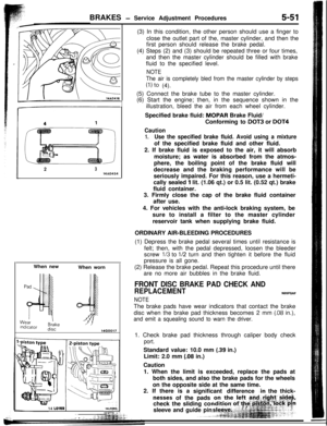
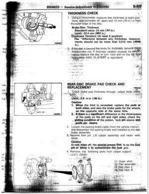
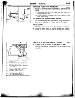
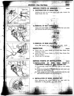
Disassembly steps
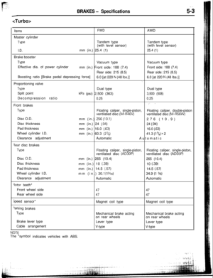
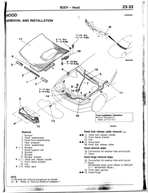
WI)* 1. Bumper absorber
2. Lower plate
3. Front bumper reinforcement
4. Front bumper
fascia
NOTE(1) Reverse the disassembly procedures to reassemble.(2) W : Refer to “Service Points of Disassembly”.(3) l + : Refer to “Service Points of Reassembly”.
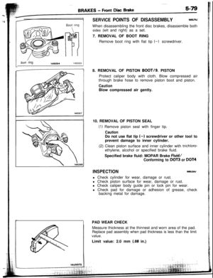
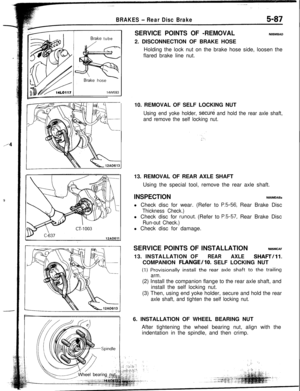
SERVICE POINTS OF DISASSEMBLY1. REMOVAL OF BUMPER ABSORBER
Caution
1. Do not attempt to repair a bumper absorber that has
been compressed in an accident; replace it with a new
one.
2. Before discarding the bumper absorber, drill a 3 mm
(. 13 in.) diameter hole to discharge the gas containedin the unit.
3.If the bumper absorber is to be discarded, do not bum
it.
SERVICE POINTS OF REASSEMBLY1.
INSTALLATiON OF BUMPER ABSORBER
If the squareness between the front bumper reinforcement
and the bumper absorber is improper,
adjusj it by putting a
spacer between them.
Page 42 of 57
BODY - Rear Burn-r
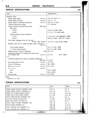
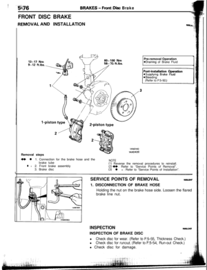
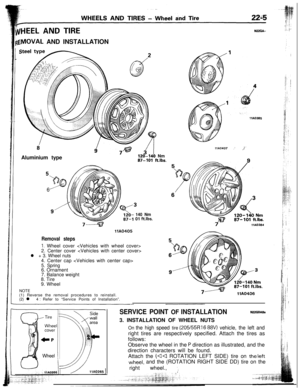
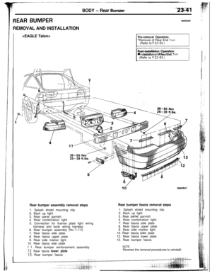
REAR BUMPERREMOVAL AND INSTALLATION
N23iiUU
Pre-removal Operation*Removal of Rear End Trim(Refer to P.23.85.)
nl lnstallatron of Rear End Trim
td19AO947
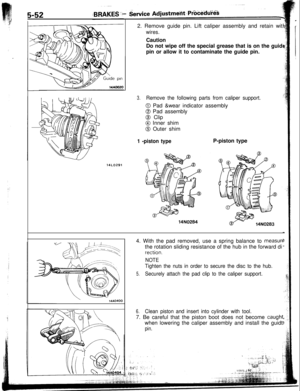
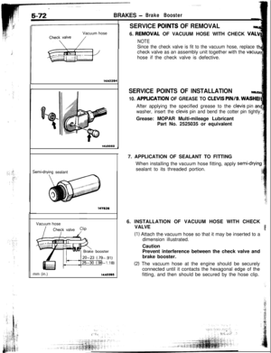
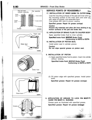
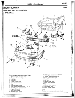
Rear bumper assembly removal steps1. Splash shield mounting clip
2. Back up light
3. Rear panel garnish
4. Rear combination light
5. Connection for license plate light wiring
harness and body wiring harness
6. Rear bumper assembly
(No.7-12)7. Rear fascia side plate
8. Rear fascia upper plate
9. Rear side marker light
10. Rear fascia side plate
1 1. Rear bumper reinforcement assembly
12. Rear fascia lower plate
13. Rear bumper fascia
Rear bumper fascia removal steps1. Splash shield mounting clip
2. Back up light
3. Rear pahel garnish
4. Rear combination light
7. Rear fascia side plate
8. Rear fascia upper plate
9. Rear side marker light
10.
Rear. fascia s,ide plate
12. Rear fascia lower plate
13. Rear bumper fascia
NOTEReverse the removal procedures to reinstall.
Page 43 of 57
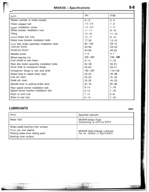
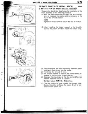
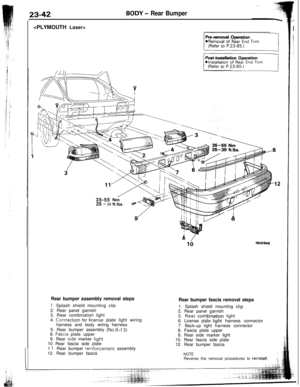
23-42,BODY - Rear Bumper
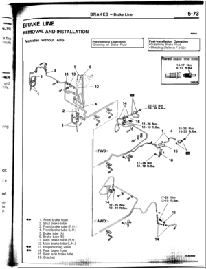
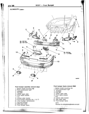
35-55
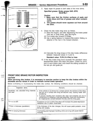
Nni25 - 39 ft.lbs.
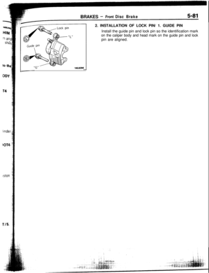
Rear bumper assembly removal steps
1. Splash shield mounting clip
2. Rear panel garnish
3. Rear combination light
4. Connectron for
license plate light wiring
harness and body wiring harness
5. Rear bumper assembly
(No.8-13)8. Fascra plate upper
9. Rear side marker light10 Rear fascia side plate
1
1. Rear bumper reinforcement assembly
12. Rear bumper fascia
18A0948
Rear bumper fascia removal steps1. Splash shield mounting
clip2. Rear panel garnish
3. Rear
combinatjon light
6. License plate light harness connector
7. Back-up light harness connector
8. Fascia plate upper
9. Rear side marker light
10. Rear fascia side plate
12. Rear bumper fascia
NOTEReverse the removal procedures to reinstal,l.
Page 44 of 57
-BODY
- Rear Bumper
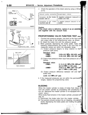
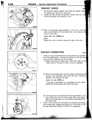
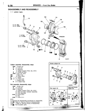
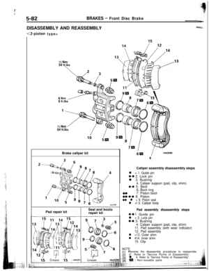
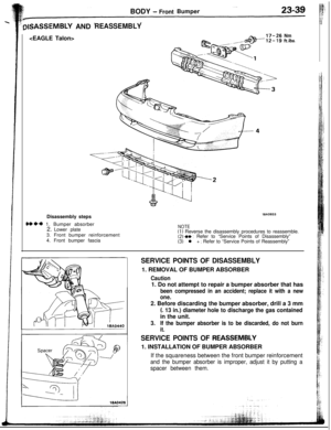
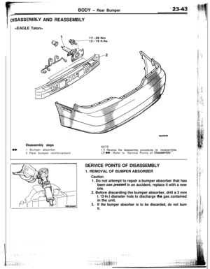
DISASSEMBLY AND REASSEMBLY
Disassembly steps1 Bumper absorber
2 Rear bumper reinforcementNOTE(1) Reverse the disassembly procedures to reassemble.(2)
++ : Refer to “Service Points of Disassembly”.
SERVICE POINTS OF DISASSEMBLY1. REMOVAL OF BUMPER ABSORBER
Caution1. Do not attempt to repair a bumper absorber that has
been con:pressed in an accident; replace it with a new
one.2. Before discarding the bumper absorber, drill a 3 mm
(. 13 in.1 diameter hole to discharge thii gas containedin the unit.
3.If the bumper absorber is to be discarded, do not bum
it.
Page 45 of 57
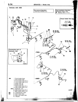
417-26 Nm
18AO948
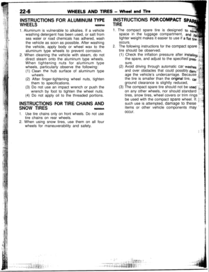
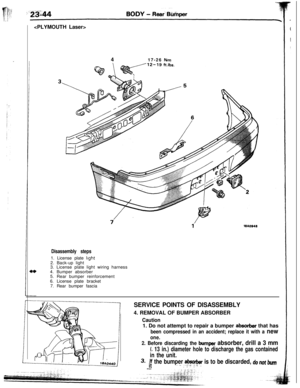
Disassembly steps1. License plate
light2. Back-up light
3. License plate light wiring harness
4. Bumper absorber
5. Rear bumper reinforcement
6. License plate bracket
7. Rear bumper fascia
SERVICE POINTS OF DISASSEMBLY4. REMOVAL OF BUMPER ABSORBER
2. Before discarding the bumper absorber, drill a 3 mm
L 13 in.) diameter hole to discharge the gas contained
in the unit.
3.If the bumper absorber is to be discarded, do not bumit,. _..2;+ i_.I/~.L I
Caution1. Do not attempt to repair a bumper
absorber that has
been compressed in an accident; replace it with a new
one.
Page 46 of 57
BODY - Garnishes-~
ZARNISHESN23dDAH
IEMOVAL AND INSTALLATION
18Ad925
18AO929
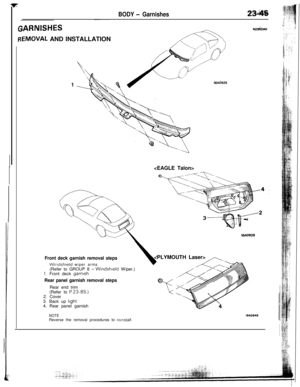
Front deck garnish removal steps
WIndshield wiper arms
(Refer to GROUP 8 -Windshield Wiper.)1. Front deck garnish
Rear panel garnish removal stepsRear end trim
(Refer to
P.23-85.)2. Cover
3. Back up
light4. Rear panel garnish
,,-..,.,-
E
“c
NOTEReverse the removal procedures to relnstall.16AOS45
Page 47 of 57
23-46BODY - Moulding
MOULDING
REMOVAL AND INSTALLATION
WA0954
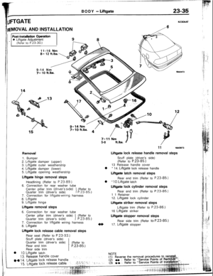
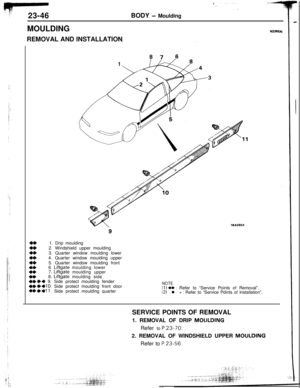
N23REIU1. Drip moulding
2. Windshield upper moulding
z3. Quarter window moulding lower
4. Quarter window moulding upper
4*5. Quarter window moulding front
:+’6.
Liftgate moulding lower
7. Liftgate moulding upper
4*8. Liftgate moulding side+e+* 9. Side protect moulding fender4+1)+10. Side protect moulding front door4**+11. Side protect moulding quarter
NOTE(1) a* : Refer to “Service Points of Removal”.12) l + : Refer to “Service Pdints of Installation”.
SERVICE POINTS OF REMOVAL
1. REMOVAL OF DRIP MOULDING
Refer to
P.23-70.2. REMOVAL OF WINDSHIELD UPPER MOULDING
Refer to
P.23-56.
Page 48 of 57

BODY - Moulding23-47
?8UO387
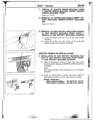
3.REMOVAL OF QUARTER WINDOW MOULDING LOWER/
4. QUARTER WINDOW MOULDING UPPER/B. QUARTER
WINDOW MOULDING FRONTRefer to P.23-59.
6. REMOVAL OF
LIFTGATE MOULDING LOWER17. LIFT-GATE MOULDING
UPPER/8. LIFTGATE MOULDING
SIDERefer to P.23-60.
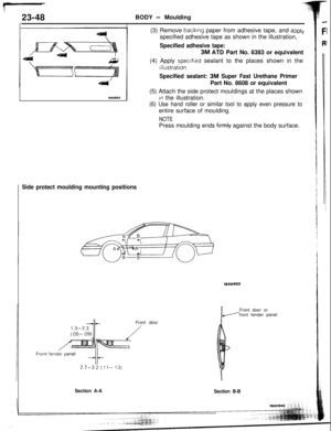
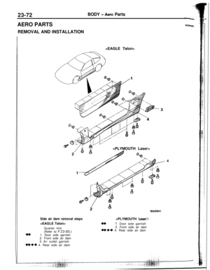
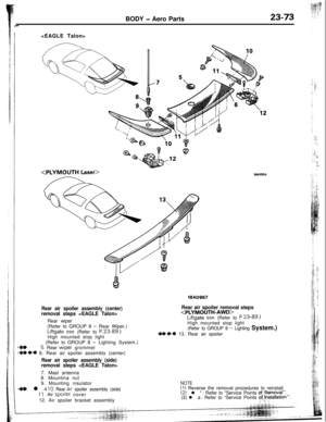
9. REMOVAL OF SIDE PROTECT MOULDING FENDER/
10. SIDE PROTECT MOULDING FRONT DOOR/l 1.
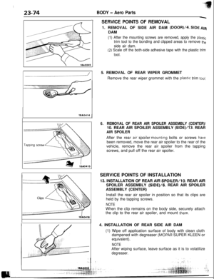
REMOVAL OF SIDE PROTECT MOULDING QUARTER(1) Using the plastic trim tool, pry off the side protect
moulding.(2) Using the
ptastic trim tool, scale off the both-side
adhesive tape which sticks to the body.
SERVICE POINTS OF INSTALLATION
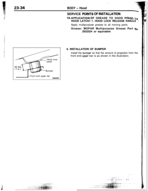
9. INSTALLATION OF SIDE PROTECT MOULDING FEN-
DER/10. SIDE PROTECT MOULDING FRONT DOOR/11. SIDE PROTECT MOULDING QUARTER
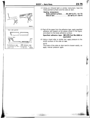
(1) Wipe off application surface of body with clean cloth
dampened with degreaser (MOPAR SUPER KLEEN or
equivalent).
NOTEAfter wiping surface, leave surface as it is to volatilize
degreaser.(2) Using an infrared light or similar instrument, heat the
body painted surface and the side protect moulding.
Heating temperature
Body painted surface..,.. 25-55OC (77-131OF)
Side protect moulding....
25-40°C (77-104OF)
* 1. Bumper absorber
2. Lower plate
3. Front bumper reinforcement
4. Front bumper
fascia
NOTE(1) Reverse the disassembly procedures")

nl lnstallatron of Rear End Trim
td19AO947
Rear bumper ass")

 Reverse the disassembly procedures to reassemble.(2)
++ : Refer to")

1. Front deck garn")
