1993 FORD MONDEO cooling
[x] Cancel search: coolingPage 35 of 279
pleated-paper type filter, it cannot be washed
or re-oiled. If it cannot be cleaned
satisfactorily with compressed air, discard
and renew it.
Warning: Wear eye protection
when using compressed air!
8Refitting is the reverse of the removal
procedure; ensure that the element and
housing are securely seated, so that unfiltered
air cannot enter the passenger compartment.
Note:If the antifreeze used is Ford’s own, or of
similar quality, the coolant need not be
renewed for the life of the vehicle. If the
vehicle’s history is unknown, if antifreeze of
lesser quality is known to be in the system, or
simply if you prefer to follow conventional
servicing intervals, the coolant should be
changed periodically (typically, every 2 years)
as described here. Refer also to the
information in Section 2 of this Chapter.
Warning: Do not allow antifreeze
to come in contact with your skin
or painted surfaces of the
vehicle. Flush contaminated areas
immediately with plenty of water. Don’t
store new coolant, or leave old coolant
lying around, where it’s accessible to
children or pets - they’re attracted by its
sweet smell. Ingestion of even a small
amount of coolant can be fatal! Wipe up
garage-floor and drip-pan spills
immediately. Keep antifreeze containers
covered, and repair cooling system leaks
as soon as they’re noticed.
Warning: Never remove the
expansion tank filler cap when
the engine is running, or has just
been switched off, as the cooling system
will be hot, and the consequent escaping
steam and scalding coolant could cause
serious injury.
Coolant draining
Warning: Wait until the engine is
cold before starting this
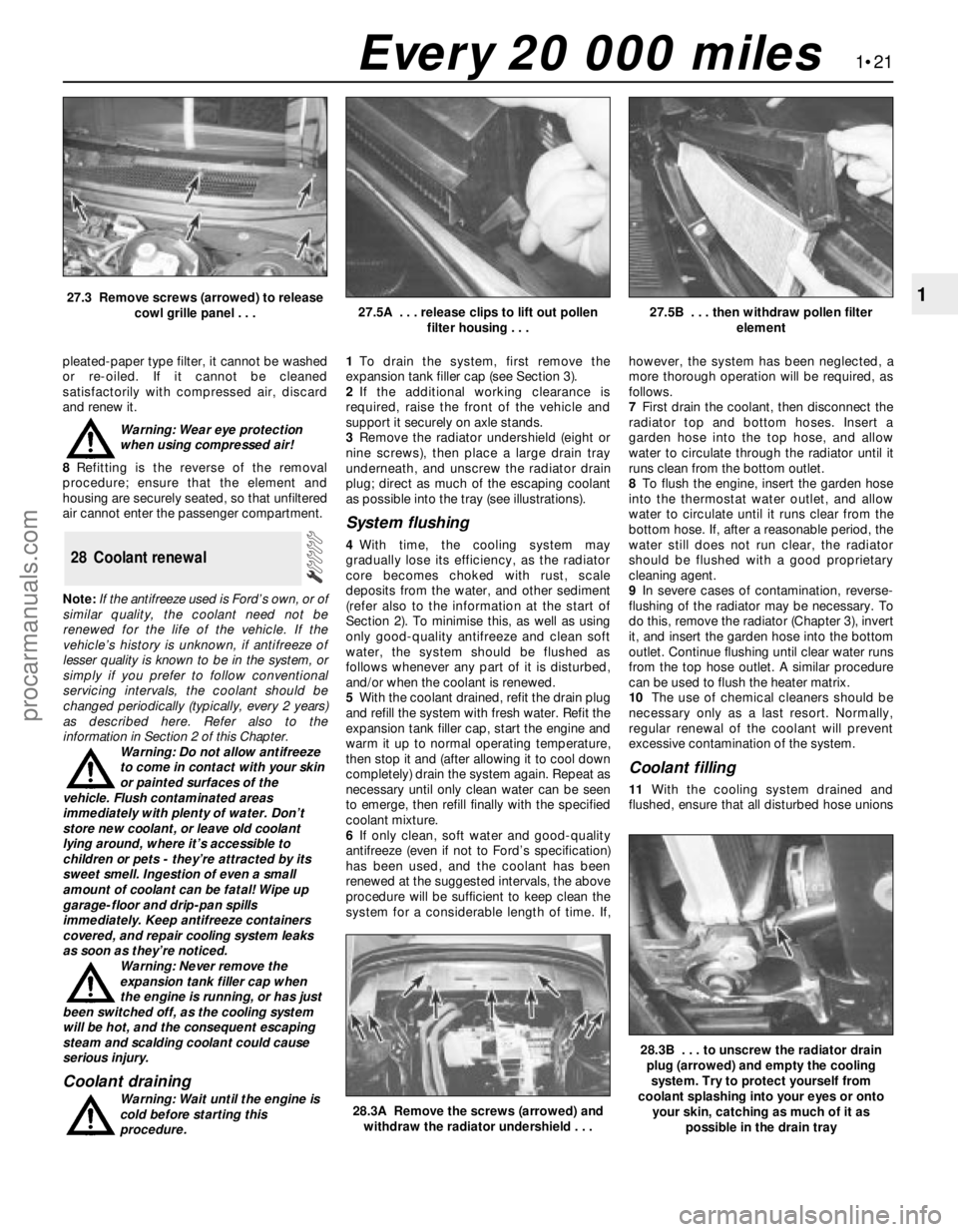
procedure.1To drain the system, first remove the
expansion tank filler cap (see Section 3).
2If the additional working clearance is
required, raise the front of the vehicle and
support it securely on axle stands.
3Remove the radiator undershield (eight or
nine screws), then place a large drain tray
underneath, and unscrew the radiator drain
plug; direct as much of the escaping coolant
as possible into the tray (see illustrations).
System flushing
4With time, the cooling system may
gradually lose its efficiency, as the radiator
core becomes choked with rust, scale
deposits from the water, and other sediment
(refer also to the information at the start of
Section 2). To minimise this, as well as using
only good-quality antifreeze and clean soft
water, the system should be flushed as
follows whenever any part of it is disturbed,
and/or when the coolant is renewed.
5With the coolant drained, refit the drain plug
and refill the system with fresh water. Refit the
expansion tank filler cap, start the engine and
warm it up to normal operating temperature,
then stop it and (after allowing it to cool down
completely) drain the system again. Repeat as
necessary until only clean water can be seen
to emerge, then refill finally with the specified
coolant mixture.
6If only clean, soft water and good-quality
antifreeze (even if not to Ford’s specification)
has been used, and the coolant has been
renewed at the suggested intervals, the above
procedure will be sufficient to keep clean the
system for a considerable length of time. If,however, the system has been neglected, a
more thorough operation will be required, as
follows.
7First drain the coolant, then disconnect the
radiator top and bottom hoses. Insert a
garden hose into the top hose, and allow
water to circulate through the radiator until it
runs clean from the bottom outlet.
8To flush the engine, insert the garden hose
into the thermostat water outlet, and allow
water to circulate until it runs clear from the
bottom hose. If, after a reasonable period, the
water still does not run clear, the radiator
should be flushed with a good proprietary
cleaning agent.
9In severe cases of contamination, reverse-
flushing of the radiator may be necessary. To
do this, remove the radiator (Chapter 3), invert
it, and insert the garden hose into the bottom
outlet. Continue flushing until clear water runs
from the top hose outlet. A similar procedure
can be used to flush the heater matrix.
10The use of chemical cleaners should be
necessary only as a last resort. Normally,
regular renewal of the coolant will prevent
excessive contamination of the system.
Coolant filling
11With the cooling system drained and
flushed, ensure that all disturbed hose unions
28 Coolant renewal
1•21
1
28.3A Remove the screws (arrowed) and
withdraw the radiator undershield . . .
28.3B . . . to unscrew the radiator drain
plug (arrowed) and empty the cooling
system. Try to protect yourself from
coolant splashing into your eyes or onto
your skin, catching as much of it as
possible in the drain tray
27.3 Remove screws (arrowed) to release
cowl grille panel . . .27.5A . . . release clips to lift out pollen
filter housing . . .27.5B . . . then withdraw pollen filter
element
Every 20 000 miles
procarmanuals.com
Page 36 of 279
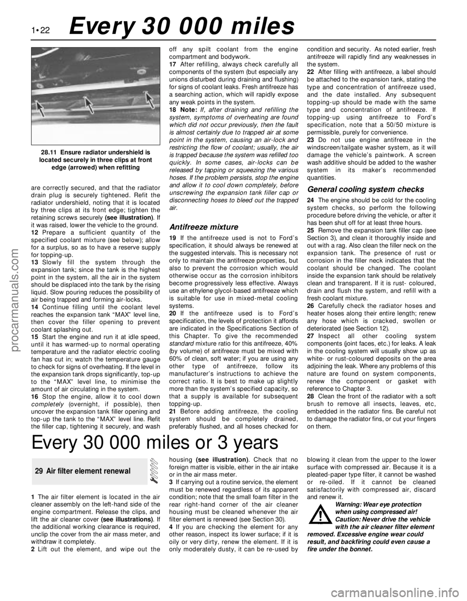
are correctly secured, and that the radiator
drain plug is securely tightened. Refit the
radiator undershield, noting that it is located
by three clips at its front edge; tighten the
retaining screws securely (see illustration). If
it was raised, lower the vehicle to the ground.
12Prepare a sufficient quantity of the
specified coolant mixture (see below); allow
for a surplus, so as to have a reserve supply
for topping-up.
13Slowly fill the system through the
expansion tank; since the tank is the highest
point in the system, all the air in the system
should be displaced into the tank by the rising
liquid. Slow pouring reduces the possibility of
air being trapped and forming air-locks.
14Continue filling until the coolant level
reaches the expansion tank “MAX” level line,
then cover the filler opening to prevent
coolant splashing out.
15Start the engine and run it at idle speed,
until it has warmed-up to normal operating
temperature and the radiator electric cooling
fan has cut in; watch the temperature gauge
to check for signs of overheating. If the level in
the expansion tank drops significantly, top-up
to the “MAX” level line, to minimise the
amount of air circulating in the system.
16Stop the engine, allow it to cool down
completely(overnight, if possible), then
uncover the expansion tank filler opening and
top-up the tank to the “MAX” level line. Refit
the filler cap, tightening it securely, and washoff any spilt coolant from the engine
compartment and bodywork.
17After refilling, always check carefully all
components of the system (but especially any
unions disturbed during draining and flushing)
for signs of coolant leaks. Fresh antifreeze has
a searching action, which will rapidly expose
any weak points in the system.
18 Note:If, after draining and refilling the
system, symptoms of overheating are found
which did not occur previously, then the fault
is almost certainly due to trapped air at some
point in the system, causing an air-lock and
restricting the flow of coolant; usually, the air
is trapped because the system was refilled too
quickly. In some cases, air-locks can be
released by tapping or squeezing the various
hoses. If the problem persists, stop the engine
and allow it to cool down completely, before
unscrewing the expansion tank filler cap or
disconnecting hoses to bleed out the trapped
air.
Antifreeze mixture
19If the antifreeze used is not to Ford’s
specification, it should always be renewed at
the suggested intervals. This is necessary not
only to maintain the antifreeze properties, but
also to prevent the corrosion which would
otherwise occur as the corrosion inhibitors
become progressively less effective. Always
use an ethylene glycol-based antifreeze which
is suitable for use in mixed-metal cooling
systems.
20If the antifreeze used is to Ford’s
specification, the levels of protection it affords
are indicated in the Specifications Section of
this Chapter. To give the recommended
standardmixture ratio for this antifreeze, 40%
(by volume) of antifreeze must be mixed with
60% of clean, soft water; if you are using any
other type of antifreeze, follow its
manufacturer’s instructions to achieve the
correct ratio. It is best to make up slightly
more than the system’s specified capacity, so
that a supply is available for subsequent
topping-up.
21Before adding antifreeze, the cooling
system should be completely drained,
preferably flushed, and all hoses checked forcondition and security. As noted earlier, fresh
antifreeze will rapidly find any weaknesses in
the system.
22After filling with antifreeze, a label should
be attached to the expansion tank, stating the
type and concentration of antifreeze used,
and the date installed. Any subsequent
topping-up should be made with the same
type and concentration of antifreeze. If
topping-up using antifreeze to Ford’s
specification, note that a 50/50 mixture is
permissible, purely for convenience.
23Do not use engine antifreeze in the
windscreen/tailgate washer system, as it will
damage the vehicle’s paintwork. A screen
wash additive should be added to the washer
system in its maker’s recommended
quantities.
General cooling system checks
24The engine should be cold for the cooling
system checks, so perform the following
procedure before driving the vehicle, or after it
has been shut off for at least three hours.
25Remove the expansion tank filler cap (see
Section 3), and clean it thoroughly inside and
out with a rag. Also clean the filler neck on the
expansion tank. The presence of rust or
corrosion in the filler neck indicates that the
coolant should be changed. The coolant
inside the expansion tank should be relatively
clean and transparent. If it is rust- coloured,
drain and flush the system, and refill with a
fresh coolant mixture.
26Carefully check the radiator hoses and
heater hoses along their entire length; renew
any hose which is cracked, swollen or
deteriorated (see Section 12).
27Inspect all other cooling system
components (joint faces, etc.) for leaks. A leak
in the cooling system will usually show up as
white- or rust-coloured deposits on the area
adjoining the leak. Where any problems of this
nature are found on system components,
renew the component or gasket with
reference to Chapter 3.
28Clean the front of the radiator with a soft
brush to remove all insects, leaves, etc,
embedded in the radiator fins. Be careful not
to damage the radiator fins, or cut your fingers
on them.
1•22
28.11 Ensure radiator undershield is
located securely in three clips at front
edge (arrowed) when refitting
Every 30 000 miles
Every 30 000 miles or 3 years
1The air filter element is located in the air
cleaner assembly on the left-hand side of the
engine compartment. Release the clips, and
lift the air cleaner cover (see illustrations). If
the additional working clearance is required,
unclip the cover from the air mass meter, and
withdraw it completely.
2Lift out the element, and wipe out thehousing (see illustration). Check that no
foreign matter is visible, either in the air intake
or in the air mass meter.
3If carrying out a routine service, the element
must be renewed regardless of its apparent
condition; note that the small foam filter in the
rear right-hand corner of the air cleaner
housing must be cleaned whenever the air
filter element is renewed (see Section 30).
4If you are checking the element for any
other reason, inspect its lower surface; if it is
oily or very dirty, renew the element. If it is
only moderately dusty, it can be re-used byblowing it clean from the upper to the lower
surface with compressed air. Because it is a
pleated-paper type filter, it cannot be washed
or re-oiled. If it cannot be cleaned
satisfactorily with compressed air, discard
and renew it.
Warning: Wear eye protection
when using compressed air!
Caution: Never drive the vehicle
with the air cleaner filter element
removed. Excessive engine wear could
result, and backfiring could even cause a
fire under the bonnet.
29 Air filter element renewal
procarmanuals.com
Page 38 of 279
To prevent the possibility of mixing up spark
plug (HT) leads, it is a good idea to try to work
on one spark plug at a time.
4If the marks on the original-equipment
spark plug (HT) leads cannot be seen, mark
the leads 1 to 4, to correspond to the cylinder
the lead serves (No 1 cylinder is at the timing
belt end of the engine). Pull the leads from the
plugs by gripping the rubber boot sealing thecylinder head cover opening, not the lead,
otherwise the lead connection may be
fractured.
5It is advisable to soak up any water in the
spark plug recesses with a rag, and to remove
any dirt from them using a clean brush,
vacuum cleaner or compressed air before
removing the plugs, to prevent any dirt or
water from dropping into the cylinders. Warning: Wear eye protection
when using compressed air!
6Unscrew the spark plugs, ensuring that the
socket is kept in alignment with each plug - if
the socket is forcibly moved to either side, the
porcelain top of the plug may be broken off. If
any undue difficulty is encountered when
unscrewing any of the spark plugs, carefully
1•24Every 30 000 miles
Specifications
Engine
Direction of crankshaft rotation . . . . . . . . . . . . . . . . . . . . . . . . . . . . . . . . Clockwise (seen from right-hand side of vehicle)
Oil filter . . . . . . . . . . . . . . . . . . . . . . . . . . . . . . . . . . . . . . . . . . . . . . . . . . Champion C148
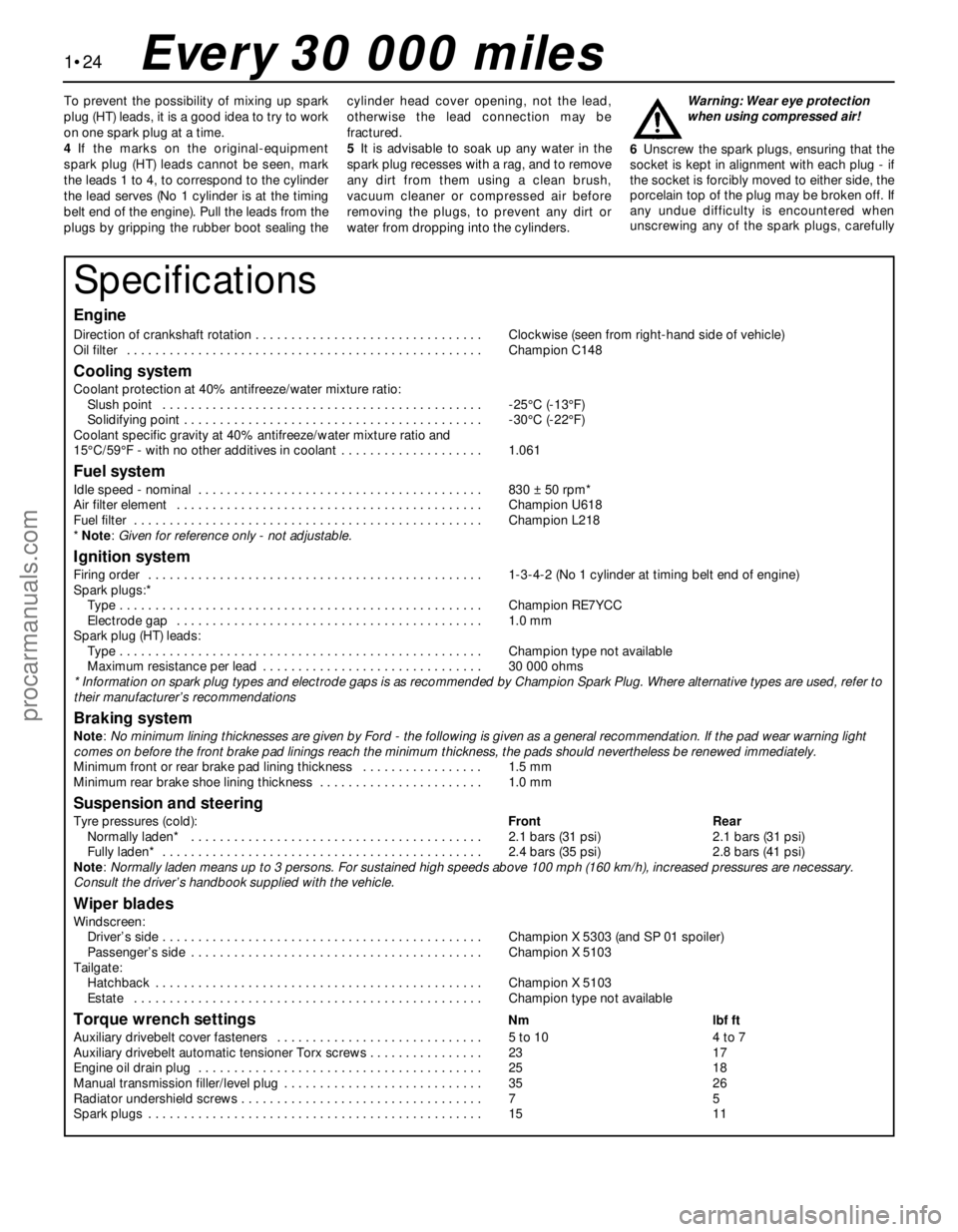
Cooling system
Coolant protection at 40% antifreeze/water mixture ratio:
Slush point . . . . . . . . . . . . . . . . . . . . . . . . . . . . . . . . . . . . . . . . . . . . . -25°C (-13°F)
Solidifying point . . . . . . . . . . . . . . . . . . . . . . . . . . . . . . . . . . . . . . . . . . -30°C (-22°F)
Coolant specific gravity at 40% antifreeze/water mixture ratio and
15°C/59°F - with no other additives in coolant . . . . . . . . . . . . . . . . . . . . 1.061
Fuel system
Idle speed - nominal . . . . . . . . . . . . . . . . . . . . . . . . . . . . . . . . . . . . . . . . 830 ± 50 rpm*
Air filter element . . . . . . . . . . . . . . . . . . . . . . . . . . . . . . . . . . . . . . . . . . . Champion U618
Fuel filter . . . . . . . . . . . . . . . . . . . . . . . . . . . . . . . . . . . . . . . . . . . . . . . . . Champion L218
* Note: Given for reference only - not adjustable.
Ignition system
Firing order . . . . . . . . . . . . . . . . . . . . . . . . . . . . . . . . . . . . . . . . . . . . . . . 1-3-4-2 (No 1 cylinder at timing belt end of engine)
Spark plugs:*
Type . . . . . . . . . . . . . . . . . . . . . . . . . . . . . . . . . . . . . . . . . . . . . . . . . . . Champion RE7YCC
Electrode gap . . . . . . . . . . . . . . . . . . . . . . . . . . . . . . . . . . . . . . . . . . . 1.0 mm
Spark plug (HT) leads:
Type . . . . . . . . . . . . . . . . . . . . . . . . . . . . . . . . . . . . . . . . . . . . . . . . . . . Champion type not available
Maximum resistance per lead . . . . . . . . . . . . . . . . . . . . . . . . . . . . . . . 30 000 ohms
* Information on spark plug types and electrode gaps is as recommended by Champion Spark Plug. Where alternative types are used, refer to
their manufacturer’s recommendations
Braking system
Note: No minimum lining thicknesses are given by Ford - the following is given as a general recommendation. If the pad wear warning light
comes on before the front brake pad linings reach the minimum thickness, the pads should nevertheless be renewed immediately.
Minimum front or rear brake pad lining thickness . . . . . . . . . . . . . . . . . 1.5 mm
Minimum rear brake shoe lining thickness . . . . . . . . . . . . . . . . . . . . . . . 1.0 mm
Suspension and steering
Tyre pressures (cold):Front Rear
Normally laden* . . . . . . . . . . . . . . . . . . . . . . . . . . . . . . . . . . . . . . . . . 2.1 bars (31 psi) 2.1 bars (31 psi)
Fully laden* . . . . . . . . . . . . . . . . . . . . . . . . . . . . . . . . . . . . . . . . . . . . . 2.4 bars (35 psi) 2.8 bars (41 psi)
Note: Normally laden means up to 3 persons. For sustained high speeds above 100 mph (160 km/h), increased pressures are necessary.
Consult the driver’s handbook supplied with the vehicle.
Wiper blades
Windscreen:
Driver’s side . . . . . . . . . . . . . . . . . . . . . . . . . . . . . . . . . . . . . . . . . . . . . Champion X 5303 (and SP 01 spoiler)
Passenger’s side . . . . . . . . . . . . . . . . . . . . . . . . . . . . . . . . . . . . . . . . . Champion X 5103
Tailgate:
Hatchback . . . . . . . . . . . . . . . . . . . . . . . . . . . . . . . . . . . . . . . . . . . . . . Champion X 5103
Estate . . . . . . . . . . . . . . . . . . . . . . . . . . . . . . . . . . . . . . . . . . . . . . . . . Champion type not available
Torque wrench settingsNm lbf ft
Auxiliary drivebelt cover fasteners . . . . . . . . . . . . . . . . . . . . . . . . . . . . . 5 to 10 4 to 7
Auxiliary drivebelt automatic tensioner Torx screws . . . . . . . . . . . . . . . . 23 17
Engine oil drain plug . . . . . . . . . . . . . . . . . . . . . . . . . . . . . . . . . . . . . . . . 25 18
Manual transmission filler/level plug . . . . . . . . . . . . . . . . . . . . . . . . . . . . 35 26
Radiator undershield screws . . . . . . . . . . . . . . . . . . . . . . . . . . . . . . . . . . 7 5
Spark plugs . . . . . . . . . . . . . . . . . . . . . . . . . . . . . . . . . . . . . . . . . . . . . . . 15 11
procarmanuals.com
Page 43 of 279
Torque wrench settings (continued)Nm lbf ft
Engine/automatic transmission rear mounting:
Mounting bracket-to-transmission . . . . . . . . . . . . . . . . . . . . . . . . . . . 48 to 49 35 to 36
Mounting-to-subframe bolts - stage 1 . . . . . . . . . . . . . . . . . . . . . . . . 10 7
Mounting-to-subframe bolts - stage 2 . . . . . . . . . . . . . . . . . . . . . . . . 48 35
Mounting centre bolt . . . . . . . . . . . . . . . . . . . . . . . . . . . . . . . . . . . . . . 120 89
Engine/transmission left-hand mounting:
Bracket-to-transmission nuts . . . . . . . . . . . . . . . . . . . . . . . . . . . . . . . 83 61
Mounting centre bolt . . . . . . . . . . . . . . . . . . . . . . . . . . . . . . . . . . . . . . Not available
Mounting-to-body bolts . . . . . . . . . . . . . . . . . . . . . . . . . . . . . . . . . . . Not available
Engine/transmission right-hand mounting:
Bracket-to-engine and mounting nuts . . . . . . . . . . . . . . . . . . . . . . . . 83 to 90 61 to 66
Mounting-to-body bolts . . . . . . . . . . . . . . . . . . . . . . . . . . . . . . . . . . . 84 62
Note:Refer to Part B of this Chapter for remaining torque wrench settings.
In-car engine repair procedures 2A•3
2A
How to use this Chapter
This Part of Chapter 2 is devoted to repair
procedures possible while the engine is still
installed in the vehicle, and includes only the
Specifications relevant to those procedures.
Since these procedures are based on the
assumption that the engine is installed in the
vehicle, if the engine has been removed from
the vehicle and mounted on a stand, some of
the preliminary dismantling steps outlined will
not apply.
Information concerning engine/transmission
removal and refitting, and engine overhaul, can
be found in Part B of this Chapter, which also
includes the Specifications relevant to those
procedures.
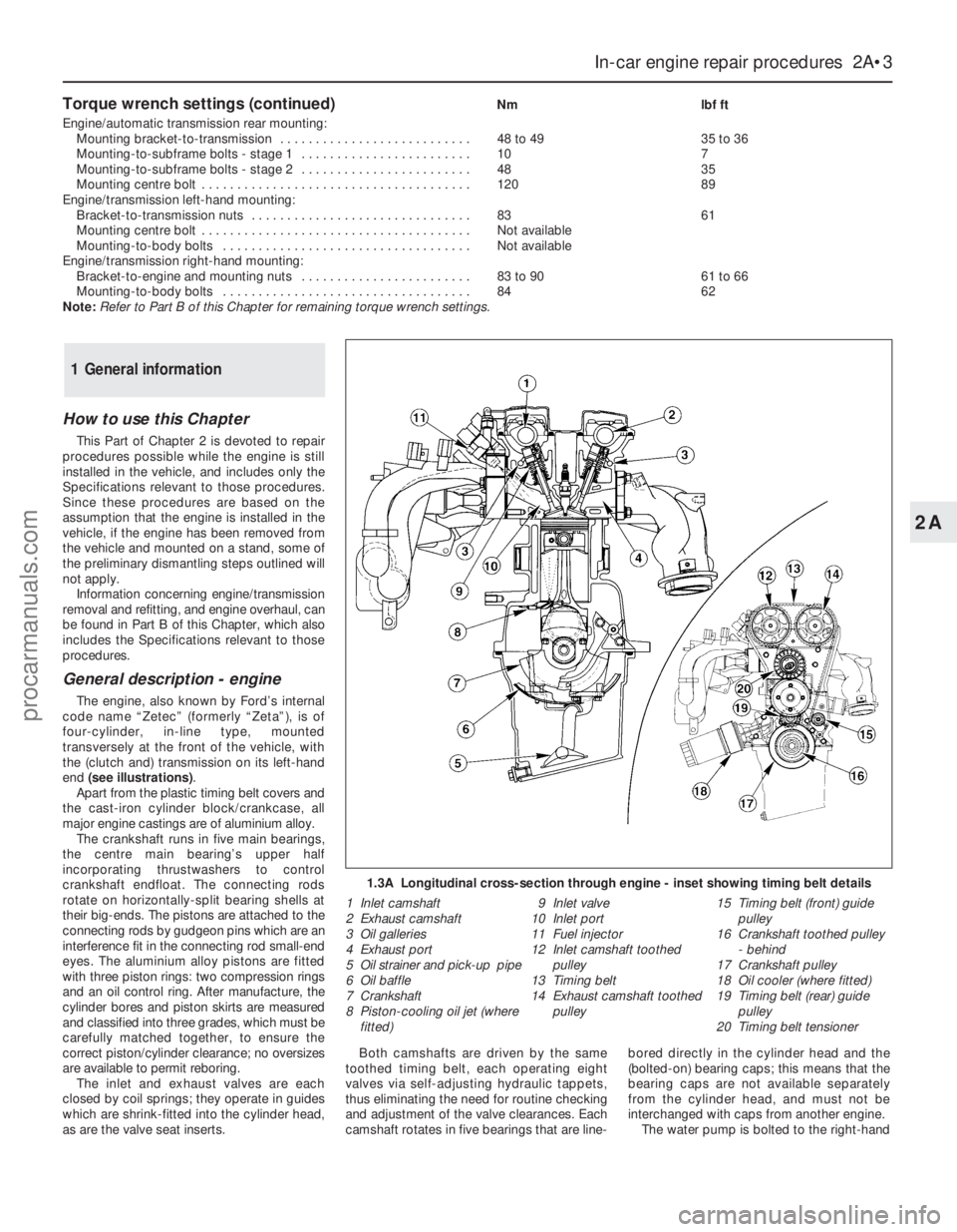
General description - engine
The engine, also known by Ford’s internal
code name “Zetec” (formerly “Zeta”), is of
four-cylinder, in-line type, mounted
transversely at the front of the vehicle, with
the (clutch and) transmission on its left-hand
end (see illustrations).
Apart from the plastic timing belt covers and
the cast-iron cylinder block/crankcase, all
major engine castings are of aluminium alloy.
The crankshaft runs in five main bearings,
the centre main bearing’s upper half
incorporating thrustwashers to control
crankshaft endfloat. The connecting rods
rotate on horizontally-split bearing shells at
their big-ends. The pistons are attached to the
connecting rods by gudgeon pins which are an
interference fit in the connecting rod small-end
eyes. The aluminium alloy pistons are fitted
with three piston rings: two compression rings
and an oil control ring. After manufacture, the
cylinder bores and piston skirts are measured
and classified into three grades, which must be
carefully matched together, to ensure the
correct piston/cylinder clearance; no oversizes
are available to permit reboring.
The inlet and exhaust valves are each
closed by coil springs; they operate in guides
which are shrink-fitted into the cylinder head,
as are the valve seat inserts.Both camshafts are driven by the same
toothed timing belt, each operating eight
valves via self-adjusting hydraulic tappets,
thus eliminating the need for routine checking
and adjustment of the valve clearances. Each
camshaft rotates in five bearings that are line-bored directly in the cylinder head and the
(bolted-on) bearing caps; this means that the
bearing caps are not available separately
from the cylinder head, and must not be
interchanged with caps from another engine.
The water pump is bolted to the right-hand
1 General information
1.3A Longitudinal cross-section through engine - inset showing timing belt details
1 Inlet camshaft
2 Exhaust camshaft
3 Oil galleries
4 Exhaust port
5 Oil strainer and pick-up pipe
6 Oil baffle
7 Crankshaft
8 Piston-cooling oil jet (where
fitted)9 Inlet valve
10 Inlet port
11 Fuel injector
12 Inlet camshaft toothed
pulley
13 Timing belt
14 Exhaust camshaft toothed
pulley15 Timing belt (front) guide
pulley
16 Crankshaft toothed pulley
- behind
17 Crankshaft pulley
18 Oil cooler (where fitted)
19 Timing belt (rear) guide
pulley
20 Timing belt tensioner
procarmanuals.com
Page 44 of 279
end of the cylinder block, inboard of the
timing belt, and is driven with the power
steering pump and alternator by a flat
“polyvee”-type auxiliary drivebelt from the
crankshaft pulley.
When working on this engine, note that
Torx-type (both male and female heads) and
hexagon socket (Allen head) fasteners are
widely used; a good selection of bits, with the
necessary adaptors, will be required, so that
these can be unscrewed without damage
and, on reassembly, tightened to the torque
wrench settings specified.
General description - lubrication
system
Lubrication is by means of an eccentric-
rotor trochoidal pump, which is mounted on
the crankshaft right-hand end, and draws oil
through a strainer located in the sump. The
pump forces oil through an externally-
mounted full-flow cartridge-type filter - on
some versions of the engine, an oil cooler is
fitted to the oil filter mounting, so that clean
oil entering the engine’s galleries is cooled by
the main engine cooling system. From the
filter, the oil is pumped into a main gallery in
the cylinder block/crankcase, from where it is
distributed to the crankshaft (main bearings)
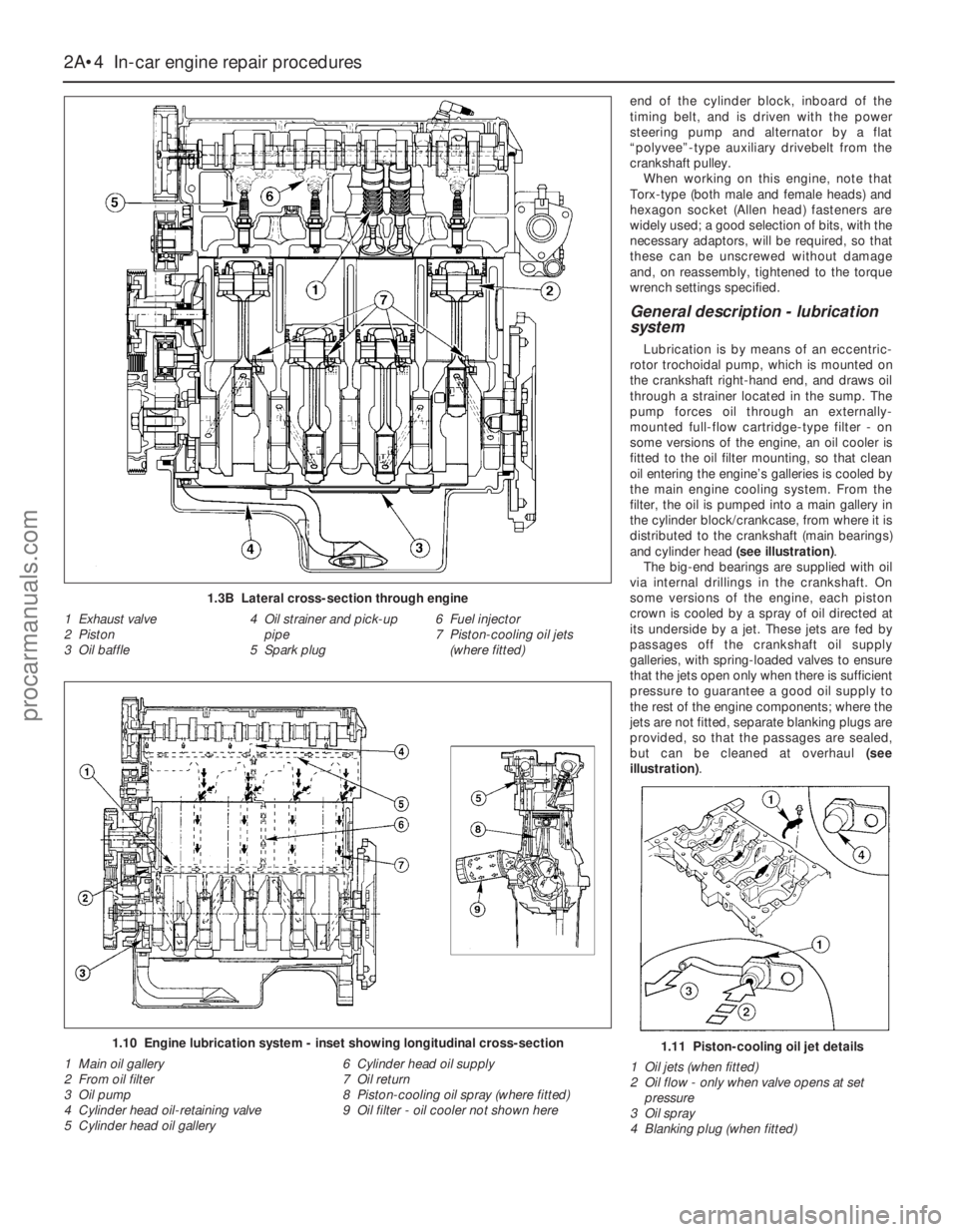
and cylinder head (see illustration).
The big-end bearings are supplied with oil
via internal drillings in the crankshaft. On
some versions of the engine, each piston
crown is cooled by a spray of oil directed at
its underside by a jet. These jets are fed by
passages off the crankshaft oil supply
galleries, with spring-loaded valves to ensure
that the jets open only when there is sufficient
pressure to guarantee a good oil supply to
the rest of the engine components; where the
jets are not fitted, separate blanking plugs are
provided, so that the passages are sealed,
but can be cleaned at overhaul (see
illustration).
2A•4 In-car engine repair procedures
1.3B Lateral cross-section through engine
1 Exhaust valve
2 Piston
3 Oil baffle4 Oil strainer and pick-up
pipe
5 Spark plug6 Fuel injector
7 Piston-cooling oil jets
(where fitted)
1.10 Engine lubrication system - inset showing longitudinal cross-section
1 Main oil gallery
2 From oil filter
3 Oil pump
4 Cylinder head oil-retaining valve
5 Cylinder head oil gallery6 Cylinder head oil supply
7 Oil return
8 Piston-cooling oil spray (where fitted)
9 Oil filter - oil cooler not shown here1.11 Piston-cooling oil jet details
1 Oil jets (when fitted)
2 Oil flow - only when valve opens at set
pressure
3 Oil spray
4 Blanking plug (when fitted)
procarmanuals.com
Page 48 of 279
16Unscrew the bolts and nuts securing the
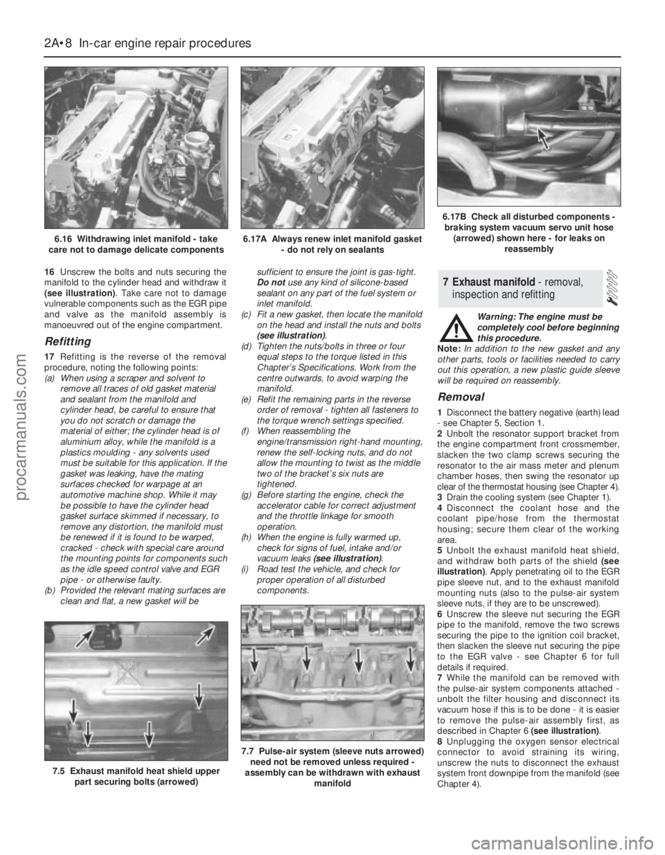
manifold to the cylinder head and withdraw it
(see illustration). Take care not to damage
vulnerable components such as the EGR pipe
and valve as the manifold assembly is
manoeuvred out of the engine compartment.
Refitting
17Refitting is the reverse of the removal
procedure, noting the following points:
(a) When using a scraper and solvent to
remove all traces of old gasket material
and sealant from the manifold and
cylinder head, be careful to ensure that
you do not scratch or damage the
material of either; the cylinder head is of
aluminium alloy, while the manifold is a
plastics moulding - any solvents used
must be suitable for this application. If the
gasket was leaking, have the mating
surfaces checked for warpage at an
automotive machine shop. While it may
be possible to have the cylinder head
gasket surface skimmed if necessary, to
remove any distortion, the manifold must
be renewed if it is found to be warped,
cracked - check with special care around
the mounting points for components such
as the idle speed control valve and EGR
pipe - or otherwise faulty.
(b) Provided the relevant mating surfaces are
clean and flat, a new gasket will besufficient to ensure the joint is gas-tight.
Do notuse any kind of silicone-based
sealant on any part of the fuel system or
inlet manifold.
(c) Fit a new gasket, then locate the manifold
on the head and install the nuts and bolts
(see illustration).
(d) Tighten the nuts/bolts in three or four
equal steps to the torque listed in this
Chapter’s Specifications. Work from the
centre outwards, to avoid warping the
manifold.
(e) Refit the remaining parts in the reverse
order of removal - tighten all fasteners to
the torque wrench settings specified.
(f) When reassembling the
engine/transmission right-hand mounting,
renew the self-locking nuts, and do not
allow the mounting to twist as the middle
two of the bracket’s six nuts are
tightened.
(g) Before starting the engine, check the
accelerator cable for correct adjustment
and the throttle linkage for smooth
operation.
(h) When the engine is fully warmed up,
check for signs of fuel, intake and/or
vacuum leaks (see illustration).
(i) Road test the vehicle, and check for
proper operation of all disturbed
components.Warning: The engine must be
completely cool before beginning
this procedure.
Note:In addition to the new gasket and any
other parts, tools or facilities needed to carry
out this operation, a new plastic guide sleeve
will be required on reassembly.
Removal
1Disconnect the battery negative (earth) lead
- see Chapter 5, Section 1.
2Unbolt the resonator support bracket from
the engine compartment front crossmember,
slacken the two clamp screws securing the
resonator to the air mass meter and plenum
chamber hoses, then swing the resonator up
clear of the thermostat housing (see Chapter 4).
3Drain the cooling system (see Chapter 1).
4Disconnect the coolant hose and the
coolant pipe/hose from the thermostat
housing; secure them clear of the working
area.
5Unbolt the exhaust manifold heat shield,
and withdraw both parts of the shield (see
illustration). Apply penetrating oil to the EGR
pipe sleeve nut, and to the exhaust manifold
mounting nuts (also to the pulse-air system
sleeve nuts, if they are to be unscrewed).
6Unscrew the sleeve nut securing the EGR
pipe to the manifold, remove the two screws
securing the pipe to the ignition coil bracket,
then slacken the sleeve nut securing the pipe
to the EGR valve - see Chapter 6 for full
details if required.
7While the manifold can be removed with
the pulse-air system components attached -
unbolt the filter housing and disconnect its
vacuum hose if this is to be done - it is easier
to remove the pulse-air assembly first, as
described in Chapter 6 (see illustration).
8Unplugging the oxygen sensor electrical
connector to avoid straining its wiring,
unscrew the nuts to disconnect the exhaust
system front downpipe from the manifold (see
Chapter 4).
7 Exhaust manifold - removal,
inspection and refitting
2A•8 In-car engine repair procedures
6.16 Withdrawing inlet manifold - take
care not to damage delicate components6.17A Always renew inlet manifold gasket
- do not rely on sealants
6.17B Check all disturbed components -
braking system vacuum servo unit hose
(arrowed) shown here - for leaks on
reassembly
7.5 Exhaust manifold heat shield upper
part securing bolts (arrowed)
7.7 Pulse-air system (sleeve nuts arrowed)
need not be removed unless required -
assembly can be withdrawn with exhaust
manifold
procarmanuals.com
Page 49 of 279
9Remove the nuts and detach the manifold
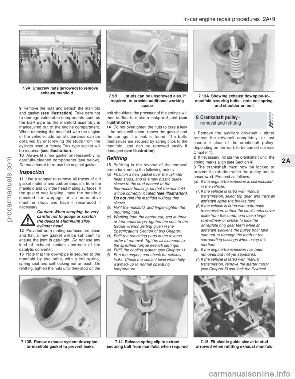
and gasket (see illustration). Take care not
to damage vulnerable components such as
the EGR pipe as the manifold assembly is
manoeuvred out of the engine compartment.
When removing the manifold with the engine
in the vehicle, additional clearance can be
obtained by unscrewing the studs from the
cylinder head; a female Torx-type socket will
be required (see illustration).
10Always fit a new gasket on reassembly, to
carefully-cleaned components (see below).
Do notattempt to re-use the original gasket.
Inspection
11Use a scraper to remove all traces of old
gasket material and carbon deposits from the
manifold and cylinder head mating surfaces. If
the gasket was leaking, have the manifold
checked for warpage at an automotive
machine shop, and have it resurfaced if
necessary.
Caution: When scraping, be very
careful not to gouge or scratch
the delicate aluminium alloy
cylinder head.
12Provided both mating surfaces are clean
and flat, a new gasket will be sufficient to
ensure the joint is gas-tight. Do notuse any
kind of exhaust sealant upstream of the
catalytic converter.
13Note that the downpipe is secured to the
manifold by two bolts, with a coil spring,
spring seat and self-locking nut on each. On
refitting, tighten the nuts until they stop on thebolt shoulders; the pressure of the springs will
then suffice to make a leakproof joint (see
illustrations).
14Do not overtighten the nuts to cure a leak
- the bolts will shear; renew the gasket and
the springs if a leak is found. The bolts
themselves are secured by spring clips to the
manifold, and can be renewed easily if
damaged (see illustration).
Refitting
15Refitting is the reverse of the removal
procedure, noting the following points:
(a) Position a new gasket over the cylinder
head studs, and fit a new plastic guide
sleeve to the stud nearest to the
thermostat housing, so that the manifold
will be correctly located (see illustration).
Do notrefit the manifold without this
sleeve.
(b) Refit the manifold, and finger-tighten the
mounting nuts.
(c) Working from the centre out, and in three
or four equal steps, tighten the nuts to the
torque wrench setting given in the
Specifications Section of this Chapter.
(d) Refit the remaining parts in the reverse
order of removal. Tighten all fasteners to
the specified torque wrench settings.
(e) Refill the cooling system (see Chapter 1).
(f) Run the engine, and check for exhaust
leaks. Check the coolant level when fully
warmed-up to normal operating
temperature.1Remove the auxiliary drivebelt - either
remove the drivebelt completely, or just
secure it clear of the crankshaft pulley,
depending on the work to be carried out (see
Chapter 1).
2If necessary, rotate the crankshaft until the
timing marks align (see Section 4).
3The crankshaft must now be locked to
prevent its rotation while the pulley bolt is
unscrewed. Proceed as follows:
(a) If the engine/transmission is still installed
in the vehicle:
(1) If the vehicle is fitted with manual
transmission, select top gear, and have an
assistant apply the brakes hard.
(2) If the vehicle is fitted with automatic
transmission, unbolt the small metal cover
plate from the sump, and use a large
screwdriver or similar to lock the
driveplate ring gear teeth while an
assistant slackens the pulley bolt; take
care not to damage the teeth or the
surrounding castings when using this
method.
(b) If the engine/transmission has been
removed but not yet separated:
(1) If the vehicle is fitted with manual
transmission, remove the starter motor
(see Chapter 5) and lock the flywheel
8 Crankshaft pulley -
removal and refitting
In-car engine repair procedures 2A•9
2A
7.13B Renew exhaust system downpipe-
to-manifold gasket to prevent leaks7.14 Release spring clip to extract
securing bolt from manifold, when required7.15 Fit plastic guide sleeve to stud
arrowed when refitting exhaust manifold
7.9A Unscrew nuts (arrowed) to remove
exhaust manifold . . .
7.9B . . . studs can be unscrewed also, if
required, to provide additional working
space7.13A Showing exhaust downpipe-to-
manifold securing bolts - note coil spring,
and shoulder on bolt
procarmanuals.com
Page 57 of 279
23If using Ford’s recommended procedure,
fit new oil seals to the camshafts as
described in paragraph 5 of Section 12.
24Using the marks and notes made on
dismantling to ensure that each is refitted to
its original camshaft, refit the toothed pulleys
to the camshafts, tightening the retaining
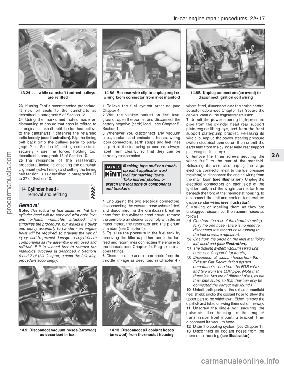
bolts loosely (see illustration). Slip the timing
belt back onto the pulleys (refer to para-
graph 21 of Section 10) and tighten the bolts
securely - use the forked holding tool
described in paragraph 18 of Section 10.
25The remainder of the reassembly
procedure, including checking the camshaft
alignment (valve timing) and setting the timing
belt tension, is as described in paragraphs 17
to 27 of Section 10.
Removal
Note:The following text assumes that the
cylinder head will be removed with both inlet
and exhaust manifolds attached; this
simplifies the procedure, but makes it a bulky
and heavy assembly to handle - an engine
hoist will be required, to prevent the risk of
injury, and to prevent damage to any delicate
components as the assembly is removed and
refitted. If it is wished first to remove the
manifolds, proceed as described in Sections
6 and 7 of this Chapter; amend the following
procedure accordingly.1Relieve the fuel system pressure (see
Chapter 4).
2With the vehicle parked on firm level
ground, open the bonnet and disconnect the
battery negative (earth) lead - see Chapter 5,
Section 1.
3Whenever you disconnect any vacuum
lines, coolant and emissions hoses, wiring
loom connectors, earth straps and fuel lines
as part of the following procedure, always
label them clearly, so that they can be
correctly reassembled.
4Unplugging the two electrical connectors,
disconnecting the vacuum hose (where fitted)
and disconnecting the crankcase breather
hose from the cylinder head cover, remove
the complete air cleaner assembly with the air
mass meter, the resonator and the plenum
chamber (see Chapter 4).
5Equalise the pressure in the fuel tank by
removing the filler cap, then undo the fuel
feed and return lines connecting the engine to
the chassis (see Chapter 4). Plug or cap all
open fittings.
6Disconnect the accelerator cable from the
throttle linkage as described in Chapter 4 -where fitted, disconnect also the cruise control
actuator cable (see Chapter 12). Secure the
cable(s) clear of the engine/transmission.
7Unbolt the power steering high-pressure
pipe from the cylinder head rear support
plate/engine lifting eye, and from the front
support plate/pump bracket. Releasing its
wire clip, unplug the power steering pressure
switch electrical connector, then unbolt the
earth lead from the cylinder head rear support
plate/engine lifting eye.
8Remove the three screws securing the
wiring “rail” to the rear of the manifold.
Releasing its wire clip, unplug the large
electrical connector (next to the fuel pressure
regulator) to disconnect the engine wiring from
the main loom (see illustration). Unplug the
electrical connectors on each side of the
ignition coil, and the single connector from
beneath the front of the thermostat housing, to
disconnect the coil and coolant temperature
gauge sender wiring (see illustration).
9Marking or labelling them as they are
unplugged, disconnect the vacuum hoses as
follows:
(a) One from the rear of the throttle housing
(only the one hose - there is no need to
disconnect the second hose running to
the fuel pressure regulator).
(b) One from the union on the inlet manifold’s
left-hand end (see illustration).
(c) The braking system vacuum servo unit
hose (see Chapter 9 for details).
(d) Disconnect all vacuum hoses from the
Exhaust Gas Recirculation system
components - one from the EGR valve
and two from the EGR pipe. (Note that
these last two are of different sizes, as are
their pipe stubs, so that they can only be
connected the correct way round.)
10Unbolt both parts of the exhaust manifold
heat shield; unclip the coolant hose to allow the
upper part to be withdrawn. Either remove the
dipstick and tube, or swing them out of the way.
11Unscrew the single bolt securing the
pulse-air filter housing to the engine/
transmission front mounting bracket, then
disconnect its vacuum hose.
12Drain the cooling system (see Chapter 1).
13Disconnect all coolant hoses from the
thermostat housing (see illustration).
14 Cylinder head -
removal and refitting
In-car engine repair procedures 2A•17
2A
14.9 Disconnect vacuum hoses (arrowed)
as described in text14.13 Disconnect all coolant hoses
(arrowed) from thermostat housing
13.24 . . . while camshaft toothed pulleys
are refitted14.8A Release wire clip to unplug engine
wiring loom connector from inlet manifold14.8B Unplug connectors (arrowed) to
disconnect ignition coil wiring
Masking tape and/or a touch-
up paint applicator work
well for marking items.
Take instant photos, or
sketch the locations of components
and brackets.
procarmanuals.com