1993 FORD MONDEO cooling
[x] Cancel search: coolingPage 93 of 279
sender’s electrical connector, and use a
jumper wire to connect the white/red wire to a
clean earth point (bare metal) on the engine.
Switch on the ignition without starting the
engine. If the gauge now indicates Hot, renew
the sender.
5If the gauge still does not work, the circuit
may be open, or the gauge may be faulty. See
Chapter 12 for additional information.
Removal
6Unbolt the resonator support bracket from
the engine compartment front crossmember.
Slacken the two clamp screws securing the
resonator to the air mass meter and plenum
chamber hoses, then swing the resonator up
clear of the thermostat housing (see Chap-
ter 4).
7Drain the cooling system (see Chapter 1).
8Disconnect the expansion tank coolant
hose and the radiator top hose from the
thermostat housing’s water outlet, then
disconnect the metal coolant pipe/hose from
the thermostat.
9Unplug the electrical connector from the
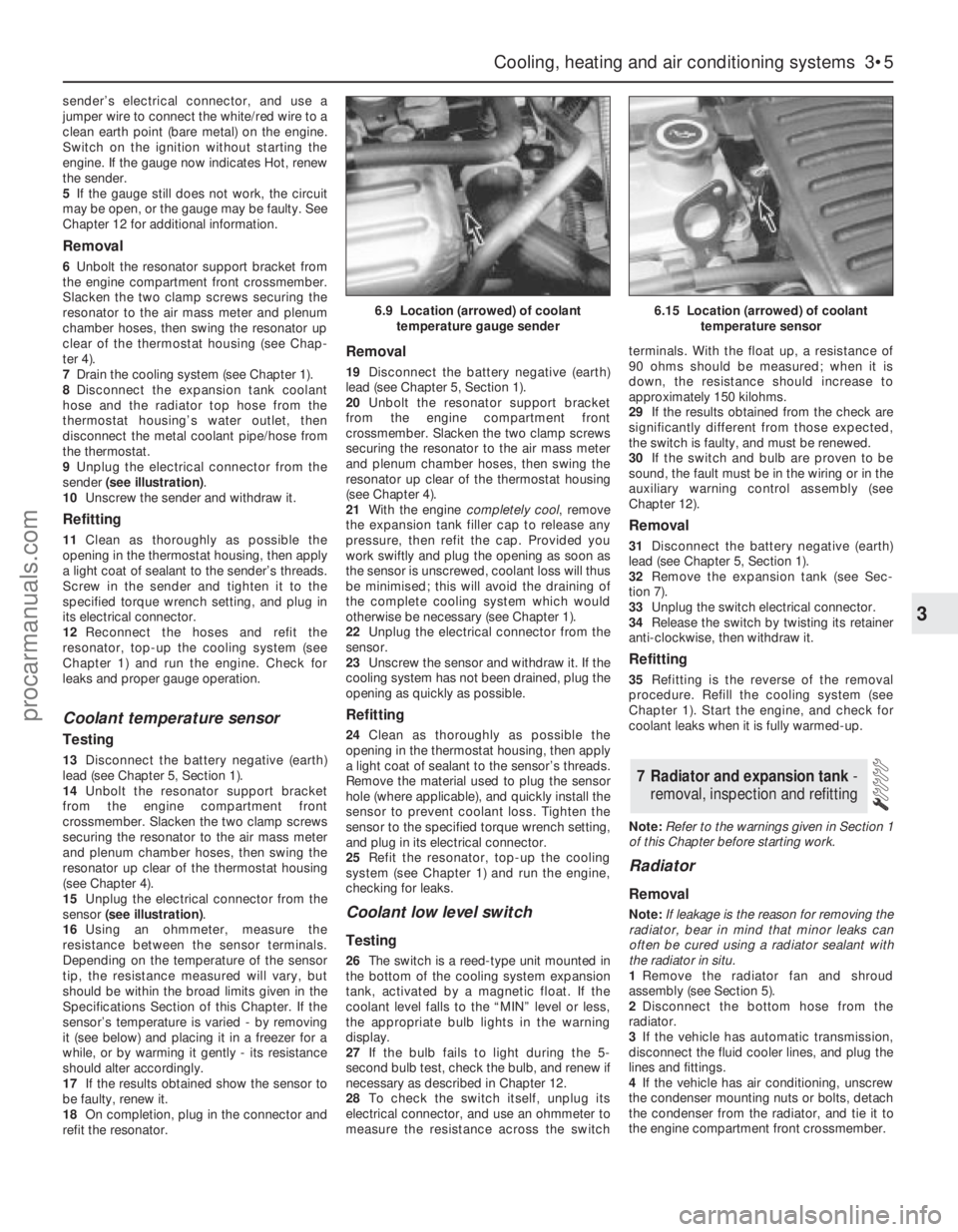
sender (see illustration).
10Unscrew the sender and withdraw it.
Refitting
11Clean as thoroughly as possible the
opening in the thermostat housing, then apply
a light coat of sealant to the sender’s threads.
Screw in the sender and tighten it to the
specified torque wrench setting, and plug in
its electrical connector.
12Reconnect the hoses and refit the
resonator, top-up the cooling system (see
Chapter 1) and run the engine. Check for
leaks and proper gauge operation.
Coolant temperature sensor
Testing
13Disconnect the battery negative (earth)
lead (see Chapter 5, Section 1).
14Unbolt the resonator support bracket
from the engine compartment front
crossmember. Slacken the two clamp screws
securing the resonator to the air mass meter
and plenum chamber hoses, then swing the
resonator up clear of the thermostat housing
(see Chapter 4).
15Unplug the electrical connector from the
sensor (see illustration).
16Using an ohmmeter, measure the
resistance between the sensor terminals.
Depending on the temperature of the sensor
tip, the resistance measured will vary, but
should be within the broad limits given in the
Specifications Section of this Chapter. If the
sensor’s temperature is varied - by removing
it (see below) and placing it in a freezer for a
while, or by warming it gently - its resistance
should alter accordingly.
17If the results obtained show the sensor to
be faulty, renew it.
18On completion, plug in the connector and
refit the resonator.
Removal
19Disconnect the battery negative (earth)
lead (see Chapter 5, Section 1).
20Unbolt the resonator support bracket
from the engine compartment front
crossmember. Slacken the two clamp screws
securing the resonator to the air mass meter
and plenum chamber hoses, then swing the
resonator up clear of the thermostat housing
(see Chapter 4).
21With the engine completely cool, remove
the expansion tank filler cap to release any
pressure, then refit the cap. Provided you
work swiftly and plug the opening as soon as
the sensor is unscrewed, coolant loss will thus
be minimised; this will avoid the draining of
the complete cooling system which would
otherwise be necessary (see Chapter 1).
22Unplug the electrical connector from the
sensor.
23Unscrew the sensor and withdraw it. If the
cooling system has not been drained, plug the
opening as quickly as possible.
Refitting
24Clean as thoroughly as possible the
opening in the thermostat housing, then apply
a light coat of sealant to the sensor’s threads.
Remove the material used to plug the sensor
hole (where applicable), and quickly install the
sensor to prevent coolant loss. Tighten the
sensor to the specified torque wrench setting,
and plug in its electrical connector.
25Refit the resonator, top-up the cooling
system (see Chapter 1) and run the engine,
checking for leaks.
Coolant low level switch
Testing
26The switch is a reed-type unit mounted in
the bottom of the cooling system expansion
tank, activated by a magnetic float. If the
coolant level falls to the “MIN” level or less,
the appropriate bulb lights in the warning
display.
27If the bulb fails to light during the 5-
second bulb test, check the bulb, and renew if
necessary as described in Chapter 12.
28To check the switch itself, unplug its
electrical connector, and use an ohmmeter to
measure the resistance across the switchterminals. With the float up, a resistance of
90 ohms should be measured; when it is
down, the resistance should increase to
approximately 150 kilohms.
29If the results obtained from the check are
significantly different from those expected,
the switch is faulty, and must be renewed.
30If the switch and bulb are proven to be
sound, the fault must be in the wiring or in the
auxiliary warning control assembly (see
Chapter 12).
Removal
31Disconnect the battery negative (earth)
lead (see Chapter 5, Section 1).
32Remove the expansion tank (see Sec-
tion 7).
33Unplug the switch electrical connector.
34Release the switch by twisting its retainer
anti-clockwise, then withdraw it.
Refitting
35Refitting is the reverse of the removal
procedure. Refill the cooling system (see
Chapter 1). Start the engine, and check for
coolant leaks when it is fully warmed-up.
Note:Refer to the warnings given in Section 1
of this Chapter before starting work.
Radiator
Removal
Note:If leakage is the reason for removing the
radiator, bear in mind that minor leaks can
often be cured using a radiator sealant with
the radiator in situ.
1Remove the radiator fan and shroud
assembly (see Section 5).
2Disconnect the bottom hose from the
radiator.
3If the vehicle has automatic transmission,
disconnect the fluid cooler lines, and plug the
lines and fittings.
4If the vehicle has air conditioning, unscrew
the condenser mounting nuts or bolts, detach
the condenser from the radiator, and tie it to
the engine compartment front crossmember.
7 Radiator and expansion tank -
removal, inspection and refitting
Cooling, heating and air conditioning systems 3•5
3
6.9 Location (arrowed) of coolant
temperature gauge sender6.15 Location (arrowed) of coolant
temperature sensor
procarmanuals.com
Page 94 of 279
Warning: Do not disconnect any
of the refrigerant hoses.
5Unbolt the radiator mounting brackets from
the subframe; note that they are handed, and
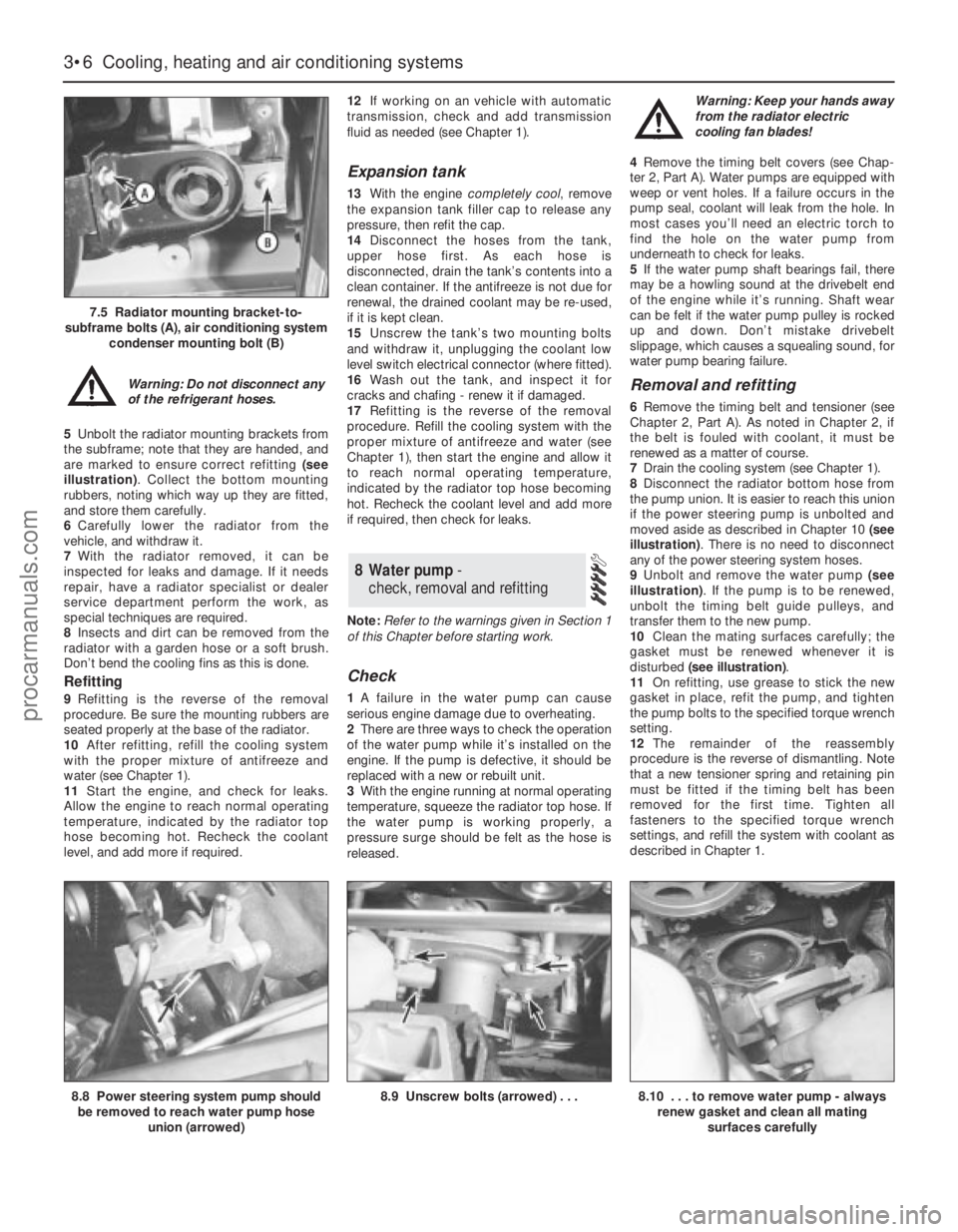
are marked to ensure correct refitting (see
illustration). Collect the bottom mounting
rubbers, noting which way up they are fitted,
and store them carefully.
6Carefully lower the radiator from the
vehicle, and withdraw it.
7With the radiator removed, it can be
inspected for leaks and damage. If it needs
repair, have a radiator specialist or dealer
service department perform the work, as
special techniques are required.
8Insects and dirt can be removed from the
radiator with a garden hose or a soft brush.
Don’t bend the cooling fins as this is done.
Refitting
9Refitting is the reverse of the removal
procedure. Be sure the mounting rubbers are
seated properly at the base of the radiator.
10After refitting, refill the cooling system
with the proper mixture of antifreeze and
water (see Chapter 1).
11Start the engine, and check for leaks.
Allow the engine to reach normal operating
temperature, indicated by the radiator top
hose becoming hot. Recheck the coolant
level, and add more if required.12If working on an vehicle with automatic
transmission, check and add transmission
fluid as needed (see Chapter 1).
Expansion tank
13With the engine completely cool, remove
the expansion tank filler cap to release any
pressure, then refit the cap.
14Disconnect the hoses from the tank,
upper hose first. As each hose is
disconnected, drain the tank’s contents into a
clean container. If the antifreeze is not due for
renewal, the drained coolant may be re-used,
if it is kept clean.
15Unscrew the tank’s two mounting bolts
and withdraw it, unplugging the coolant low
level switch electrical connector (where fitted).
16Wash out the tank, and inspect it for
cracks and chafing - renew it if damaged.
17Refitting is the reverse of the removal
procedure. Refill the cooling system with the
proper mixture of antifreeze and water (see
Chapter 1), then start the engine and allow it
to reach normal operating temperature,
indicated by the radiator top hose becoming
hot. Recheck the coolant level and add more
if required, then check for leaks.
Note:Refer to the warnings given in Section 1
of this Chapter before starting work.
Check
1A failure in the water pump can cause
serious engine damage due to overheating.
2There are three ways to check the operation
of the water pump while it’s installed on the
engine. If the pump is defective, it should be
replaced with a new or rebuilt unit.
3With the engine running at normal operating
temperature, squeeze the radiator top hose. If
the water pump is working properly, a
pressure surge should be felt as the hose is
released. Warning: Keep your hands away
from the radiator electric
cooling fan blades!
4Remove the timing belt covers (see Chap-
ter 2, Part A). Water pumps are equipped with
weep or vent holes. If a failure occurs in the
pump seal, coolant will leak from the hole. In
most cases you’ll need an electric torch to
find the hole on the water pump from
underneath to check for leaks.
5If the water pump shaft bearings fail, there
may be a howling sound at the drivebelt end
of the engine while it’s running. Shaft wear
can be felt if the water pump pulley is rocked
up and down. Don’t mistake drivebelt
slippage, which causes a squealing sound, for
water pump bearing failure.
Removal and refitting
6Remove the timing belt and tensioner (see
Chapter 2, Part A). As noted in Chapter 2, if
the belt is fouled with coolant, it must be
renewed as a matter of course.
7Drain the cooling system (see Chapter 1).
8Disconnect the radiator bottom hose from
the pump union. It is easier to reach this union
if the power steering pump is unbolted and
moved aside as described in Chapter 10 (see
illustration). There is no need to disconnect
any of the power steering system hoses.
9Unbolt and remove the water pump (see
illustration). If the pump is to be renewed,
unbolt the timing belt guide pulleys, and
transfer them to the new pump.
10Clean the mating surfaces carefully; the
gasket must be renewed whenever it is
disturbed (see illustration).
11On refitting, use grease to stick the new
gasket in place, refit the pump, and tighten
the pump bolts to the specified torque wrench
setting.
12The remainder of the reassembly
procedure is the reverse of dismantling. Note
that a new tensioner spring and retaining pin
must be fitted if the timing belt has been
removed for the first time. Tighten all
fasteners to the specified torque wrench
settings, and refill the system with coolant as
described in Chapter 1.
8 Water pump -
check, removal and refitting
3•6 Cooling, heating and air conditioning systems
7.5 Radiator mounting bracket-to-
subframe bolts (A), air conditioning system
condenser mounting bolt (B)
8.8 Power steering system pump should
be removed to reach water pump hose
union (arrowed)8.9 Unscrew bolts (arrowed) . . .8.10 . . . to remove water pump - always
renew gasket and clean all mating
surfaces carefully
procarmanuals.com
Page 95 of 279
Heater blower motor
Removal
1Disconnect the battery negative (earth) lead
(see Chapter 5, Section 1).
2Release the four clips (by pulling them out)
securing the passenger side footwell upper
trim panel, then withdraw the panel.
3Unplug the motor’s electrical connector.
4Lift the motor’s retaining lug slightly, twist
the motor anti-clockwise (seen from beneath)
through approximately 30°, then withdraw the
assembly.
5The motor’s control resistor can be
removed by sliding a slim screwdriver into the
slot provided in one end. Press the
screwdriver in approximately 5 mm against
spring pressure, and prise the resistor out
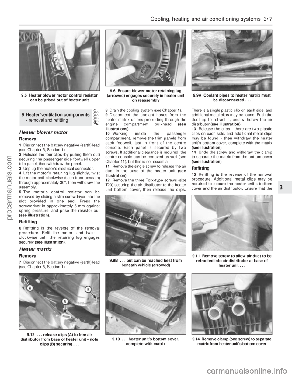
(see illustration).
Refitting
6Refitting is the reverse of the removal
procedure. Refit the motor, and twist it
clockwise until the retaining lug engages
securely (see illustration).
Heater matrix
Removal
7Disconnect the battery negative (earth) lead
(see Chapter 5, Section 1).8Drain the cooling system (see Chapter 1).
9Disconnect the coolant hoses from the
heater matrix unions protruding through the
engine compartment bulkhead (see
illustrations).
10Working inside the passenger
compartment, remove the trim panels from
each footwell, just in front of the centre
console. Each panel is secured by two
screws. If additional clearance is required, the
centre console can be removed as well (see
Chapter 11), but this is not essential.
11Remove the single screw to release the air
duct in the base of the heater unit (see
illustration).
12Remove the three Torx-type screws (size
T20) securing the air distributor to the heater
unit bottom cover, then release the clips.There is a single plastic clip on each side, and
additional metal clips may be found. Push the
duct up to retract it, and withdraw the air
distributor (see illustration).
13Release the clips - there are two plastic
clips on each side, and additional metal clips
may be found - then withdraw the heater
unit’s bottom cover, complete with the matrix
(see illustration).
14Undo the screw and withdraw the clamp
to separate the matrix from the bottom cover
(see illustration).
Refitting
15Refitting is the reverse of the removal
procedure. Additional metal clips may be
required to secure the heater unit’s bottom
cover and the air distributor. Ensure that the
9 Heater/ventilation components
- removal and refitting
Cooling, heating and air conditioning systems 3•7
3
9.12 . . . release clips (A) to free air
distributor from base of heater unit - note
clips (B) securing . . .9.13 . . . heater unit’s bottom cover,
complete with matrix9.14 Remove clamp (one screw) to separate
matrix from heater unit’s bottom cover
9.5 Heater blower motor control resistor
can be prised out of heater unit9.6 Ensure blower motor retaining lug
(arrowed) engages securely in heater unit
on reassembly9.9A Coolant pipes to heater matrix must
be disconnected . . .
9.9B . . . but can be reached best from
beneath vehicle (arrowed)9.11 Remove screw to allow air duct to be
retracted into air distributor at base of
heater unit . . .
procarmanuals.com
Page 96 of 279
duct is lowered from the air distributor and
secured with its screw.
16Refill the cooling system with the proper
mixture of antifreeze and water (see Chapter
1). Start the engine and allow it to reach
normal operating temperature, indicated by
the radiator top hose becoming hot. Recheck
the coolant level and add more if required,
then check for leaks. Check the operation of
the heater.
Pollen filter
17Refer to Chapter 1.
Blower/air conditioning control
Removal
1Disconnect the battery negative (earth) lead
(see Chapter 5, Section 1).
2Remove the ashtray. Referring to the
relevant Sections of Chapter 11, undo the two
upper screws from the centre console and
pull out the cassette storage compartment,
then remove the radio/cassette player.
3Pull the heater control/radio bezel out of the
three clips securing its top edge, pull it
forwards and unplug the switch electrical
connector (where fitted).
4Pull off the heater control knobs, and
remove the screw securing each end of the
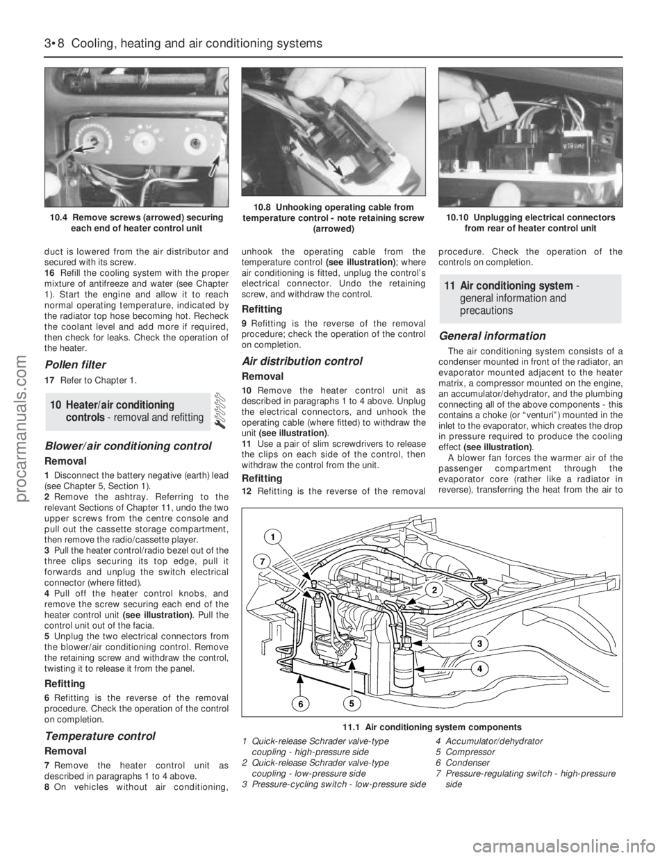
heater control unit (see illustration). Pull the
control unit out of the facia.
5Unplug the two electrical connectors from
the blower/air conditioning control. Remove
the retaining screw and withdraw the control,
twisting it to release it from the panel.
Refitting
6Refitting is the reverse of the removal
procedure. Check the operation of the control
on completion.
Temperature control
Removal
7Remove the heater control unit as
described in paragraphs 1 to 4 above.
8On vehicles without air conditioning,unhook the operating cable from the
temperature control (see illustration); where
air conditioning is fitted, unplug the control’s
electrical connector. Undo the retaining
screw, and withdraw the control.
Refitting
9Refitting is the reverse of the removal
procedure; check the operation of the control
on completion.
Air distribution control
Removal
10Remove the heater control unit as
described in paragraphs 1 to 4 above. Unplug
the electrical connectors, and unhook the
operating cable (where fitted) to withdraw the
unit (see illustration).
11Use a pair of slim screwdrivers to release
the clips on each side of the control, then
withdraw the control from the unit.
Refitting
12Refitting is the reverse of the removalprocedure. Check the operation of the
controls on completion.
General information
The air conditioning system consists of a
condenser mounted in front of the radiator, an
evaporator mounted adjacent to the heater
matrix, a compressor mounted on the engine,
an accumulator/dehydrator, and the plumbing
connecting all of the above components - this
contains a choke (or “venturi”) mounted in the
inlet to the evaporator, which creates the drop
in pressure required to produce the cooling
effect (see illustration).
A blower fan forces the warmer air of the
passenger compartment through the
evaporator core (rather like a radiator in
reverse), transferring the heat from the air to
11 Air conditioning system -
general information and
precautions
10 Heater/air conditioning
controls- removal and refitting
3•8 Cooling, heating and air conditioning systems
10.4 Remove screws (arrowed) securing
each end of heater control unit10.8 Unhooking operating cable from
temperature control - note retaining screw
(arrowed)10.10 Unplugging electrical connectors
from rear of heater control unit
11.1 Air conditioning system components
1 Quick-release Schrader valve-type
coupling - high-pressure side
2 Quick-release Schrader valve-type
coupling - low-pressure side
3 Pressure-cycling switch - low-pressure side4 Accumulator/dehydrator
5 Compressor
6 Condenser
7 Pressure-regulating switch - high-pressure
side
procarmanuals.com
Page 97 of 279
the refrigerant. The liquid refrigerant boils off
into low-pressure vapour, taking the heat with
it when it leaves the evaporator.
Precautions
Warning: The air conditioning
system is under high pressure.
Do not loosen any fittings or
remove any components until
after the system has been discharged. Air
conditioning refrigerant should be properly
discharged into an approved type of
container, at a dealer service department
or an automotive air conditioning repair
facility capable of handling R134a
refrigerant. Always wear eye protection
when disconnecting air conditioning
system fittings.
When an air conditioning system is fitted, it
is necessary to observe the following special
precautions whenever dealing with any part of
the system, its associated components, and
any items which necessitate disconnection of
the system:
(a) While the refrigerant used - R134a - is
less damaging to the environment than
the previously-used R12, it is still a very
dangerous substance. It must not be
allowed into contact with the skin or eyes,
or there is a risk of frostbite. It must also
not be discharged in an enclosed space -
while it is not toxic, there is a risk of
suffocation. The refrigerant is heavier than
air, and so must never be discharged over
a pit.
(b) The refrigerant must not be allowed to
come in contact with a naked flame,
otherwise a poisonous gas will be created
- under certain circumstances, this can
form an explosive mixture with air. For
similar reasons, smoking in the presence
of refrigerant is highly dangerous,
particularly if the vapour is inhaled
through a lighted cigarette.
(c) Never discharge the system to the
atmosphere - R134a is not an ozone-
depleting ChloroFluoroCarbon (CFC) as is
R12, but is instead a hydrofluorocarbon,
which causes environmental damage by
contributing to the “greenhouse effect” if
released into the atmosphere.
(d) R134a refrigerant must notbe mixed with
R12; the system uses different seals (now
green-coloured, previously black) and has
different fittings requiring different tools,
so that there is no chance of the two
types of refrigerant becoming mixed
accidentally.
(e) If for any reason the system must be
disconnected, entrust this task to your
Ford dealer or a refrigeration engineer.
(f) It is essential that the system be
professionally discharged prior to using
any form of heat - welding, soldering,
brazing, etc - in the vicinity of the system,
before having the vehicle oven-dried at a
temperature exceeding 70°C after
repainting, and before disconnecting any
part of the system.Warning: The air conditioning
system is under high pressure.
Do not loosen any fittings or
remove any components until after the
system has been discharged. Air
conditioning refrigerant should be properly
discharged into an approved type of
container, at a dealer service department
or an automotive air conditioning repair
facility capable of handling R134a
refrigerant. Cap or plug the pipe lines as
soon as they are disconnected, to prevent
the entry of moisture. Always wear eye
protection when disconnecting air
conditioning system fittings.
Note: This Section refers to the components
of the air conditioning system itself - refer to
Sections 9 and 10 for details of components
common to the heating/ventilation system.
Condenser
1Have the refrigerant discharged at a dealer
service department or an automotive air
conditioning repair facility.
2Disconnect the battery negative (earth) lead
(see Chapter 5, Section 1).
3Remove the radiator undershield (see
Chapter 1).
4Using the Ford service tool 34-001,
disconnect the refrigerant lines from the
condenser. Immediately cap the open fittings,
to prevent the entry of dirt and moisture.
5Unbolt the condenser (see illustration 7.5)
and lift it out of the vehicle. Store it upright, to
prevent oil loss.
6Refitting is the reverse of removal.
7If a new condenser was installed, add 20 cc
of refrigerant oil to the system.
8Have the system evacuated, charged and
leak-tested by the specialist who discharged
it.
Evaporator
9The evaporator is mounted with the heater
matrix. Apart from the need to have the
refrigerant discharged, and to use Ford
service tools 34-001 and 34-003 to
disconnect the lines, the procedure is as
described in Section 9 of this Chapter.
10On reassembly, if a new evaporator was
installed, add 20 cc of refrigerant oil to the
system.
11Have the system evacuated, charged and
leak-tested by the specialist who discharged
it.
Compressor
12Have the refrigerant discharged at a
dealer service department or an automotive
air conditioning repair facility.
13Disconnect the battery negative (earth)
lead (see Chapter 5, Section 1).
14Remove the radiator undershield (see
Chapter 1).15Remove the auxiliary drivebelt (see
Chapter 1).
16Unbolt the compressor from the cylinder
block/crankcase, press it to one side, and
unscrew the clamping bolt to disconnect the
refrigerant lines. Plug the line connections,
swing the compressor upright, unplug its
electrical connector, then withdraw the
compressor from the vehicle. Note:Keep the
compressor level during handling and storage.
If the compressor has seized, or if you find
metal particles in the refrigerant lines, the
system must be flushed out by an air
conditioning technician, and the
accumulator/dehydrator must be renewed.
17Prior to installation, turn the compressor
clutch centre six times, to disperse any oil that
has collected in the head.
18Refit the compressor in the reverse order
of removal; renew all seals disturbed.
19If you are installing a new compressor,
refer to the compressor manufacturer’s
instructions for adding refrigerant oil to the
system.
20Have the system evacuated, charged and
leak-tested by the specialist that discharged
it.
Accumulator/dehydrator
21Have the refrigerant discharged at a
dealer service department or an automotive
air conditioning repair facility.
22Disconnect the battery negative (earth)
lead (see Chapter 5, Section 1).
23The accumulator/dehydrator, which acts
as a reservoir and filter for the refrigerant, is
located in the left-hand front corner of the
engine compartment. Using the Ford service
tool 34-003, disconnect the refrigerant line
next to the accumulator/dehydrator from the
compressor. Immediately cap the open
fittings, to prevent the entry of dirt and
moisture, then unplug the pressure-cycling
switch electrical connector (see illustration).
24Remove the radiator undershield (see
Chapter 1).
25Unbolt the accumulator/dehydrator from
the front suspension subframe.
26Using the Ford service tool 34-003,
disconnect the lower refrigerant line from the
accumulator/dehydrator. It may be necessary
12 Air conditioning system
components -
removal and refitting
Cooling, heating and air conditioning systems 3•9
3
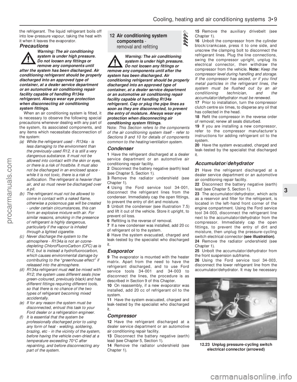
12.23 Unplug pressure-cycling switch
electrical connector (arrowed)
procarmanuals.com
Page 98 of 279
to unscrew the pressure-cycling switch to
allow the use of the tool. Immediately cap the
open fittings, to prevent the entry of dirt and
moisture.
27Withdraw the accumulator/dehydrator.
28Refit the accumulator/dehydrator in the
reverse order of removal; renew all seals
disturbed.
29If you are installing a new accumulator/
dehydrator, refer to the manufacturer’s
instructions for adding refrigerant oil to the
system.
30Have the system evacuated, charged and
leak-tested by the specialist that discharged
it.Pressure-cycling and pressure-
regulating switches
31Have the refrigerant discharged at a
dealer service department or an automotive
air conditioning repair facility.
32Disconnect the battery negative (earth)
lead (see Chapter 5, Section 1).
33Unplug the switch electrical connector,
and unscrew it (see illustration).
34Refitting is the reverse of the removal
procedure; there is no need to top-up the
refrigerant oil.
35Have the system evacuated, charged and
leak-tested by the specialist that discharged
it.
3•10 Cooling, heating and air conditioning systems
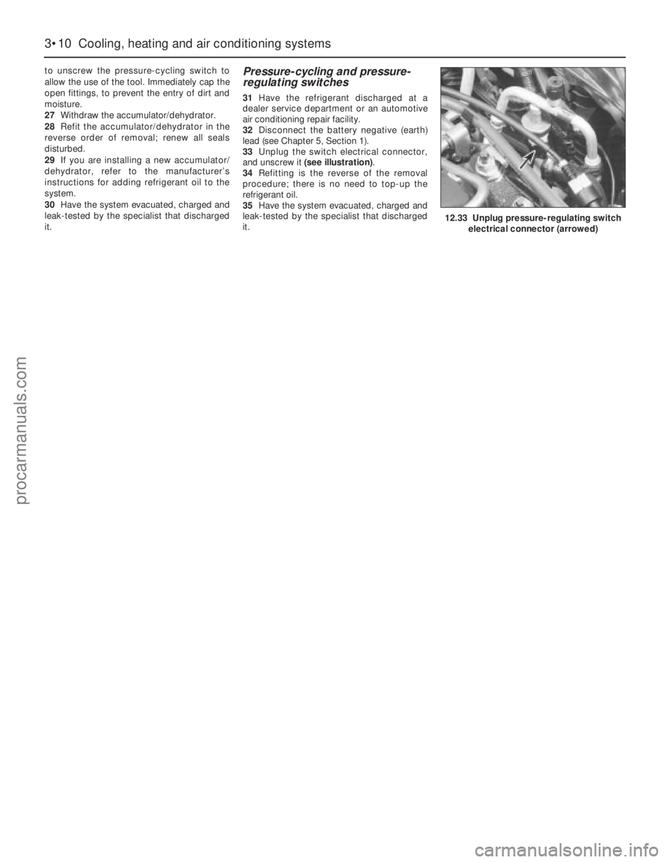
12.33 Unplug pressure-regulating switch
electrical connector (arrowed)
procarmanuals.com
Page 137 of 279
Emissions control systems 6•3
6
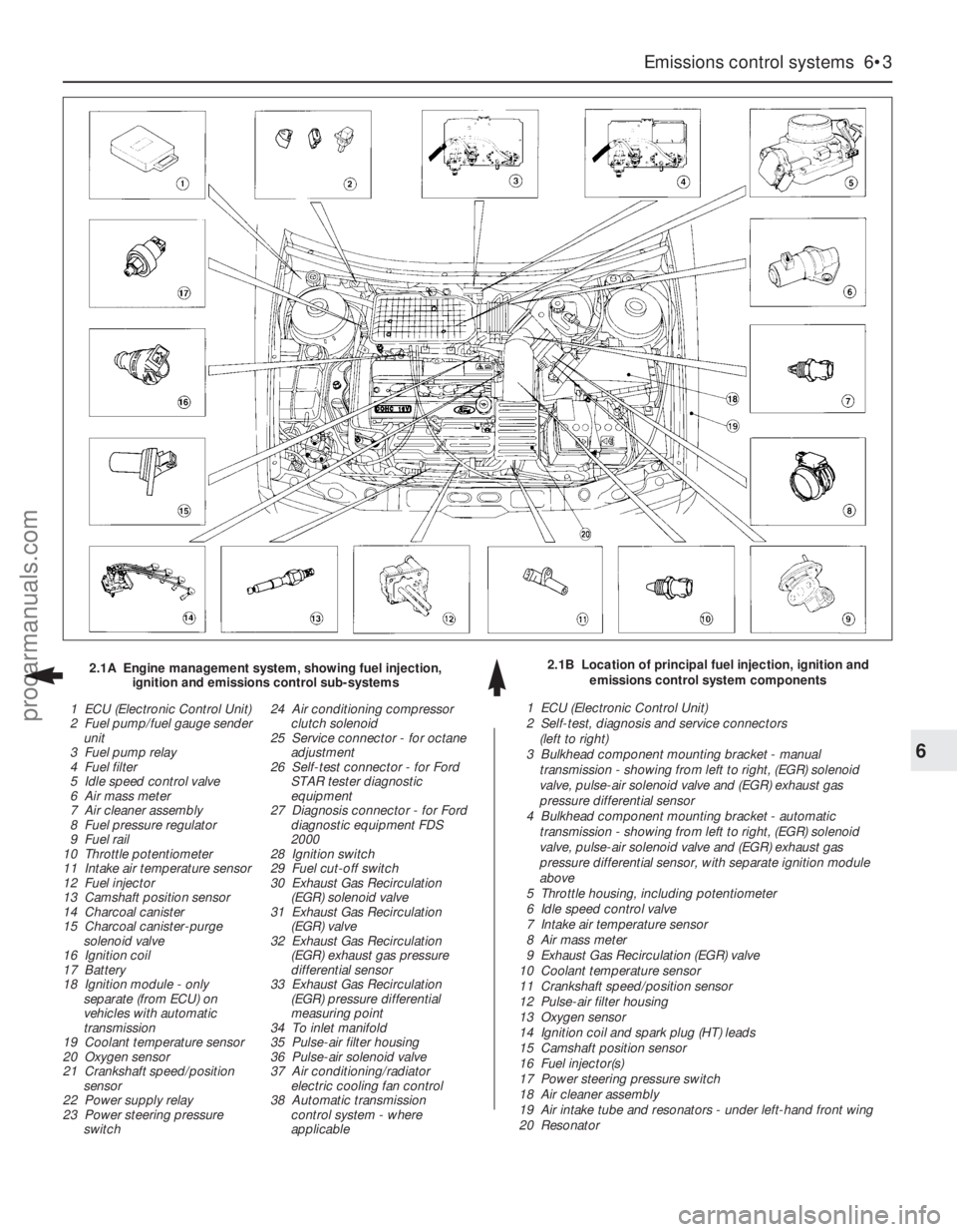
2.1B Location of principal fuel injection, ignition and
emissions control system components 2.1A Engine management system, showing fuel injection,
ignition and emissions control sub-systems
1 ECU (Electronic Control Unit)
2 Fuel pump/fuel gauge sender
unit
3 Fuel pump relay
4 Fuel filter
5 Idle speed control valve
6 Air mass meter
7 Air cleaner assembly
8 Fuel pressure regulator
9 Fuel rail
10 Throttle potentiometer
11 Intake air temperature sensor
12 Fuel injector
13 Camshaft position sensor
14 Charcoal canister
15 Charcoal canister-purge
solenoid valve
16 Ignition coil
17 Battery
18 Ignition module - only
separate (from ECU) on
vehicles with automatic
transmission
19 Coolant temperature sensor
20 Oxygen sensor
21 Crankshaft speed/position
sensor
22 Power supply relay
23 Power steering pressure
switch24 Air conditioning compressor
clutch solenoid
25 Service connector - for octane
adjustment
26 Self-test connector - for Ford
STAR tester diagnostic
equipment
27 Diagnosis connector - for Ford
diagnostic equipment FDS
2000
28 Ignition switch
29 Fuel cut-off switch
30 Exhaust Gas Recirculation
(EGR) solenoid valve
31 Exhaust Gas Recirculation
(EGR) valve
32 Exhaust Gas Recirculation
(EGR) exhaust gas pressure
differential sensor
33 Exhaust Gas Recirculation
(EGR) pressure differential
measuring point
34 To inlet manifold
35 Pulse-air filter housing
36 Pulse-air solenoid valve
37 Air conditioning/radiator
electric cooling fan control
38 Automatic transmission
control system - where
applicable1 ECU (Electronic Control Unit)
2 Self-test, diagnosis and service connectors
(left to right)
3 Bulkhead component mounting bracket - manual
transmission - showing from left to right, (EGR) solenoid
valve, pulse-air solenoid valve and (EGR) exhaust gas
pressure differential sensor
4 Bulkhead component mounting bracket - automatic
transmission - showing from left to right, (EGR) solenoid
valve, pulse-air solenoid valve and (EGR) exhaust gas
pressure differential sensor, with separate ignition module
above
5 Throttle housing, including potentiometer
6 Idle speed control valve
7 Intake air temperature sensor
8 Air mass meter
9 Exhaust Gas Recirculation (EGR) valve
10 Coolant temperature sensor
11 Crankshaft speed/position sensor
12 Pulse-air filter housing
13 Oxygen sensor
14 Ignition coil and spark plug (HT) leads
15 Camshaft position sensor
16 Fuel injector(s)
17 Power steering pressure switch
18 Air cleaner assembly
19 Air intake tube and resonators - under left-hand front wing
20 Resonator
procarmanuals.com
Page 138 of 279
constantly monitors the oxygen content of the
exhaust gas. If the percentage of oxygen in
the exhaust gas is incorrect, an electrical
signal is sent to the ECU. The ECU processes
this information, and then sends a command
to the fuel injection system, telling it to change
the air/fuel mixture; the end result is an air/fuel
mixture ratio which is constantly maintained
at a predetermined ratio, regardless of driving
conditions. This happens in a fraction of a
second, and goes on almost all the time while
the engine is running - the exceptions are that
the ECU cuts out the system and runs the
engine on values pre-programmed
(“mapped”) into its memory both while the
oxygen sensor is reaching its normal
operating temperature after the engine has
been started from cold, and when the throttle
is fully open for full acceleration.
In the event of a sensor malfunction, a
back-up circuit will take over, to provide
driveability until the problem is identified and
fixed.
Precautions
(a) Always disconnect the power by
uncoupling the battery terminals - see
Section 1 of Chapter 5 - before removing
any of the electronic control system’s
electrical connectors.
(b) When installing a battery, be particularly
careful to avoid reversing the positive and
negative battery leads.
(c) Do not subject any components of the
system (especially the ECU) to severe
impact during removal or installation.
(d) Do not be careless during fault diagnosis.
Even slight terminal contact can invalidate
a testing procedure, and damage one of
the numerous transistor circuits.
(e) Never attempt to work on the ECU, to test
it (with any kind of test equipment), or to
open its cover.
(f) If you are inspecting electronic control
system components during rainy weather,
make sure that water does not enter any
part. When washing the engine
compartment, do not spray these parts or
their electrical connectors with water.
General
The various components of the fuel, ignition
and emissions control systems (not forgetting
the same ECU’s control of sub-systems such
as the radiator cooling fan, air conditioning
and automatic transmission, where
appropriate) are so closely interlinked that
diagnosis of a fault in any one component is
virtually impossible using traditional methods.
Working on simpler systems in the past, the
experienced mechanic may well have been
able to use personal skill and knowledge
immediately to pinpoint the cause of a fault, or
quickly to isolate the fault, by elimination;however, with an engine management system
integrated to this degree, this is not likely to
be possible in most instances, because of the
number of symptoms that could arise from
even a minor fault.
So that the causes of faults can be quickly
and accurately traced and rectified, the ECU
is provided with a built-in self-diagnosis
facility, which detects malfunctions in the
system’s components. When a fault occurs,
three things happen: the ECU identifies the
fault, stores a corresponding code in its
memory, and (in most cases) runs the system
using back-up values pre-programmed
(“mapped”) into its memory; some form of
driveability is thus maintained, to enable the
vehicle to be driven to a garage for attention.
Any faults that may have occurred are
indicated in the form of three-digit codes
when the system is connected (via the built-in
diagnosis or self-test connectors, as
appropriate) to special diagnostic equipment -
this points the user in the direction of the
faulty circuit, so that further tests can pinpoint
the exact location of the fault.
Given below is the procedure that would be
followed by a Ford technician to trace a fault
from scratch. Should your vehicle’s engine
management system develop a fault, read
through the procedure and decide how much
you can attempt, depending on your skill and
experience and the equipment available to
you, or whether it would be simpler to have
the vehicle attended to by your local Ford
dealer. If you are concerned about the
apparent complexity of the system, however,
remember the comments made in the fourth
paragraph of Section 1 of this Chapter; the
preliminary checks require nothing but care,
patience and a few minor items of equipment,
and may well eliminate the majority of faults.
(a) Preliminary checks
(b) Fault code read-out *
(c) Check ignition timing and base idle
speed. Recheck fault codes to establish
whether fault has been cured or not *
(d) Carry out basic check of ignition system
components. Recheck fault codes to
establish whether fault has been cured or
not *
(e) Carry out basic check of fuel system
components. Recheck fault codes to
establish whether fault has been cured or
not *
(f) If fault is still not located, carry out system
test *
Note:Operations marked with an asterisk
require special test equipment.
Preliminary checks
Note:When carrying out these checks to
trace a fault, remember that if the fault has
appeared only a short time after any part of
the vehicle has been serviced or overhauled,
the first place to check is where that work was
carried out, however unrelated it may appear,
to ensure that no carelessly-refitted
components are causing the problem.If you are tracing the cause of a “partial”
engine fault, such as lack of performance, in
addition to the checks outlined below, check
the compression pressures (see Part A of
Chapter 2) and bear in mind the possibility
that one of the hydraulic tappets might be
faulty, producing an incorrect valve clearance.
Check also that the fuel filter has been
renewed at the recommended intervals.
If the system appears completely dead,
remember the possibility that the
alarm/inhibitor system may be responsible.
1The first check for anyone without special
test equipment is to switch on the ignition,
and to listen for the fuel pump (the sound of
an electric motor running, audible from
beneath the rear seats); assuming there is
sufficient fuel in the tank, the pump should
start and run for approximately one or two
seconds, then stop, each time the ignition is
switched on. If the pump runs continuously all
the time the ignition is switched on, the
electronic control system is running in the
back-up (or “limp-home”) mode referred to by
Ford as “Limited Operation Strategy” (LOS).
This almost certainly indicates a fault in the
ECU itself, and the vehicle should therefore be
taken to a Ford dealer for a full test of the
complete system using the correct diagnostic
equipment; do not waste time trying to test
the system without such facilities.
2If the fuel pump is working correctly (or not
at all), a considerable amount of fault
diagnosis is still possible without special test
equipment. Start the checking procedure as
follows.
3Open the bonnet and check the condition
of the battery connections - remake the
connections or renew the leads if a fault is
found (Chapter 5). Use the same techniques
to ensure that all earth points in the engine
compartment provide good electrical contact
through clean, metal-to-metal joints, and that
all are securely fastened. (In addition to the
earth connection at the engine lifting eye and
that from the transmission to the
body/battery, there is one earth connection
behind each headlight assembly, and one
below the power steering fluid reservoir.)
4Referring to the information given in
Chapter 12 and in the wiring diagrams at the
back of this manual, check that all fuses
protecting the circuits related to the engine
management system are in good condition.
Fit new fuses if required; while you are there,
check that all relays are securely plugged into
their sockets.
5Next work methodically around the engine
compartment, checking all visible wiring, and
the connections between sections of the
wiring loom. What you are looking for at this
stage is wiring that is obviously damaged by
chafing against sharp edges, or against
moving suspension/transmission components
and/or the auxiliary drivebelt, by being
trapped or crushed between carelessly-
refitted components, or melted by being
forced into contact with hot engine castings,
3 Diagnosis system -
general information
6•4 Emissions control systems
procarmanuals.com