1993 FORD MONDEO battery location
[x] Cancel search: battery locationPage 102 of 279
housing stud) and the sealing O-ring in the
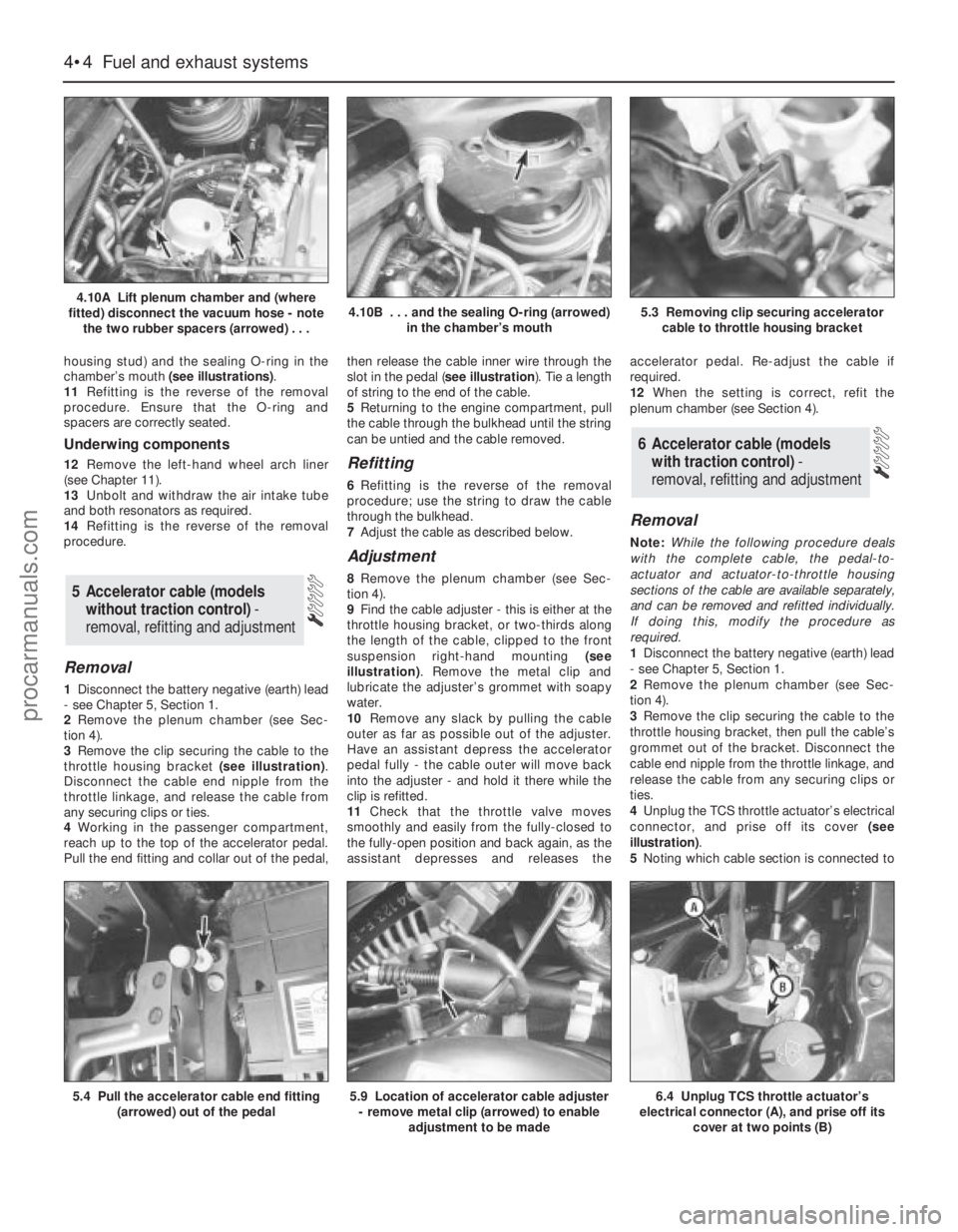
chamber’s mouth (see illustrations).
11Refitting is the reverse of the removal
procedure. Ensure that the O-ring and
spacers are correctly seated.
Underwing components
12Remove the left-hand wheel arch liner
(see Chapter 11).
13Unbolt and withdraw the air intake tube
and both resonators as required.
14Refitting is the reverse of the removal
procedure.
Removal
1Disconnect the battery negative (earth) lead
- see Chapter 5, Section 1.
2Remove the plenum chamber (see Sec-
tion 4).
3Remove the clip securing the cable to the
throttle housing bracket (see illustration).
Disconnect the cable end nipple from the
throttle linkage, and release the cable from
any securing clips or ties.
4Working in the passenger compartment,
reach up to the top of the accelerator pedal.
Pull the end fitting and collar out of the pedal,then release the cable inner wire through the
slot in the pedal (see illustration). Tie a length
of string to the end of the cable.
5Returning to the engine compartment, pull
the cable through the bulkhead until the string
can be untied and the cable removed.
Refitting
6Refitting is the reverse of the removal
procedure; use the string to draw the cable
through the bulkhead.
7Adjust the cable as described below.
Adjustment
8Remove the plenum chamber (see Sec-
tion 4).
9Find the cable adjuster - this is either at the
throttle housing bracket, or two-thirds along
the length of the cable, clipped to the front
suspension right-hand mounting (see
illustration). Remove the metal clip and
lubricate the adjuster’s grommet with soapy
water.
10Remove any slack by pulling the cable
outer as far as possible out of the adjuster.
Have an assistant depress the accelerator
pedal fully - the cable outer will move back
into the adjuster - and hold it there while the
clip is refitted.
11Check that the throttle valve moves
smoothly and easily from the fully-closed to
the fully-open position and back again, as the
assistant depresses and releases theaccelerator pedal. Re-adjust the cable if
required.
12When the setting is correct, refit the
plenum chamber (see Section 4).
Removal
Note:While the following procedure deals
with the complete cable, the pedal-to-
actuator and actuator-to-throttle housing
sections of the cable are available separately,
and can be removed and refitted individually.
If doing this, modify the procedure as
required.
1Disconnect the battery negative (earth) lead
- see Chapter 5, Section 1.
2Remove the plenum chamber (see Sec-
tion 4).
3Remove the clip securing the cable to the
throttle housing bracket, then pull the cable’s
grommet out of the bracket. Disconnect the
cable end nipple from the throttle linkage, and
release the cable from any securing clips or
ties.
4Unplug the TCS throttle actuator’s electrical
connector, and prise off its cover (see
illustration).
5Noting which cable section is connected to
6 Accelerator cable (models
with traction control)-
removal, refitting and adjustment
5 Accelerator cable (models
without traction control) -
removal, refitting and adjustment
4•4 Fuel and exhaust systems
4.10A Lift plenum chamber and (where
fitted) disconnect the vacuum hose - note
the two rubber spacers (arrowed) . . .4.10B . . . and the sealing O-ring (arrowed)
in the chamber’s mouth5.3 Removing clip securing accelerator
cable to throttle housing bracket
5.4 Pull the accelerator cable end fitting
(arrowed) out of the pedal5.9 Location of accelerator cable adjuster
- remove metal clip (arrowed) to enable
adjustment to be made6.4 Unplug TCS throttle actuator’s
electrical connector (A), and prise off its
cover at two points (B)
procarmanuals.com
Page 106 of 279
(b) On Estate models, slacken the clamp
immediately above the rear anti-roll bar,
and work the hose off the filler neck stub
(see illustration).
8Unscrew the six retaining nuts, and
withdraw the exhaust system’s rear heat
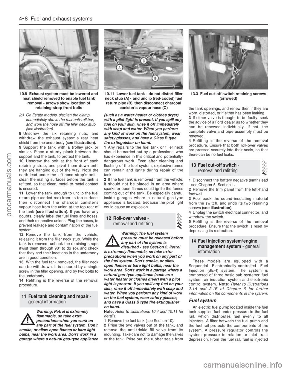
shield from the underbody (see illustration).
9Support the tank with a trolley jack or
similar. Place a sturdy plank between the
support and the tank, to protect the tank.
10Unscrew the bolt at the front of each
retaining strap, and pivot them down until
they are hanging out of the way. Note the
earth lead under the left-hand strap’s bolt -
clean the mating surfaces before the tank is
refitted, so that clean, metal-to-metal contact
is ensured.
11Lower the tank enough to unclip the fuel
return pipe (coded red) from its top surface,
then disconnect the charcoal canister’s
vapour hose from the union at the top rear of
the tank (see illustration). If you have any
doubts, clearly label the fuel lines and hoses,
and their respective unions. Plug the hoses, to
prevent leakage and contamination of the fuel
system.
12Remove the tank from the vehicle,
releasing it from the filler neck stub. While the
tank is removed, unhook the retaining straps
(twist them through 90° to do so), and check
that they and their locations in the underbody
are in good condition.
13With the fuel tank removed, the filler neck
can be withdrawn. It is secured by a single
screw in the filler opening, and by two bolts to
the underbody.
14Refitting is the reverse of the removal
procedure.
Warning: Petrol is extremely
flammable, so take extra
precautions when you work on
any part of the fuel system. Don’t
smoke, or allow open flames or bare light
bulbs, near the work area. Don’t work in a
garage where a natural gas-type appliance(such as a water heater or clothes dryer)
with a pilot light is present. If you spill any
fuel on your skin, rinse it off immediately
with soap and water. When you perform
any kind of work on the fuel system, wear
safety glasses, and have a Class B type
fire extinguisher on hand.
1Any repairs to the fuel tank or filler neck
should be carried out by a professional who
has experience in this critical and potentially-
dangerous work. Even after cleaning and
flushing of the fuel system, explosive fumes
can remain and ignite during repair of the
tank.
2If the fuel tank is removed from the vehicle,
it should not be placed in an area where
sparks or open flames could ignite the fumes
coming out of the tank. Be especially careful
inside garages where a natural gas-type
appliance is located, because the pilot light
could cause an explosion.
Warning: The fuel system
pressure must be released before
any part of the system is
disturbed - see Section 2. Petrol
is extremely flammable, so take extra
precautions when you work on any part of
the fuel system. Don’t smoke, or allow
open flames or bare light bulbs, near the
work area. Don’t work in a garage where a
natural gas-type appliance (such as a
water heater or clothes dryer) with a pilot
light is present. If you spill any fuel on your
skin, rinse it off immediately with soap and
water. When you perform any kind of work
on the fuel system, wear safety glasses,
and have a Class B type fire extinguisher
on hand.
Note: Refer to illustrations 10.4 and 10.11 for
details.
1Remove the fuel tank (see Section 10).
2Prise the two valves out of the tank, and
remove the anti-trickle fill valve from its
mounting. Take care not to damage the valves
or the tank. Prise out the rubber seals fromthe tank openings, and renew then if they are
worn, distorted, or if either has been leaking.
3If either valve is thought to be faulty, seek
the advice of a Ford dealer as to whether they
can be renewed individually. If not, the
complete valve and pipe assembly must be
renewed.
4Refitting is the reverse of the removal
procedure. Ensure that both roll-over valves
are pressed securely into their seals, so that
there can be no fuel leaks.
1Disconnect the battery negative (earth) lead
- see Chapter 5, Section 1.
2Remove the trim panel from the left-hand
footwell.
3Peel back the sound-insulating material
from the switch, and undo its two retaining
screws (see illustration).
4Unplug the switch electrical connector, and
withdraw the switch.
5Refitting is the reverse of the removal
procedure. Ensure that the switch is reset by
depressing its red button.
These models are equipped with a
Sequential Electronically-controlled Fuel
Injection (SEFI) system. The system is
composed of three basic sub-systems: fuel
system, air induction system and electronic
control system. Note:Refer to illustrations
2.1A and 2.1B of Chapter 6 for further
information on the components of the system.
Fuel system
An electric fuel pump located inside the fuel
tank supplies fuel under pressure to the fuel
rail, which distributes fuel evenly to all
injectors. A filter between the fuel pump and
the fuel rail protects the components of the
system. A pressure regulator controls the
system pressure in relation to inlet tract
depression. From the fuel rail, fuel is injected
14 Fuel injection system/engine
management system - general
information
13 Fuel cut-off switch -
removal and refitting
12 Roll-over valves -
removal and refitting
11 Fuel tank cleaning and repair -
general information
4•8 Fuel and exhaust systems
10.8 Exhaust system must be lowered and
heat shield removed to enable fuel tank
removal - arrows show location of
retaining strap front bolts10.11 Lower fuel tank - do not distort filler
neck stub (A) - and unclip (red-coded) fuel
return pipe (B), then disconnect charcoal
canister’s vapour hose (C)13.3 Fuel cut-off switch retaining screws
(arrowed)
procarmanuals.com
Page 109 of 279
rings, and intend to re-use the same injectors,
remove the old nose seal and O-rings, and
discard them.
22Further testing of the injector(s) is beyond
the scope of the home mechanic. If you are in
doubt as to the status of any injector(s), it can
be tested at a dealer service department.
23Refitting is the reverse of the removal
procedure, noting the following points:
(a) Lubricate each nose seal and O-ring with
clean engine oil on installation.
(b) Locate each injector carefully in the fuel
rail recess, ensuring that the locating tab
on the injector head fits into the slot
provided in the rail. Tighten the bolts to
the specified torque.
(c) Fit a new seal to each fuel rail nose, and
ensure the seals are not displaced as the
rail is refitted. Ensure that the fuel rail is
settled fully in the manifold before
tightening the three bolts evenly and to
the torque wrench setting specified.
(d) Fasten the fuel feed and return quick-
release couplings as described in Sec-
tion 3.
(e) Ensure that the breather hose, vacuum
hose and wiring are routed correctly, and
secured on reconnection by any clips or
ties provided.
(f) On completion, switch the ignition on and
off five times, to activate the fuel pump and
pressurise the system, without cranking
the engine. Check for signs of fuel leaks
around all disturbed unions and joints
before attempting to start the engine.
Fuel pressure regulator
Check
24Refer to the fuel pump/fuel pressure
check procedure (see Section 8).
Renewal
25Relieve the residual pressure in the fuel
system (see Section 2), and equalise tank
pressure by removing the fuel filler cap.
Warning: This procedure will
merely relieve the increased
pressure necessary for the engine
to run - remember that fuel will
still be present in the system components,
and take precautions accordingly before
disconnecting any of them.26Disconnect the battery negative (earth)
lead - see Chapter 5, Section 1.
27Remove the plenum chamber (see
Section 4).
28Disconnect the vacuum hose from the
regulator.
29Unscrew the two regulator retaining bolts,
place a wad of clean rag to soak up any spilt
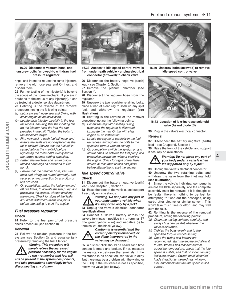
fuel, and withdraw the regulator (see
illustration).
30Refitting is the reverse of the removal
procedure, noting the following points:
(a) Renew the regulator sealing O-ring
whenever the regulator is disturbed.
Lubricate the new O-ring with clean
engine oil on installation.
(b) Locate the regulator carefully in the fuel
rail recess, and tighten the bolts to the
specified torque wrench setting.
(c) On completion, switch the ignition on and
off five times, to activate the fuel pump and
pressurise the system, without cranking
the engine. Check for signs of fuel leaks
around all disturbed unions and joints
before attempting to start the engine.
Idle speed control valve
Check
31Disconnect the battery negative (earth)
lead - see Chapter 5, Section 1.
32Raise the front of the vehicle, and support
it securely on axle stands.
Warning: Do not place any part of
your body under a vehicle when
it’s supported only by a jack!
33Unplug the valve’s electrical connector
(see illustration).
34Connect a 12-volt battery across the
valve’s terminals - positive (+) to terminal 37
(the green/yellow wire) and negative (-) to
terminal 21 (the black/yellow).
Caution: It is essential that the
correct polarity is observed, or
the diode incorporated in the
valve may be damaged.
35A distinct click should be heard each time
contact is made and broken. If not, measure
the resistance between the terminals. If the
resistance is as specified, the valve is okay
(but there may be a problem with the wiring or
the ECU). If the resistance is not as specified,
renew the valve (see below).36Plug in the valve’s electrical connector.
Renewal
37Disconnect the battery negative (earth)
lead - see Chapter 5, Section 1.
38Raise the front of the vehicle, and support
it securely on axle stands.
Warning: Do not place any part of
your body under a vehicle when
it’s supported only by a jack!
39Unplug the valve’s electrical connector.
40Unscrew the two retaining bolts, and
withdraw the valve from the inlet manifold
(see illustration).
41Since the valve’s individual components
are not available separately, and the complete
assembly must be renewed if it is thought to
be faulty, there is nothing to be lost by
attempting to flush out the passages, using
carburettor cleaner or similar solvent. This
won’t take much time or effort, and may well
cure the fault.
42Refitting is the reverse of the removal
procedure, noting the following points:
(a) Clean the mating surfaces carefully, and
always fit a new gasket whenever the
valve is disturbed.
(b) Tighten the bolts evenly and to the
specified torque wrench setting.
(c) Once the wiring and battery are
reconnected, start the engine and allow it
to idle. When it has reached normal
operating temperature, check that the idle
speed is stable, and that no induction (air)
leaks are evident. Switch on all electrical
loads (headlights, heated rear window,
etc), and check that the idle speed is still
correct.
Fuel and exhaust systems 4•11
4
16.43 Location of idle-increase solenoid
valve (A) and diode (B)
16.29 Disconnect vacuum hose, and
unscrew bolts (arrowed) to withdraw fuel
pressure regulator16.33 Access to idle speed control valve is
from underneath vehicle - unplug electrical
connector (arrowed) to check valve16.40 Unscrew bolts (arrowed) to remove
idle speed control valve
procarmanuals.com
Page 114 of 279
3Using an ohmmeter, measure the
resistance of the coil’s primary windings,
connecting the meter between the coil’s
terminal pins as follows. Measure first from
one outer pin to the centre pin, then from the
other outer pin to the centre. Compare your
readings with the coil primary resistance listed
in the Specifications Section at the beginning
of this Chapter.
4Disconnect the spark plug (HT) leads - note
their connections or label them carefully, as
described in Chapter 1. Use the meter to
check that there is continuity (ie, a resistance
corresponding to that of the coil secondary
winding) between each pair of (HT) lead
terminals; Nos 1 and 4 terminals are
connected by their secondary winding, as are
Nos 2 and 3. Now switch to the highest
resistance scale, and check that there is no
continuity between either pair of terminals and
the other - ie, there should be infinite
resistance between terminals 1 and 2, or 4
and 3 - and between any terminal and earth.
5If either of the above tests yield resistance
values outside the specified amount, or
results other than those described, renew the
coil. Any further testing should be left to a
dealer service department or other qualified
repair facility.
Removal and refitting
6Disconnect the battery negative (earth) lead
- see Section 1.
7Remove the air mass meter and resonator -
refer to Chapter 4.
8Unplug the electrical connector from each
side of the coil, then disconnect the spark
plug (HT) leads - note their connections or
label them carefully, as described in Chapter
1.
9Undo the two screws securing the EGR
pipe to the coil bracket, then remove the coil
mounting (Torx-type) screws. Withdraw the
coil assembly from the cylinder head (see
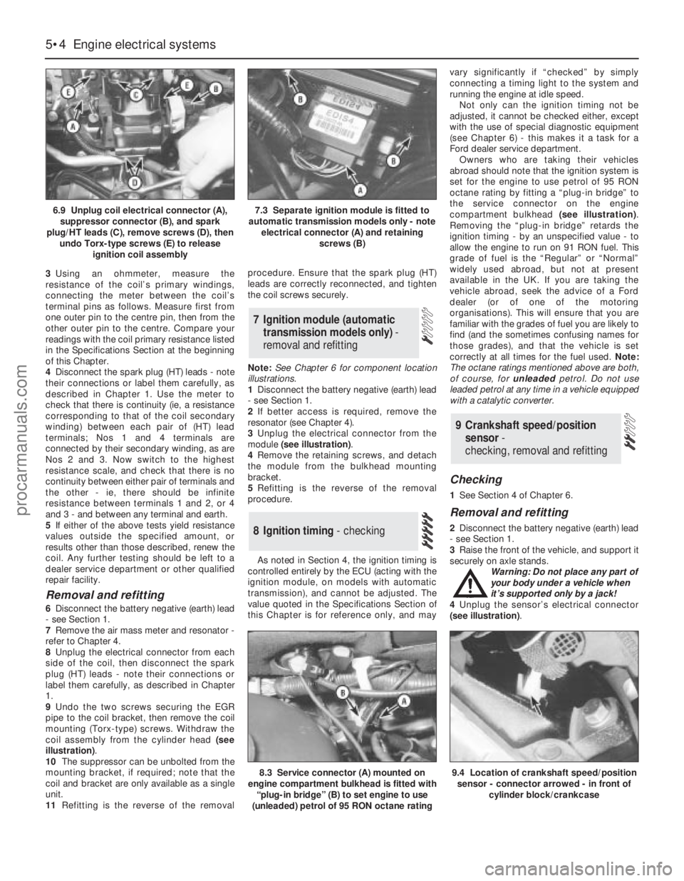
illustration).
10The suppressor can be unbolted from the
mounting bracket, if required; note that the
coil and bracket are only available as a single
unit.
11Refitting is the reverse of the removalprocedure. Ensure that the spark plug (HT)
leads are correctly reconnected, and tighten
the coil screws securely.
Note:See Chapter 6 for component location
illustrations.
1Disconnect the battery negative (earth) lead
- see Section 1.
2If better access is required, remove the
resonator (see Chapter 4).
3Unplug the electrical connector from the
module (see illustration).
4Remove the retaining screws, and detach
the module from the bulkhead mounting
bracket.
5Refitting is the reverse of the removal
procedure.
As noted in Section 4, the ignition timing is
controlled entirely by the ECU (acting with the
ignition module, on models with automatic
transmission), and cannot be adjusted. The
value quoted in the Specifications Section of
this Chapter is for reference only, and mayvary significantly if “checked” by simply
connecting a timing light to the system and
running the engine at idle speed.
Not only can the ignition timing not be
adjusted, it cannot be checked either, except
with the use of special diagnostic equipment
(see Chapter 6) - this makes it a task for a
Ford dealer service department.
Owners who are taking their vehicles
abroad should note that the ignition system is
set for the engine to use petrol of 95 RON
octane rating by fitting a “plug-in bridge” to
the service connector on the engine
compartment bulkhead (see illustration).
Removing the “plug-in bridge” retards the
ignition timing - by an unspecified value - to
allow the engine to run on 91 RON fuel. This
grade of fuel is the “Regular” or “Normal”
widely used abroad, but not at present
available in the UK. If you are taking the
vehicle abroad, seek the advice of a Ford
dealer (or of one of the motoring
organisations). This will ensure that you are
familiar with the grades of fuel you are likely to
find (and the sometimes confusing names for
those grades), and that the vehicle is set
correctly at all times for the fuel used. Note:
The octane ratings mentioned above are both,
of course, for unleadedpetrol. Do not use
leaded petrol at any time in a vehicle equipped
with a catalytic converter.
Checking
1See Section 4 of Chapter 6.
Removal and refitting
2Disconnect the battery negative (earth) lead
- see Section 1.
3Raise the front of the vehicle, and support it
securely on axle stands.
Warning: Do not place any part of
your body under a vehicle when
it’s supported only by a jack!
4Unplug the sensor’s electrical connector
(see illustration).
9 Crankshaft speed/position
sensor-
checking, removal and refitting
8 Ignition timing - checking
7 Ignition module (automatic
transmission models only) -
removal and refitting
5•4 Engine electrical systems
6.9 Unplug coil electrical connector (A),
suppressor connector (B), and spark
plug/HT leads (C), remove screws (D), then
undo Torx-type screws (E) to release
ignition coil assembly7.3 Separate ignition module is fitted to
automatic transmission models only - note
electrical connector (A) and retaining
screws (B)
8.3 Service connector (A) mounted on
engine compartment bulkhead is fitted with
“plug-in bridge” (B) to set engine to use
(unleaded) petrol of 95 RON octane rating9.4 Location of crankshaft speed/position
sensor - connector arrowed - in front of
cylinder block/crankcase
procarmanuals.com
Page 116 of 279
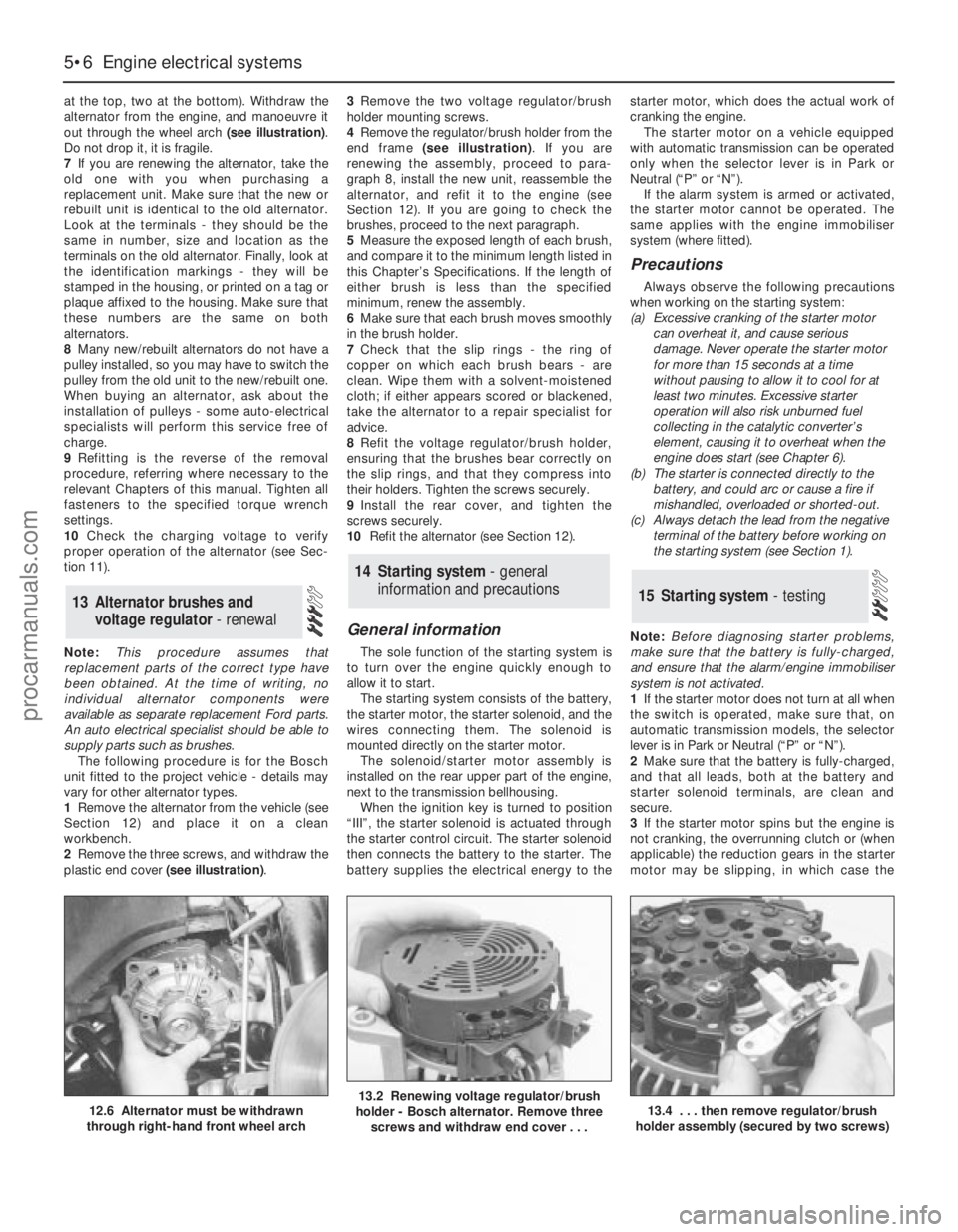
at the top, two at the bottom). Withdraw the
alternator from the engine, and manoeuvre it
out through the wheel arch (see illustration).
Do not drop it, it is fragile.
7If you are renewing the alternator, take the
old one with you when purchasing a
replacement unit. Make sure that the new or
rebuilt unit is identical to the old alternator.
Look at the terminals - they should be the
same in number, size and location as the
terminals on the old alternator. Finally, look at
the identification markings - they will be
stamped in the housing, or printed on a tag or
plaque affixed to the housing. Make sure that
these numbers are the same on both
alternators.
8Many new/rebuilt alternators do not have a
pulley installed, so you may have to switch the
pulley from the old unit to the new/rebuilt one.
When buying an alternator, ask about the
installation of pulleys - some auto-electrical
specialists will perform this service free of
charge.
9Refitting is the reverse of the removal
procedure, referring where necessary to the
relevant Chapters of this manual. Tighten all
fasteners to the specified torque wrench
settings.
10Check the charging voltage to verify
proper operation of the alternator (see Sec-
tion 11).
Note:This procedure assumes that
replacement parts of the correct type have
been obtained. At the time of writing, no
individual alternator components were
available as separate replacement Ford parts.
An auto electrical specialist should be able to
supply parts such as brushes.
The following procedure is for the Bosch
unit fitted to the project vehicle - details may
vary for other alternator types.
1Remove the alternator from the vehicle (see
Section 12) and place it on a clean
workbench.
2Remove the three screws, and withdraw the
plastic end cover (see illustration).3Remove the two voltage regulator/brush
holder mounting screws.
4Remove the regulator/brush holder from the
end frame (see illustration). If you are
renewing the assembly, proceed to para-
graph 8, install the new unit, reassemble the
alternator, and refit it to the engine (see
Section 12). If you are going to check the
brushes, proceed to the next paragraph.
5Measure the exposed length of each brush,
and compare it to the minimum length listed in
this Chapter’s Specifications. If the length of
either brush is less than the specified
minimum, renew the assembly.
6Make sure that each brush moves smoothly
in the brush holder.
7Check that the slip rings - the ring of
copper on which each brush bears - are
clean. Wipe them with a solvent-moistened
cloth; if either appears scored or blackened,
take the alternator to a repair specialist for
advice.
8Refit the voltage regulator/brush holder,
ensuring that the brushes bear correctly on
the slip rings, and that they compress into
their holders. Tighten the screws securely.
9Install the rear cover, and tighten the
screws securely.
10Refit the alternator (see Section 12).
General information
The sole function of the starting system is
to turn over the engine quickly enough to
allow it to start.
The starting system consists of the battery,
the starter motor, the starter solenoid, and the
wires connecting them. The solenoid is
mounted directly on the starter motor.
The solenoid/starter motor assembly is
installed on the rear upper part of the engine,
next to the transmission bellhousing.
When the ignition key is turned to position
“III”, the starter solenoid is actuated through
the starter control circuit. The starter solenoid
then connects the battery to the starter. The
battery supplies the electrical energy to thestarter motor, which does the actual work of
cranking the engine.
The starter motor on a vehicle equipped
with automatic transmission can be operated
only when the selector lever is in Park or
Neutral (“P” or “N”).
If the alarm system is armed or activated,
the starter motor cannot be operated. The
same applies with the engine immobiliser
system (where fitted).
Precautions
Always observe the following precautions
when working on the starting system:
(a) Excessive cranking of the starter motor
can overheat it, and cause serious
damage. Never operate the starter motor
for more than 15 seconds at a time
without pausing to allow it to cool for at
least two minutes. Excessive starter
operation will also risk unburned fuel
collecting in the catalytic converter’s
element, causing it to overheat when the
engine does start (see Chapter 6).
(b) The starter is connected directly to the
battery, and could arc or cause a fire if
mishandled, overloaded or shorted-out.
(c) Always detach the lead from the negative
terminal of the battery before working on
the starting system (see Section 1).
Note:Before diagnosing starter problems,
make sure that the battery is fully-charged,
and ensure that the alarm/engine immobiliser
system is not activated.
1If the starter motor does not turn at all when
the switch is operated, make sure that, on
automatic transmission models, the selector
lever is in Park or Neutral (“P” or “N”).
2Make sure that the battery is fully-charged,
and that all leads, both at the battery and
starter solenoid terminals, are clean and
secure.
3If the starter motor spins but the engine is
not cranking, the overrunning clutch or (when
applicable) the reduction gears in the starter
motor may be slipping, in which case the
15 Starting system - testing
14 Starting system - general
information and precautions
13 Alternator brushes and
voltage regulator - renewal
5•6 Engine electrical systems
12.6 Alternator must be withdrawn
through right-hand front wheel arch13.2 Renewing voltage regulator/brush
holder - Bosch alternator. Remove three
screws and withdraw end cover . . .13.4 . . . then remove regulator/brush
holder assembly (secured by two screws)
procarmanuals.com
Page 128 of 279
10Bleed the brake circuit according to the
procedure given in Section 15. Make sure
there are no leaks from the hose connections.
Test the brakes carefully before returning the
vehicle to normal service.
Refer to Section 4 (front disc inspection).
Once the rear caliper is removed, the
procedure is the same.
Removal
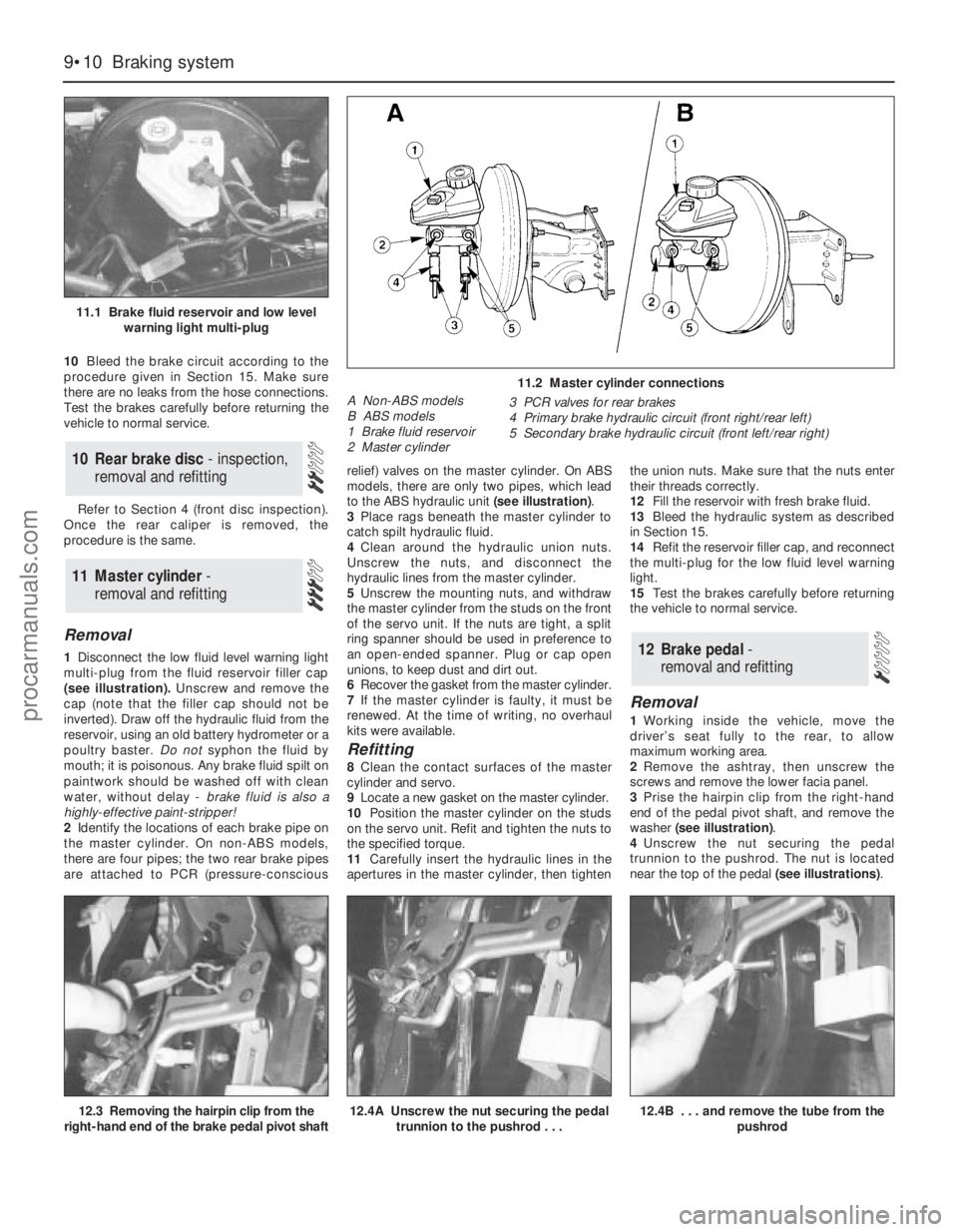
1Disconnect the low fluid level warning light
multi-plug from the fluid reservoir filler cap
(see illustration).Unscrew and remove the
cap (note that the filler cap should not be
inverted). Draw off the hydraulic fluid from the
reservoir, using an old battery hydrometer or a
poultry baster. Do notsyphon the fluid by
mouth; it is poisonous. Any brake fluid spilt on
paintwork should be washed off with clean
water, without delay - brake fluid is also a
highly-effective paint-stripper!
2Identify the locations of each brake pipe on
the master cylinder. On non-ABS models,
there are four pipes; the two rear brake pipes
are attached to PCR (pressure-consciousrelief) valves on the master cylinder. On ABS
models, there are only two pipes, which lead
to the ABS hydraulic unit (see illustration).
3Place rags beneath the master cylinder to
catch spilt hydraulic fluid.
4Clean around the hydraulic union nuts.
Unscrew the nuts, and disconnect the
hydraulic lines from the master cylinder.
5Unscrew the mounting nuts, and withdraw
the master cylinder from the studs on the front
of the servo unit. If the nuts are tight, a split
ring spanner should be used in preference to
an open-ended spanner. Plug or cap open
unions, to keep dust and dirt out.
6Recover the gasket from the master cylinder.
7If the master cylinder is faulty, it must be
renewed. At the time of writing, no overhaul
kits were available.
Refitting
8Clean the contact surfaces of the master
cylinder and servo.
9Locate a new gasket on the master cylinder.
10Position the master cylinder on the studs
on the servo unit. Refit and tighten the nuts to
the specified torque.
11Carefully insert the hydraulic lines in the
apertures in the master cylinder, then tightenthe union nuts. Make sure that the nuts enter
their threads correctly.
12Fill the reservoir with fresh brake fluid.
13Bleed the hydraulic system as described
in Section 15.
14Refit the reservoir filler cap, and reconnect
the multi-plug for the low fluid level warning
light.
15Test the brakes carefully before returning
the vehicle to normal service.
Removal
1Working inside the vehicle, move the
driver’s seat fully to the rear, to allow
maximum working area.
2Remove the ashtray, then unscrew the
screws and remove the lower facia panel.
3Prise the hairpin clip from the right-hand
end of the pedal pivot shaft, and remove the
washer (see illustration).
4Unscrew the nut securing the pedal
trunnion to the pushrod. The nut is located
near the top of the pedal (see illustrations).
12 Brake pedal-
removal and refitting
11 Master cylinder -
removal and refitting
10 Rear brake disc - inspection,
removal and refitting
9•10 Braking system
11.1 Brake fluid reservoir and low level
warning light multi-plug
11.2 Master cylinder connections
A Non-ABS models
B ABS models
1 Brake fluid reservoir
2 Master cylinder3 PCR valves for rear brakes
4 Primary brake hydraulic circuit (front right/rear left)
5 Secondary brake hydraulic circuit (front left/rear right)
12.3 Removing the hairpin clip from the
right-hand end of the brake pedal pivot shaft12.4A Unscrew the nut securing the pedal
trunnion to the pushrod . . .12.4B . . . and remove the tube from the
pushrod
procarmanuals.com
Page 131 of 279
and remove the clevis pin securing the servo
unit pushrod to the pedal cross-link arm.
7On left-hand drive models, unscrew the nut
securing the pedal trunnion to the servo unit
pushrod inside the passenger compartment.
The nut is located near the top of the pedal,
and is accessible through an access hole. For
improved access, remove the lower facia
panel first.
8Withdraw the servo unit from the bulkhead,
and remove it from the engine compartment.
On left-hand drive models, take care not to
damage the bulkhead rubber grommet as the
pushrod passes through it.
9Note that the servo unit cannot be
dismantled for repair or overhaul and, if faulty,
must be renewed.
Refitting
10Refitting is a reversal of the removal
procedure. Refer to Section 11 for details of
refitting the master cylinder.
Removal
1Depress the brake pedal four or five times,
to dissipate any remaining vacuum from the
servo unit.
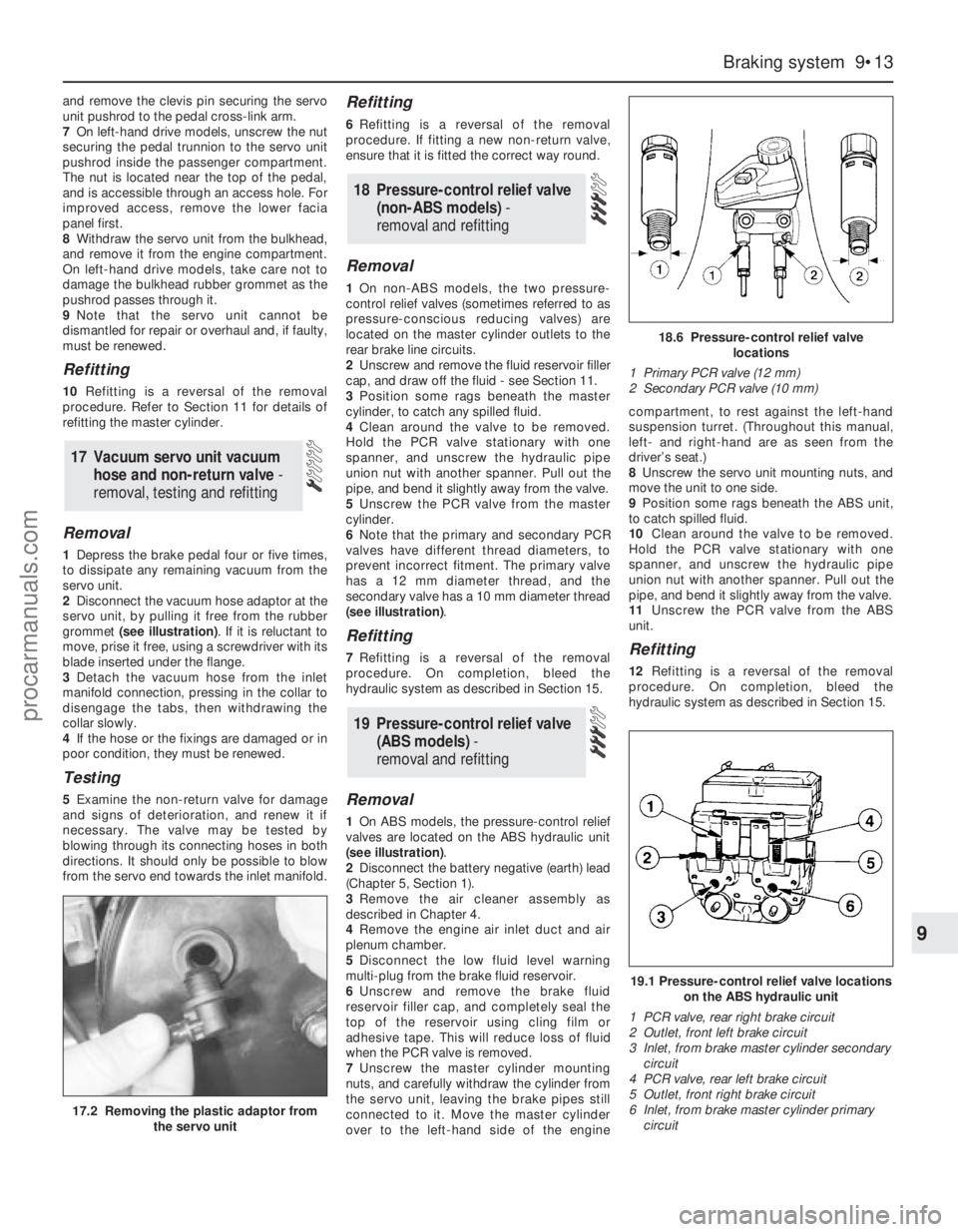
2Disconnect the vacuum hose adaptor at the
servo unit, by pulling it free from the rubber
grommet (see illustration). If it is reluctant to
move, prise it free, using a screwdriver with its
blade inserted under the flange.
3Detach the vacuum hose from the inlet
manifold connection, pressing in the collar to
disengage the tabs, then withdrawing the
collar slowly.
4If the hose or the fixings are damaged or in
poor condition, they must be renewed.
Testing
5Examine the non-return valve for damage
and signs of deterioration, and renew it if
necessary. The valve may be tested by
blowing through its connecting hoses in both
directions. It should only be possible to blow
from the servo end towards the inlet manifold.
Refitting
6Refitting is a reversal of the removal
procedure. If fitting a new non-return valve,
ensure that it is fitted the correct way round.
Removal
1On non-ABS models, the two pressure-
control relief valves (sometimes referred to as
pressure-conscious reducing valves) are
located on the master cylinder outlets to the
rear brake line circuits.
2Unscrew and remove the fluid reservoir filler
cap, and draw off the fluid - see Section 11.
3Position some rags beneath the master
cylinder, to catch any spilled fluid.
4Clean around the valve to be removed.
Hold the PCR valve stationary with one
spanner, and unscrew the hydraulic pipe
union nut with another spanner. Pull out the
pipe, and bend it slightly away from the valve.
5Unscrew the PCR valve from the master
cylinder.
6Note that the primary and secondary PCR
valves have different thread diameters, to
prevent incorrect fitment. The primary valve
has a 12 mm diameter thread, and the
secondary valve has a 10 mm diameter thread
(see illustration).
Refitting
7Refitting is a reversal of the removal
procedure. On completion, bleed the
hydraulic system as described in Section 15.
Removal
1On ABS models, the pressure-control relief
valves are located on the ABS hydraulic unit
(see illustration).
2Disconnect the battery negative (earth) lead
(Chapter 5, Section 1).
3Remove the air cleaner assembly as
described in Chapter 4.
4Remove the engine air inlet duct and air
plenum chamber.
5Disconnect the low fluid level warning
multi-plug from the brake fluid reservoir.
6Unscrew and remove the brake fluid
reservoir filler cap, and completely seal the
top of the reservoir using cling film or
adhesive tape. This will reduce loss of fluid
when the PCR valve is removed.
7Unscrew the master cylinder mounting
nuts, and carefully withdraw the cylinder from
the servo unit, leaving the brake pipes still
connected to it. Move the master cylinder
over to the left-hand side of the enginecompartment, to rest against the left-hand
suspension turret. (Throughout this manual,
left- and right-hand are as seen from the
driver’s seat.)
8Unscrew the servo unit mounting nuts, and
move the unit to one side.
9Position some rags beneath the ABS unit,
to catch spilled fluid.
10Clean around the valve to be removed.
Hold the PCR valve stationary with one
spanner, and unscrew the hydraulic pipe
union nut with another spanner. Pull out the
pipe, and bend it slightly away from the valve.
11Unscrew the PCR valve from the ABS
unit.
Refitting
12Refitting is a reversal of the removal
procedure. On completion, bleed the
hydraulic system as described in Section 15.
19 Pressure-control relief valve
(ABS models) -
removal and refitting
18 Pressure-control relief valve
(non-ABS models) -
removal and refitting
17 Vacuum servo unit vacuum
hose and non-return valve -
removal, testing and refitting
Braking system 9•13
9
17.2 Removing the plastic adaptor from
the servo unit
18.6 Pressure-control relief valve
locations
1 Primary PCR valve (12 mm)
2 Secondary PCR valve (10 mm)
19.1 Pressure-control relief valve locations
on the ABS hydraulic unit
1 PCR valve, rear right brake circuit
2 Outlet, front left brake circuit
3 Inlet, from brake master cylinder secondary
circuit
4 PCR valve, rear left brake circuit
5 Outlet, front right brake circuit
6 Inlet, from brake master cylinder primary
circuit
procarmanuals.com
Page 132 of 279
Note:If any part of the ABS hydraulic unit is
defective, it must be renewed as an assembly.
Apart from the relay box (Section 22),
individual spare parts are not available.
Removal
1Remove both pressure-control relief valves
as described in Section 19.
2Identify the location of the remaining brake
hydraulic pipes on the ABS hydraulic unit,
then unscrew the union nuts and pull out the
pipes. Carefully bend the pipes away from the
hydraulic unit, to allow the unit to be removed.
3Disconnect the multi-plugs from the
hydraulic unit. To disconnect the main 22-pin
multi-plug, push the locktab, then swivel the
multi-plug outwards and unhook it.
Right-hand drive models
4Have an assistant hold the brake pedal
depressed, then extract the spring clip and
remove the clevis pin securing the servo unit
pushrod to the pedal cross-link arm.
5Remove the vacuum servo unit from the
engine compartment.
Left-hand drive models
6Unscrew the nut securing the pedal
trunnion to the servo unit pushrod inside the
passenger compartment. The nut is located
near the top of the pedal, and is accessible
through an access hole. For improved access,
remove the lower facia panel first.
7Remove the vacuum servo unit, together
with the pushrod, from the engine
compartment. Take care not to damage the
rubber grommet in the bulkhead.
All models
8Unscrew the pump mounting nut.
9Raise the left-hand side of the ABS
hydraulic unit, then swivel the unit out of the
right-hand mounting. Take care not to lose the
bracket studs and insulator ring.
Refitting
10Locate the insulator ring on the pump
end, and fit the stud cap to the insulator ring.
11Lower the ABS hydraulic unit into
position, right-hand end first.
12Fit the right-hand bracket studs onto the
insulators.
13Lower the left-hand end of the ABS
hydraulic unit onto the bracket, then fit and
tighten the pump mounting nut.
Left-hand drive models
14Locate the vacuum servo unit and
pushrod on the bulkhead bracket, taking care
not to damage the rubber grommet.
15Insert the pushrod in the pedal trunnion,
and tighten the nut.
16Refit the lower facia panel if it was
removed.
Right-hand drive models
17Locate the vacuum servo unit and
pushrod on the bulkhead bracket.
18Refit the clevis pin and spring clip
securing the servo unit pushrod to the pedal
cross-link arm.
All models
19Reconnect the multi-plugs to the
hydraulic unit.
20Reconnect the brake pipes to the
hydraulic unit, and tighten the union nuts.
21Refit both pressure-control relief valves,
with reference to Section 20.
Testing
1Checking of the sensors is done before
removal, connecting a voltmeter to the
disconnected sensor multi-plug. Using an
analogue (moving coil) meter is not practical,
since the meter does not respond quickly
enough. A digital meter having an AC facility
may be used to check that the sensor is
operating correctly. To do this, raise the
relevant wheel then disconnect the wiring to
the ABS sensor and connect the meter to it.
Spin the wheel and check that the output
voltage is between 1.5 and 2.0 volts,
depending on how fast the wheel is spun.
Alternatively, an oscilloscope may be used to
check the output of the sensor - an alternating
current will be traced on the screen, of
magnitude depending on the speed of the
rotating wheel.
2If the sensor output is low or zero, renew
the sensor.
Removal
Front wheel sensor
3Apply the handbrake, jack up the front of
the vehicle and support it on axle stands.
Remove the relevant wheel.
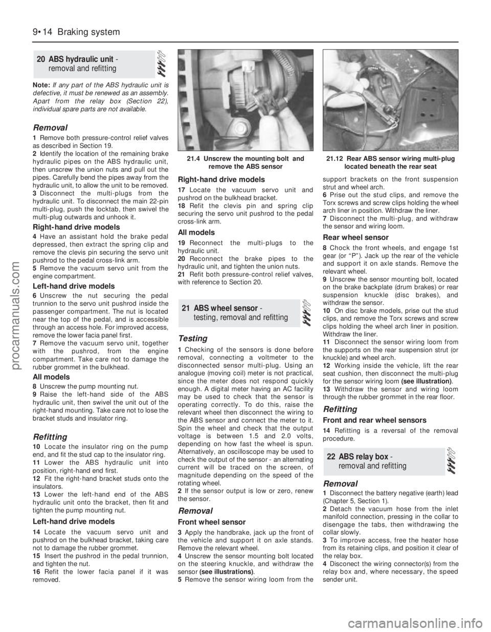
4Unscrew the sensor mounting bolt located
on the steering knuckle, and withdraw the
sensor (see illustrations).
5Remove the sensor wiring loom from thesupport brackets on the front suspension
strut and wheel arch.
6Prise out the stud clips, and remove the
Torx screws and screw clips holding the wheel
arch liner in position. Withdraw the liner.
7Disconnect the multi-plug, and withdraw
the sensor and wiring loom.
Rear wheel sensor
8Chock the front wheels, and engage 1st
gear (or “P”). Jack up the rear of the vehicle
and support it on axle stands. Remove the
relevant wheel.
9Unscrew the sensor mounting bolt, located
on the brake backplate (drum brakes) or rear
suspension knuckle (disc brakes), and
withdraw the sensor.
10On disc brake models, prise out the stud
clips, and remove the Torx screws and screw
clips holding the wheel arch liner in position.
Withdraw the liner.
11Disconnect the sensor wiring loom from
the supports on the rear suspension strut (or
knuckle) and wheel arch.
12Working inside the vehicle, lift the rear
seat cushion, then disconnect the multi-plug
for the sensor wiring loom (see illustration).
13Withdraw the sensor and wiring loom
through the rubber grommet in the rear floor.
Refitting
Front and rear wheel sensors
14Refitting is a reversal of the removal
procedure.
Removal
1Disconnect the battery negative (earth) lead
(Chapter 5, Section 1).
2Detach the vacuum hose from the inlet
manifold connection, pressing in the collar to
disengage the tabs, then withdrawing the
collar slowly.
3To improve access, free the heater hose
from its retaining clips, and position it clear of
the relay box.
4Disconect the wiring connector(s) from the
relay box and, where necessary, the speed
sender unit.
22 ABS relay box -
removal and refitting
21 ABS wheel sensor -
testing, removal and refitting
20 ABS hydraulic unit -
removal and refitting
9•14 Braking system
21.4 Unscrew the mounting bolt and
remove the ABS sensor21.12 Rear ABS sensor wiring multi-plug
located beneath the rear seat
procarmanuals.com