1993 FORD MONDEO battery location
[x] Cancel search: battery locationPage 137 of 279
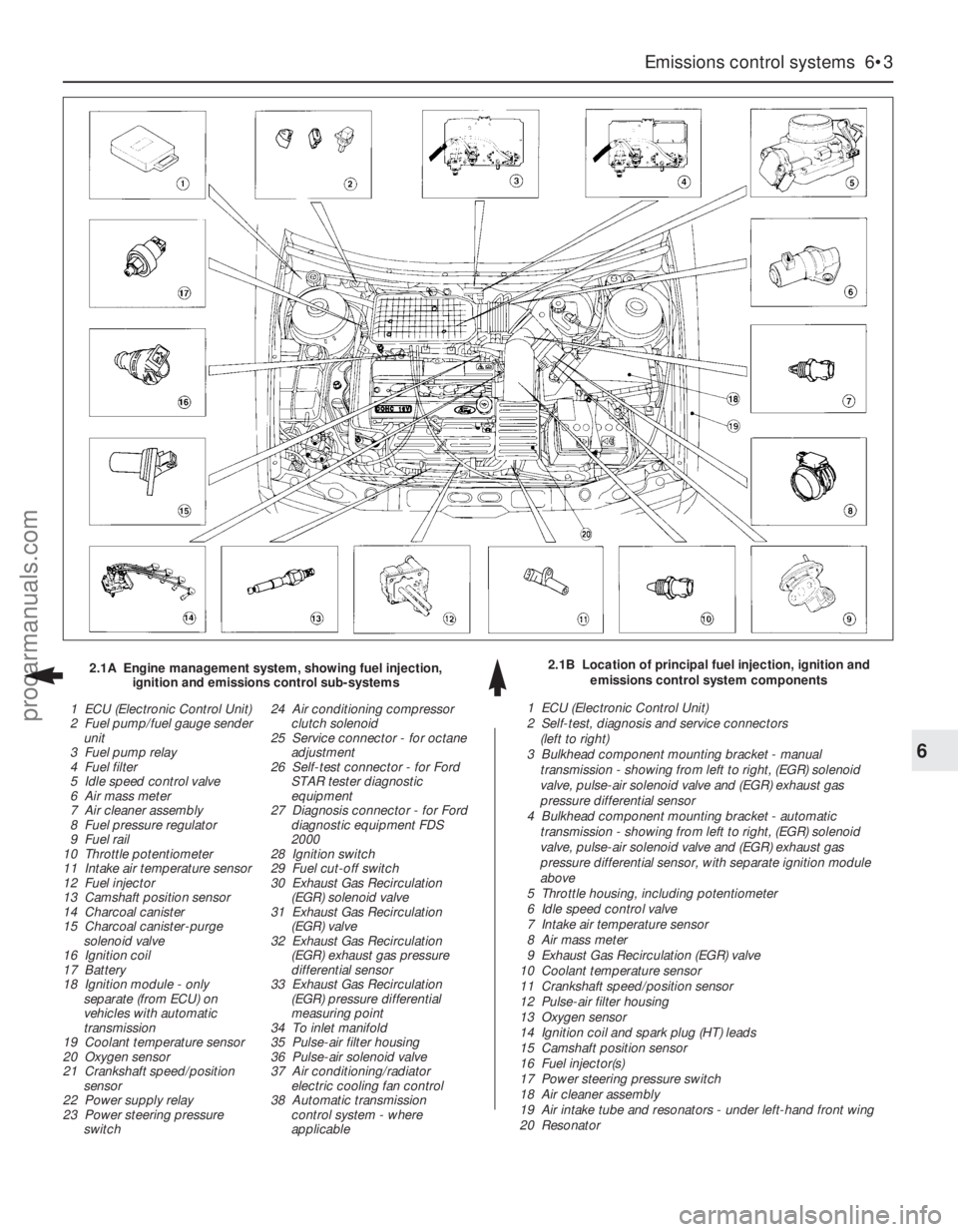
Emissions control systems 6•3
6
2.1B Location of principal fuel injection, ignition and
emissions control system components 2.1A Engine management system, showing fuel injection,
ignition and emissions control sub-systems
1 ECU (Electronic Control Unit)
2 Fuel pump/fuel gauge sender
unit
3 Fuel pump relay
4 Fuel filter
5 Idle speed control valve
6 Air mass meter
7 Air cleaner assembly
8 Fuel pressure regulator
9 Fuel rail
10 Throttle potentiometer
11 Intake air temperature sensor
12 Fuel injector
13 Camshaft position sensor
14 Charcoal canister
15 Charcoal canister-purge
solenoid valve
16 Ignition coil
17 Battery
18 Ignition module - only
separate (from ECU) on
vehicles with automatic
transmission
19 Coolant temperature sensor
20 Oxygen sensor
21 Crankshaft speed/position
sensor
22 Power supply relay
23 Power steering pressure
switch24 Air conditioning compressor
clutch solenoid
25 Service connector - for octane
adjustment
26 Self-test connector - for Ford
STAR tester diagnostic
equipment
27 Diagnosis connector - for Ford
diagnostic equipment FDS
2000
28 Ignition switch
29 Fuel cut-off switch
30 Exhaust Gas Recirculation
(EGR) solenoid valve
31 Exhaust Gas Recirculation
(EGR) valve
32 Exhaust Gas Recirculation
(EGR) exhaust gas pressure
differential sensor
33 Exhaust Gas Recirculation
(EGR) pressure differential
measuring point
34 To inlet manifold
35 Pulse-air filter housing
36 Pulse-air solenoid valve
37 Air conditioning/radiator
electric cooling fan control
38 Automatic transmission
control system - where
applicable1 ECU (Electronic Control Unit)
2 Self-test, diagnosis and service connectors
(left to right)
3 Bulkhead component mounting bracket - manual
transmission - showing from left to right, (EGR) solenoid
valve, pulse-air solenoid valve and (EGR) exhaust gas
pressure differential sensor
4 Bulkhead component mounting bracket - automatic
transmission - showing from left to right, (EGR) solenoid
valve, pulse-air solenoid valve and (EGR) exhaust gas
pressure differential sensor, with separate ignition module
above
5 Throttle housing, including potentiometer
6 Idle speed control valve
7 Intake air temperature sensor
8 Air mass meter
9 Exhaust Gas Recirculation (EGR) valve
10 Coolant temperature sensor
11 Crankshaft speed/position sensor
12 Pulse-air filter housing
13 Oxygen sensor
14 Ignition coil and spark plug (HT) leads
15 Camshaft position sensor
16 Fuel injector(s)
17 Power steering pressure switch
18 Air cleaner assembly
19 Air intake tube and resonators - under left-hand front wing
20 Resonator
procarmanuals.com
Page 138 of 279
constantly monitors the oxygen content of the
exhaust gas. If the percentage of oxygen in
the exhaust gas is incorrect, an electrical
signal is sent to the ECU. The ECU processes
this information, and then sends a command
to the fuel injection system, telling it to change
the air/fuel mixture; the end result is an air/fuel
mixture ratio which is constantly maintained
at a predetermined ratio, regardless of driving
conditions. This happens in a fraction of a
second, and goes on almost all the time while
the engine is running - the exceptions are that
the ECU cuts out the system and runs the
engine on values pre-programmed
(“mapped”) into its memory both while the
oxygen sensor is reaching its normal
operating temperature after the engine has
been started from cold, and when the throttle
is fully open for full acceleration.
In the event of a sensor malfunction, a
back-up circuit will take over, to provide
driveability until the problem is identified and
fixed.
Precautions
(a) Always disconnect the power by
uncoupling the battery terminals - see
Section 1 of Chapter 5 - before removing
any of the electronic control system’s
electrical connectors.
(b) When installing a battery, be particularly
careful to avoid reversing the positive and
negative battery leads.
(c) Do not subject any components of the
system (especially the ECU) to severe
impact during removal or installation.
(d) Do not be careless during fault diagnosis.
Even slight terminal contact can invalidate
a testing procedure, and damage one of
the numerous transistor circuits.
(e) Never attempt to work on the ECU, to test
it (with any kind of test equipment), or to
open its cover.
(f) If you are inspecting electronic control
system components during rainy weather,
make sure that water does not enter any
part. When washing the engine
compartment, do not spray these parts or
their electrical connectors with water.
General
The various components of the fuel, ignition
and emissions control systems (not forgetting
the same ECU’s control of sub-systems such
as the radiator cooling fan, air conditioning
and automatic transmission, where
appropriate) are so closely interlinked that
diagnosis of a fault in any one component is
virtually impossible using traditional methods.
Working on simpler systems in the past, the
experienced mechanic may well have been
able to use personal skill and knowledge
immediately to pinpoint the cause of a fault, or
quickly to isolate the fault, by elimination;however, with an engine management system
integrated to this degree, this is not likely to
be possible in most instances, because of the
number of symptoms that could arise from
even a minor fault.
So that the causes of faults can be quickly
and accurately traced and rectified, the ECU
is provided with a built-in self-diagnosis
facility, which detects malfunctions in the
system’s components. When a fault occurs,
three things happen: the ECU identifies the
fault, stores a corresponding code in its
memory, and (in most cases) runs the system
using back-up values pre-programmed
(“mapped”) into its memory; some form of
driveability is thus maintained, to enable the
vehicle to be driven to a garage for attention.
Any faults that may have occurred are
indicated in the form of three-digit codes
when the system is connected (via the built-in
diagnosis or self-test connectors, as
appropriate) to special diagnostic equipment -
this points the user in the direction of the
faulty circuit, so that further tests can pinpoint
the exact location of the fault.
Given below is the procedure that would be
followed by a Ford technician to trace a fault
from scratch. Should your vehicle’s engine
management system develop a fault, read
through the procedure and decide how much
you can attempt, depending on your skill and
experience and the equipment available to
you, or whether it would be simpler to have
the vehicle attended to by your local Ford
dealer. If you are concerned about the
apparent complexity of the system, however,
remember the comments made in the fourth
paragraph of Section 1 of this Chapter; the
preliminary checks require nothing but care,
patience and a few minor items of equipment,
and may well eliminate the majority of faults.
(a) Preliminary checks
(b) Fault code read-out *
(c) Check ignition timing and base idle
speed. Recheck fault codes to establish
whether fault has been cured or not *
(d) Carry out basic check of ignition system
components. Recheck fault codes to
establish whether fault has been cured or
not *
(e) Carry out basic check of fuel system
components. Recheck fault codes to
establish whether fault has been cured or
not *
(f) If fault is still not located, carry out system
test *
Note:Operations marked with an asterisk
require special test equipment.
Preliminary checks
Note:When carrying out these checks to
trace a fault, remember that if the fault has
appeared only a short time after any part of
the vehicle has been serviced or overhauled,
the first place to check is where that work was
carried out, however unrelated it may appear,
to ensure that no carelessly-refitted
components are causing the problem.If you are tracing the cause of a “partial”
engine fault, such as lack of performance, in
addition to the checks outlined below, check
the compression pressures (see Part A of
Chapter 2) and bear in mind the possibility
that one of the hydraulic tappets might be
faulty, producing an incorrect valve clearance.
Check also that the fuel filter has been
renewed at the recommended intervals.
If the system appears completely dead,
remember the possibility that the
alarm/inhibitor system may be responsible.
1The first check for anyone without special
test equipment is to switch on the ignition,
and to listen for the fuel pump (the sound of
an electric motor running, audible from
beneath the rear seats); assuming there is
sufficient fuel in the tank, the pump should
start and run for approximately one or two
seconds, then stop, each time the ignition is
switched on. If the pump runs continuously all
the time the ignition is switched on, the
electronic control system is running in the
back-up (or “limp-home”) mode referred to by
Ford as “Limited Operation Strategy” (LOS).
This almost certainly indicates a fault in the
ECU itself, and the vehicle should therefore be
taken to a Ford dealer for a full test of the
complete system using the correct diagnostic
equipment; do not waste time trying to test
the system without such facilities.
2If the fuel pump is working correctly (or not
at all), a considerable amount of fault
diagnosis is still possible without special test
equipment. Start the checking procedure as
follows.
3Open the bonnet and check the condition
of the battery connections - remake the
connections or renew the leads if a fault is
found (Chapter 5). Use the same techniques
to ensure that all earth points in the engine
compartment provide good electrical contact
through clean, metal-to-metal joints, and that
all are securely fastened. (In addition to the
earth connection at the engine lifting eye and
that from the transmission to the
body/battery, there is one earth connection
behind each headlight assembly, and one
below the power steering fluid reservoir.)
4Referring to the information given in
Chapter 12 and in the wiring diagrams at the
back of this manual, check that all fuses
protecting the circuits related to the engine
management system are in good condition.
Fit new fuses if required; while you are there,
check that all relays are securely plugged into
their sockets.
5Next work methodically around the engine
compartment, checking all visible wiring, and
the connections between sections of the
wiring loom. What you are looking for at this
stage is wiring that is obviously damaged by
chafing against sharp edges, or against
moving suspension/transmission components
and/or the auxiliary drivebelt, by being
trapped or crushed between carelessly-
refitted components, or melted by being
forced into contact with hot engine castings,
3 Diagnosis system -
general information
6•4 Emissions control systems
procarmanuals.com
Page 174 of 279
15Locate the steering column shaft on the
flexible coupling, swivel the clamp plate
round, then insert the bolt and tighten to the
specified torque.
16Refit the driver’s side lower trim panel.
17Refit the steering column upper and lower
shrouds.
18Reconnect the battery negative lead.
Removal
1Disconnect the battery negative (earth) lead
(refer to Chapter 5, Section 1).
2Turn the steering wheel so that the front
wheels are in the straight-ahead position.
Remove the ignition key, then turn the
steering wheel slightly as necessary until the
steering lock engages.
3Unscrew the clamp plate bolt securing the
steering column shaft to the flexible coupling.
Swivel the clamp plate around, and disengage
it from the flexible coupling stub.
4Carefully prise the rubber boot from the
bulkhead, and withdraw it into the passenger
compartment. Take care not to damage the
sealing lip of the boot.
5Using an Allen key, unscrew the clamp bolt
securing the flexible coupling to the pinion
shaft on the steering gear, and withdraw the
coupling from inside the vehicle.
Refitting
6Refitting is a reversal of the removal
procedure, but tighten the clamp bolts to the
specified torque. Make sure that the rubber
boot engages correctly in the bulkhead and
on the flexible coupling.
Removal
1Remove the steering column flexible
coupling as described in Section 29.
2Apply the handbrake, then jack up the frontof the vehicle and support it on axle stands.
Remove both front wheels.
3Working beneath the vehicle, unbolt the
rear engine mounting from the transmission
and underbody.
4Extract the split pins from the track rod end
balljoint nuts, then unscrew the nuts, and
detach the rods from the arms on the steering
knuckles using a conventional balljoint
removal tool. Take care not to damage the
balljoint seals.
5Position a suitable container beneath the
steering gear, then unscrew the union nuts
securing the power steering fluid supply,
return, and cooler lines to the steering gear.
Identify the lines for position, then unbolt the
clamps, disconnect the lines, and allow the
fluid to drain into the container. Cover the
apertures in the steering gear and also the
ends of the fluid pipes, to prevent the ingress
of dust and dirt into the hydraulic circuit.
6Unscrew and remove the steering gear
mounting bolts. The bolts are located on top
of the steering gear, and are difficult to reach.
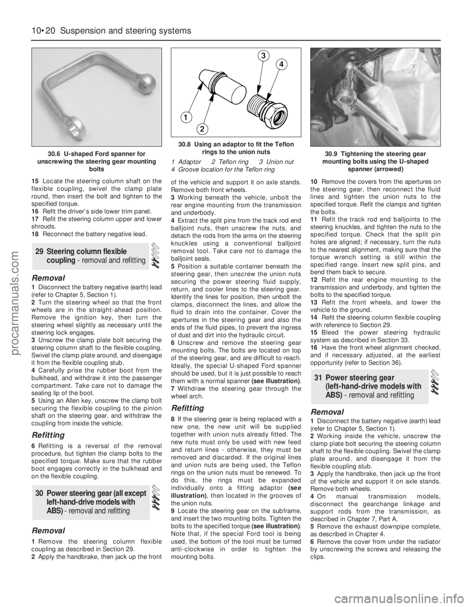
Ideally, the special U-shaped Ford spanner
should be used, but it is just possible to reach
them with a normal spanner (see illustration).
7Withdraw the steering gear through the
wheel arch.
Refitting
8If the steering gear is being replaced with a
new one, the new unit will be supplied
together with union nuts already fitted. The
new nuts must only be used with new feed
and return lines - otherwise, they must be
removed and discarded. If the original lines
and union nuts are being used, the Teflon
rings on the union nuts must be renewed. To
do this, the rings must be expanded
individually onto a fitting adaptor (see
illustration), then located in the grooves of
the union nuts.
9Locate the steering gear on the subframe,
and insert the two mounting bolts. Tighten the
bolts to the specified torque (see illustration).
Note that, if the special Ford tool is being
used, the bottom of the tool must be turned
anti-clockwise in order to tighten the
mounting bolts.10Remove the covers from the apertures on
the steering gear, then reconnect the fluid
lines and tighten the union nuts to the
specified torque. Refit the clamps and tighten
the bolts.
11Refit the track rod end balljoints to the
steering knuckles, and tighten the nuts to the
specified torque. Check that the split pin
holes are aligned; if necessary, turn the nuts
to the nearest alignment, making sure that the
torque wrench setting is still within the
specified range. Insert new split pins, and
bend them back to secure.
12Refit the rear engine mounting to the
transmission and underbody, and tighten the
bolts to the specified torque.
13Refit the front wheels, and lower the
vehicle to the ground.
14Refit the steering column flexible coupling
with reference to Section 29.
15Bleed the power steering hydraulic
system as described in Section 33.
16Have the front wheel alignment checked,
and if necessary adjusted, at the earliest
opportunity (refer to Section 36).Removal
1Disconnect the battery negative (earth) lead
(refer to Chapter 5, Section 1).
2Working inside the vehicle, unscrew the
clamp plate bolt securing the steering column
shaft to the flexible coupling. Swivel the clamp
plate around, and disengage it from the
flexible coupling stub.
3Apply the handbrake, then jack up the front
of the vehicle and support it on axle stands.
Remove both wheels.
4On manual transmission models,
disconnect the gearchange linkage and
support rods from the transmission, as
described in Chapter 7, Part A.
5Remove the exhaust downpipe complete,
as described in Chapter 4.
6Remove the cover from under the radiator
by unscrewing the screws and releasing the
clips.
31 Power steering gear
(left-hand-drive models with
ABS) - removal and refitting
30 Power steering gear (all except
left-hand-drive models with
ABS) - removal and refitting
29 Steering column flexible
coupling - removal and refitting
10•20 Suspension and steering systems
30.6 U-shaped Ford spanner for
unscrewing the steering gear mounting
bolts
30.8 Using an adaptor to fit the Teflon
rings to the union nuts
1 Adaptor 2 Teflon ring 3 Union nut
4 Groove location for the Teflon ring
30.9 Tightening the steering gear
mounting bolts using the U-shaped
spanner (arrowed)
procarmanuals.com
Page 179 of 279
models (see illustration). In other countries, it
is available on certain models only. Where
double-locking is fitted, the lock mechanism
is disconnected (when the system is in use)
from the interior door handles, making it
impossible to open any of the doors or the
tailgate/bootlid from inside the vehicle. This
means that, even if a thief should break a side
window, he will not be able to open the door
using the interior handle. Models with the
double-locking system are fitted with a
control module located beneath the facia on
the right-hand side. In the event of a serious
accident, a crash sensor unlocks all doors if
they were previously locked.
Many of the procedures in this Chapter
require the battery to be disconnected. Refer
to Chapter 5, Section 1 first.
The general condition of a vehicle’s
bodywork is the one thing that significantly
affects its value. Maintenance is easy, but
needs to be regular. Neglect, particularly after
minor damage, can lead quickly to further
deterioration and costly repair bills. It is
important also to keep watch on those parts
of the vehicle not immediately visible, for
instance the underside, inside all the wheel
arches, and the lower part of the engine
compartment.
The basic maintenance routine for the
bodywork is washing - preferably with a lot of
water, from a hose. This will remove all the
loose solids which may have stuck to the
vehicle. It is important to flush these off in
such a way as to prevent grit from scratching
the finish. The wheel arches and underframe
need washing in the same way, to remove any
accumulated mud, which will retain moisture
and tend to encourage rust. Paradoxically
enough, the best time to clean the underframe
and wheel arches is in wet weather, when the
mud is thoroughly wet and soft. In very wet
weather, the underframe is usually cleaned of
large accumulations automatically, and this is
a good time for inspection.
Periodically, except on vehicles with a wax-
based underbody protective coating, it is a
good idea to have the whole of the
underframe of the vehicle steam-cleaned,
engine compartment included, so that a
thorough inspection can be carried out to see
what minor repairs and renovations are
necessary. Steam-cleaning is available at
many garages, and is necessary for the
removal of the accumulation of oily grime,
which sometimes is allowed to become thick
in certain areas. If steam-cleaning facilities are
not available, there are some excellent grease
solvents available which can be brush-
applied; the dirt can then be simply hosed off.
Note that these methods should not be used
on vehicles with wax-based underbodyprotective coating, or the coating will be
removed. Such vehicles should be inspected
annually, preferably just prior to Winter, when
the underbody should be washed down, and
any damage to the wax coating repaired.
Ideally, a completely fresh coat should be
applied. It would also be worth considering
the use of such wax-based protection for
injection into door panels, sills, box sections,
etc, as an additional safeguard against rust
damage, where such protection is not
provided by the vehicle manufacturer.
After washing paintwork, wipe off with a
chamois leather to give an unspotted clear
finish. A coat of clear protective wax polish
will give added protection against chemical
pollutants in the air. If the paintwork sheenhas dulled or oxidised, use a cleaner/polisher
combination to restore the brilliance of the
shine. This requires a little effort, but such
dulling is usually caused because regular
washing has been neglected. Care needs to
be taken with metallic paintwork, as special
non-abrasive cleaner/polisher is required to
avoid damage to the finish. Always check that
the door and ventilator opening drain holes
and pipes are completely clear, so that water
can be drained out. Brightwork should be
treated in the same way as paintwork.
Windscreens and windows can be kept clear
of the smeary film which often appears, by the
use of proprietary glass cleaner. Never use
any form of wax or other body or chromium
polish on glass.
2 Maintenance -
bodywork and underframe
11•2 Bodywork and fittings
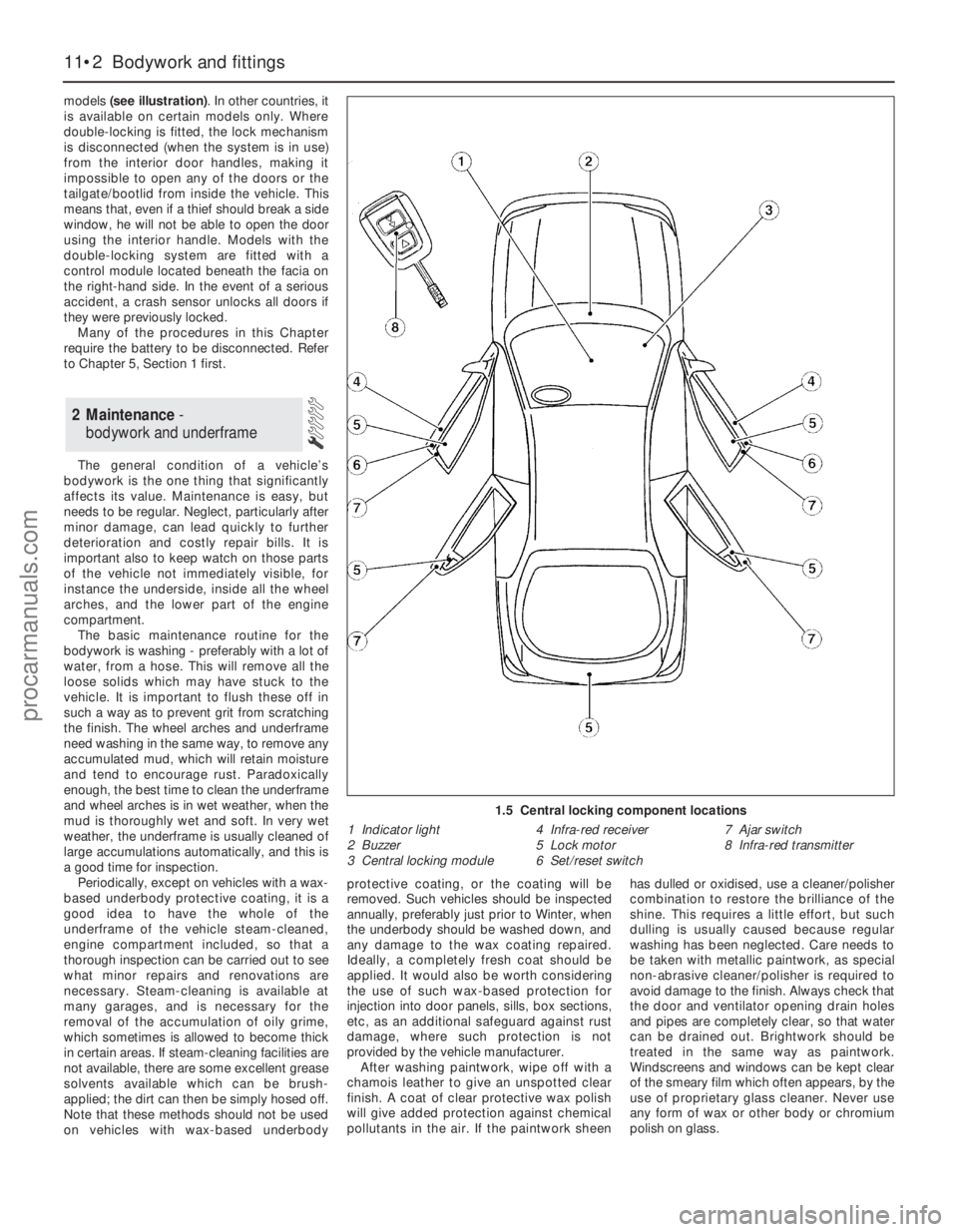
1.5 Central locking component locations
1 Indicator light
2 Buzzer
3 Central locking module4 Infra-red receiver
5 Lock motor
6 Set/reset switch7 Ajar switch
8 Infra-red transmitter
procarmanuals.com
Page 195 of 279
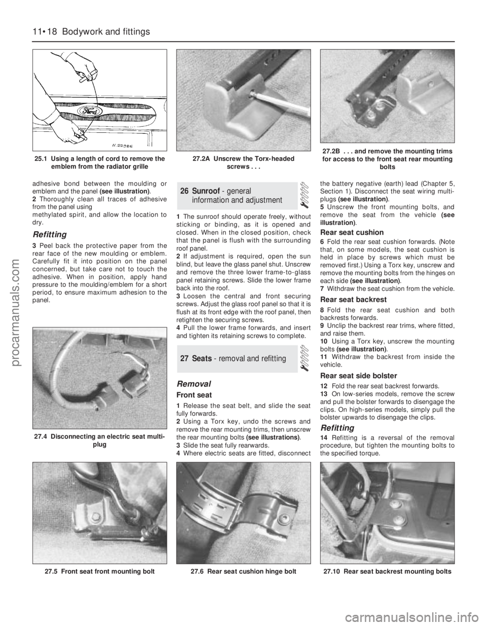
adhesive bond between the moulding or
emblem and the panel (see illustration).
2Thoroughly clean all traces of adhesive
from the panel using
methylated spirit, and allow the location to
dry.
Refitting
3Peel back the protective paper from the
rear face of the new moulding or emblem.
Carefully fit it into position on the panel
concerned, but take care not to touch the
adhesive. When in position, apply hand
pressure to the moulding/emblem for a short
period, to ensure maximum adhesion to the
panel.1The sunroof should operate freely, without
sticking or binding, as it is opened and
closed. When in the closed position, check
that the panel is flush with the surrounding
roof panel.
2If adjustment is required, open the sun
blind, but leave the glass panel shut. Unscrew
and remove the three lower frame-to-glass
panel retaining screws. Slide the lower frame
back into the roof.
3Loosen the central and front securing
screws. Adjust the glass roof panel so that it is
flush at its front edge with the roof panel, then
retighten the securing screws.
4Pull the lower frame forwards, and insert
and tighten its retaining screws to complete.
Removal
Front seat
1Release the seat belt, and slide the seat
fully forwards.
2Using a Torx key, undo the screws and
remove the rear mounting trims, then unscrew
the rear mounting bolts (see illustrations).
3Slide the seat fully rearwards.
4Where electric seats are fitted, disconnectthe battery negative (earth) lead (Chapter 5,
Section 1). Disconnect the seat wiring multi-
plugs (see illustration).
5Unscrew the front mounting bolts, and
remove the seat from the vehicle (see
illustration).
Rear seat cushion
6Fold the rear seat cushion forwards. (Note
that, on some models, the seat cushion is
held in place by screws which must be
removed first.) Using a Torx key, unscrew and
remove the mounting bolts from the hinges on
each side (see illustration).
7Withdraw the seat cushion from the vehicle.
Rear seat backrest
8Fold the rear seat cushion and both
backrests forwards.
9Unclip the backrest rear trims, where fitted,
and raise them.
10Using a Torx key, unscrew the mounting
bolts (see illustration).
11Withdraw the backrest from inside the
vehicle.
Rear seat side bolster
12Fold the rear seat backrest forwards.
13On low-series models, remove the screw
and pull the bolster forwards to disengage the
clips. On high-series models, simply pull the
bolster upwards to disengage the clips.
Refitting
14Refitting is a reversal of the removal
procedure, but tighten the mounting bolts to
the specified torque.
27 Seats - removal and refitting
26 Sunroof - general
information and adjustment
11•18 Bodywork and fittings
25.1 Using a length of cord to remove the
emblem from the radiator grille27.2A Unscrew the Torx-headed
screws . . .27.2B . . . and remove the mounting trims
for access to the front seat rear mounting
bolts
27.5 Front seat front mounting bolt
27.4 Disconnecting an electric seat multi-
plug
27.6 Rear seat cushion hinge bolt27.10 Rear seat backrest mounting bolts
procarmanuals.com
Page 198 of 279
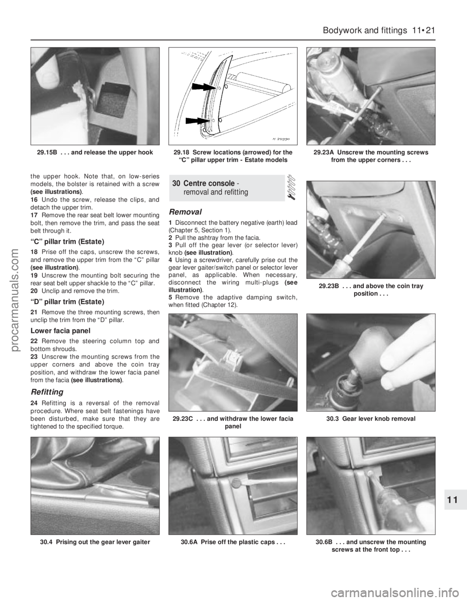
the upper hook. Note that, on low-series
models, the bolster is retained with a screw
(see illustrations).
16Undo the screw, release the clips, and
detach the upper trim.
17Remove the rear seat belt lower mounting
bolt, then remove the trim, and pass the seat
belt through it.
“C” pillar trim (Estate)
18Prise off the caps, unscrew the screws,
and remove the upper trim from the “C” pillar
(see illustration).
19Unscrew the mounting bolt securing the
rear seat belt upper shackle to the “C” pillar.
20Unclip and remove the trim.
“D” pillar trim (Estate)
21Remove the three mounting screws, then
unclip the trim from the “D” pillar.
Lower facia panel
22Remove the steering column top and
bottom shrouds.
23Unscrew the mounting screws from the
upper corners and above the coin tray
position, and withdraw the lower facia panel
from the facia (see illustrations).
Refitting
24Refitting is a reversal of the removal
procedure. Where seat belt fastenings have
been disturbed, make sure that they are
tightened to the specified torque.
Removal
1Disconnect the battery negative (earth) lead
(Chapter 5, Section 1).
2Pull the ashtray from the facia.
3Pull off the gear lever (or selector lever)
knob (see illustration).
4Using a screwdriver, carefully prise out the
gear lever gaiter/switch panel or selector lever
panel, as applicable. When necessary,
disconnect the wiring multi-plugs (see
illustration).
5Remove the adaptive damping switch,
when fitted (Chapter 12).
30 Centre console-
removal and refitting
Bodywork and fittings 11•21
11
30.4 Prising out the gear lever gaiter30.6A Prise off the plastic caps . . .30.6B . . . and unscrew the mounting
screws at the front top . . .
29.23B . . . and above the coin tray
position . . .
29.23C . . . and withdraw the lower facia
panel30.3 Gear lever knob removal
29.15B . . . and release the upper hook29.18 Screw locations (arrowed) for the
“C” pillar upper trim - Estate models29.23A Unscrew the mounting screws
from the upper corners . . .
procarmanuals.com
Page 200 of 279
Removal
1Disconnect the battery negative (earth) lead
(Chapter 5, Section 1).
2Remove the windscreen wiper arms
(Chapter 12), then remove the cowl from just
in front of the windscreen. The cowl is in two
sections, with retaining screws located along
its front edge. With the cowl removed,
disconnect the speedometer cable by pulling
it from the intermediate inner cable extension.
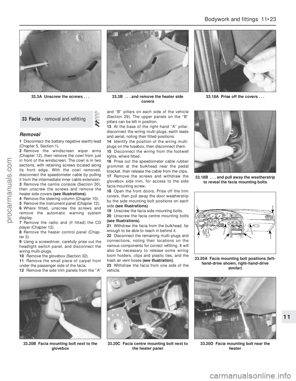
3Remove the centre console (Section 30),
then unscrew the screws and remove the
heater side covers (see illustrations).
4Remove the steering column (Chapter 10).
5Remove the instrument panel (Chapter 12).
6Where fitted, unscrew the screws and
remove the automatic warning system
display.
7Remove the radio and (if fitted) the CD
player (Chapter 12).
8Remove the heater control panel (Chap-
ter 3).
9Using a screwdriver, carefully prise out the
headlight switch panel, and disconnect the
wiring multi-plugs.
10Remove the glovebox (Section 32).
11Remove the small piece of carpet from
under the passenger side of the facia.
12Remove the side trim panels from the “A”and “B” pillars on each side of the vehicle
(Section 29). The upper panels on the “B”
pillars can be left in position.
13At the base of the right-hand “A” pillar,
disconnect the wiring multi-plugs, earth leads
and aerial, noting their fitted positions.
14Identify the position of the wiring multi-
plugs on the fusebox, then disconnect them.
15Disconnect the wiring from the footwell
lights, where fitted.
16Prise out the speedometer cable rubber
grommet at the bulkhead near the pedal
bracket, then release the cable from the clips.
17Remove the screws and withdraw the
glovebox side trim, for access to the side
facia mounting screw.
18Open the front doors. Prise off the trim
covers, then pull away the door weatherstrip
by the side mounting bolt positions on each
side (see illustrations).
19Unscrew the facia side mounting bolts.
20Unscrew the facia centre mounting bolts
(see illustrations).
21Withdraw the facia from the bulkhead, far
enough to be able to reach in behind it.
22Disconnect the remaining multi-plugs and
connections, noting their locations on the
various components for correct refitting. It will
also be necessary to release some wiring
loom holders, clips and plastic ties, and the
fresh air vent hoses (see illustration).
23Withdraw the facia from one side of the
vehicle.
33 Facia - removal and refitting
Bodywork and fittings 11•23
11
33.20B Facia mounting bolt next to the
glovebox33.20C Facia centre mounting bolt next to
the heater panel33.20D Facia mounting bolt near the
heater
33.3A Unscrew the screws . . .33.3B . . . and remove the heater side
covers33.18A Prise off the covers . . .
33.18B . . . and pull away the weatherstrip
to reveal the facia mounting bolts
33.20A Facia mounting bolt positions (left-
hand-drive shown, right-hand-drive
similar)
procarmanuals.com
Page 203 of 279
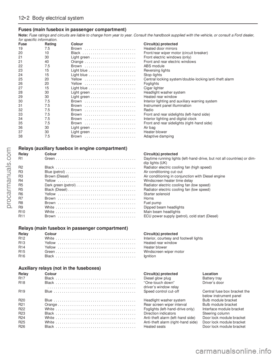
Fuses (main fusebox in passenger compartment)
Note:Fuse ratings and circuits are liable to change from year to year. Consult the handbook supplied with the vehicle, or consult a Ford dealer,
for specific information.
Fuse Rating Colour Circuit(s) protected
19 7.5 Brown . . . . . . . . . . . . . . . . . . . . . . . . . Heated door mirrors
20 10 Black . . . . . . . . . . . . . . . . . . . . . . . . . . Front/rear wiper motor (circuit breaker)
21 30 Light green . . . . . . . . . . . . . . . . . . . . . . Front electric windows (only)
21 40 Orange . . . . . . . . . . . . . . . . . . . . . . . . . Front and rear electric windows
22 7.5 Brown . . . . . . . . . . . . . . . . . . . . . . . . . ABS module
23 15 Light blue . . . . . . . . . . . . . . . . . . . . . . . Reversing lights
24 15 Light blue . . . . . . . . . . . . . . . . . . . . . . . Stop-lights
25 20 Yellow . . . . . . . . . . . . . . . . . . . . . . . . . Central locking system/double-locking/anti-theft alarm
26 20 Yellow . . . . . . . . . . . . . . . . . . . . . . . . . Foglights
27 15 Light blue . . . . . . . . . . . . . . . . . . . . . . . Cigar lighter
28 30 Light green . . . . . . . . . . . . . . . . . . . . . . Headlight washer system
29 30 Light green . . . . . . . . . . . . . . . . . . . . . . Heated rear window
30 7.5 Brown . . . . . . . . . . . . . . . . . . . . . . . . . Interior lighting and auxiliary warning system
31 7.5 Brown . . . . . . . . . . . . . . . . . . . . . . . . . Instrument panel illumination
32 7.5 Brown . . . . . . . . . . . . . . . . . . . . . . . . . Radio
33 7.5 Brown . . . . . . . . . . . . . . . . . . . . . . . . . Front and rear sidelights (left-hand side)
34 7.5 Brown . . . . . . . . . . . . . . . . . . . . . . . . . Interior lighting and digital clock
35 7.5 Brown . . . . . . . . . . . . . . . . . . . . . . . . . Front and rear sidelights (right-hand side)
36 30 Light green . . . . . . . . . . . . . . . . . . . . . . Air bag
37 30 Light green . . . . . . . . . . . . . . . . . . . . . . Heater blower
38 7.5 Brown . . . . . . . . . . . . . . . . . . . . . . . . . Adaptive damping
Relays (auxiliary fusebox in engine compartment)
Relay Colour Circuit(s) protected
R1 Green . . . . . . . . . . . . . . . . . . . . . . . . . . . . . . . . . . . . . . . Daytime running lights (left-hand-drive, but not all countries) or dim-
dip lights (UK)
R2 Black . . . . . . . . . . . . . . . . . . . . . . . . . . . . . . . . . . . . . . . Radiator electric cooling fan (high speed)
R3 Blue (petrol) . . . . . . . . . . . . . . . . . . . . . . . . . . . . . . . . . . Air conditioning cut-out
R3 Brown (Diesel) . . . . . . . . . . . . . . . . . . . . . . . . . . . . . . . . Air conditioning in conjunction with Diesel engine
R4 Yellow . . . . . . . . . . . . . . . . . . . . . . . . . . . . . . . . . . . . . . Windscreen heater time delay
R5 Dark green (petrol) . . . . . . . . . . . . . . . . . . . . . . . . . . . . . Radiator electric cooling fan (low speed)
R5 Black (Diesel) . . . . . . . . . . . . . . . . . . . . . . . . . . . . . . . . . Radiator electric cooling fan (low speed)
R6 Yellow . . . . . . . . . . . . . . . . . . . . . . . . . . . . . . . . . . . . . . Starter solenoid
R7 Brown . . . . . . . . . . . . . . . . . . . . . . . . . . . . . . . . . . . . . . Horns
R8 Brown . . . . . . . . . . . . . . . . . . . . . . . . . . . . . . . . . . . . . . Fuel pump
R9 White . . . . . . . . . . . . . . . . . . . . . . . . . . . . . . . . . . . . . . . Dipped beam headlights
R10 White . . . . . . . . . . . . . . . . . . . . . . . . . . . . . . . . . . . . . . . Main beam headlights
R11 Brown . . . . . . . . . . . . . . . . . . . . . . . . . . . . . . . . . . . . . . ECU power supply (petrol), cold start (Diesel)
Relays (main fusebox in passenger compartment)
Relay Colour Circuit(s) protected
R12 White . . . . . . . . . . . . . . . . . . . . . . . . . . . . . . . . . . . . . . . Interior, courtesy and footwell lights
R13 Yellow . . . . . . . . . . . . . . . . . . . . . . . . . . . . . . . . . . . . . . Heated rear window
R14 Yellow . . . . . . . . . . . . . . . . . . . . . . . . . . . . . . . . . . . . . . Heater blower
R15 Green . . . . . . . . . . . . . . . . . . . . . . . . . . . . . . . . . . . . . . . Windscreen wiper motor
R16 Black . . . . . . . . . . . . . . . . . . . . . . . . . . . . . . . . . . . . . . . Ignition
Auxiliary relays (not in the fuseboxes)
Relay Colour Circuit(s) protected Location
R17 Black . . . . . . . . . . . . . . . . . . . . . . . . . . . . . . . . . . . . . . . Diesel glow plug Battery tray
R18 Black . . . . . . . . . . . . . . . . . . . . . . . . . . . . . . . . . . . . . . . “One-touch down” Driver’s door
. . . . . . . . . . . . . . . . . . . . . . . . . . . . . . . . . . . . . . . . . . . driver’s window relay
R19 Blue . . . . . . . . . . . . . . . . . . . . . . . . . . . . . . . . . . . . . . . . Speed control cut-off Central fuse box bracket the
below instrument panel
R20 Blue . . . . . . . . . . . . . . . . . . . . . . . . . . . . . . . . . . . . . . . . Headlight washer system Bulb module bracket
R21 Orange . . . . . . . . . . . . . . . . . . . . . . . . . . . . . . . . . . . . . . Rear screen wiper interval Bulb module bracket
R22 White . . . . . . . . . . . . . . . . . . . . . . . . . . . . . . . . . . . . . . . Foglights (left-hand-drive only) Interface module bracket
R23 Black . . . . . . . . . . . . . . . . . . . . . . . . . . . . . . . . . . . . . . . Direction indicators Steering column
R24 White . . . . . . . . . . . . . . . . . . . . . . . . . . . . . . . . . . . . . . . Anti-theft alarm (left-hand side) Door lock module bracket
R25 White . . . . . . . . . . . . . . . . . . . . . . . . . . . . . . . . . . . . . . . Anti-theft alarm (right-hand side) Door lock module bracket
R26 Black . . . . . . . . . . . . . . . . . . . . . . . . . . . . . . . . . . . . . . . Heated seats Door lock module bracket
12•2 Body electrical system
procarmanuals.com