1993 DODGE TRUCK battery
[x] Cancel search: batteryPage 386 of 1502
•
INSTRUMENT PANEL
AND
GAUGES
8E - 5
CLUSTER
AND
GAUGE TEST
PROCEDURES
INDEX
page
Fuel Gauge
Circuit
Test
9
Fuel Tank Sending
Unit
Test
5
Oil Pressure Gauge
Circuit
Test
..............
9
Sending
Unit
(Sensor) Test
5
page
Speedometer
10
Temperature
Gauge
Circuit
Test
8
Voltage Gauge
Circuit
Test
10
Warning Lamp System Tests
6
CAUTION:
Disconnect
battery
negative cable,
in
en
gine compartment, before servicing instrument panel. When power
is
required
for
test purposes,
connect
battery
cable
(for
test only).
Disconnect battery negative cable after test
and before continuing service procedures.
SENDING
UNIT
(SENSOR) TEST
When
a
problem occurs with
a
cluster gauge,
be
fore disassembling
the
cluster
to
check
the
gauge, check
for a
defective sending unit (sensor)
or
wiring.
(1) Sending units
and
wiring
can be
checked
by
grounding
the
connector leads,
at the
sending unit,
in
the
vehicle.
CAUTION:
When connecting
an
input
terminal
to
ground,
Do Not
leave
the
connection grounded
for
more than
a
few
seconds.
(2) With
the
ignition
in the ON
position;
a
grounded input will cause
the oil,
fuel
or
tempera
ture gauge
to
read
at or
above maximum.
FUEL TANK SENDING
UNIT
TEST
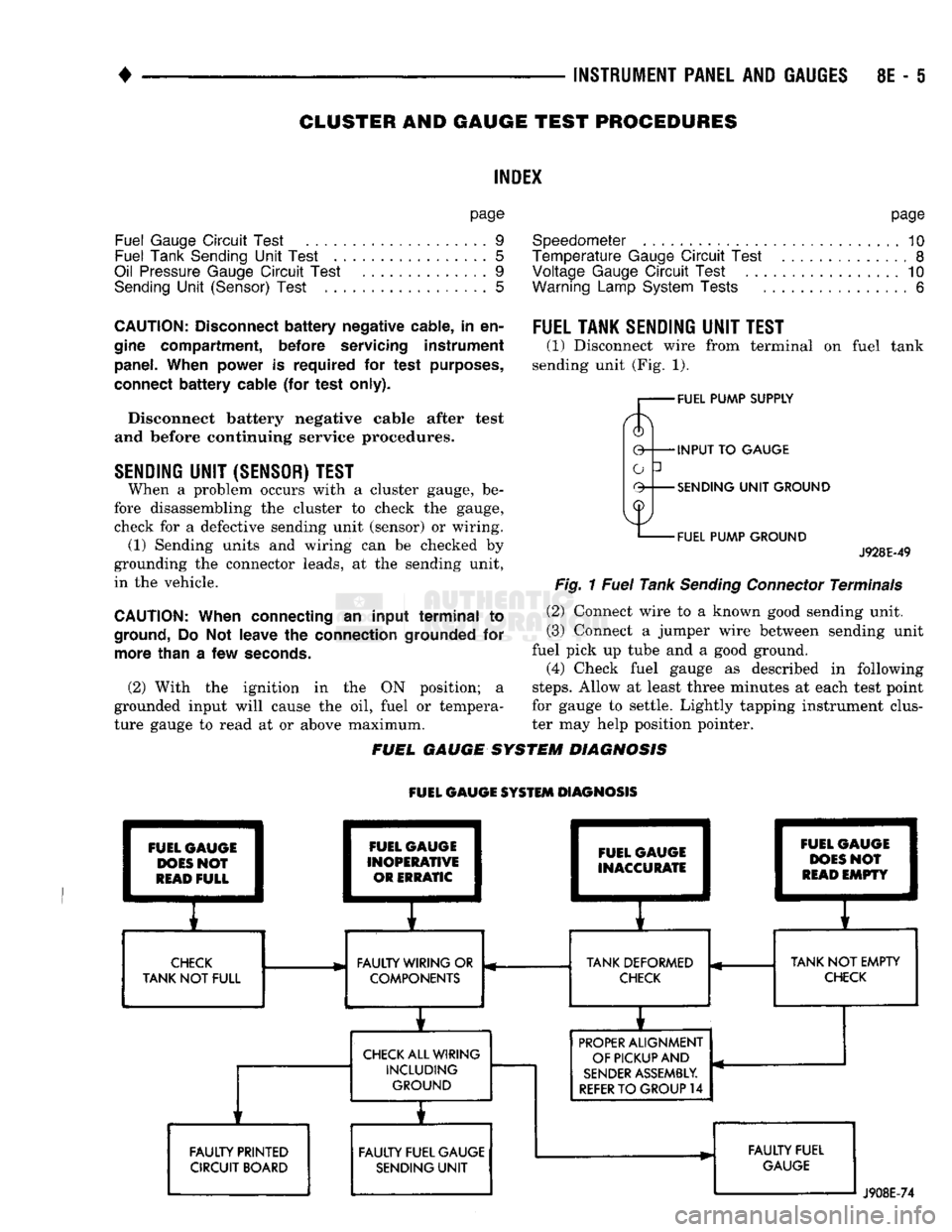
(1) Disconnect wire from terminal
on
fuel tank
sending unit (Fig.
1).
FUEL PUMP SUPPLY
INPUT
TO
GAUGE
SENDING
UNIT
GROUND
FUEL PUMP GROUND
J928E-49
Fig.
1
Fuel
Tank
Sending
Connector
Terminals
(2) Connect wire
to a
known good sending unit.
(3) Connect
a
jumper wire between sending unit
fuel pick
up
tube
and a
good ground.
(4) Check fuel gauge
as
described
in
following
steps.
Allow
at
least three minutes
at
each test point
for gauge
to
settle. Lightly tapping instrument clus
ter
may
help position pointer.
FUEL GAUGE SYSTEM DIAGNOSIS
FUEL GAUGE SYSTEM DIAGNOSIS FUEL GAUGE
DOES
NOT
READ
FULL FAULTY PRINTED
CIRCUIT BOARD FUEL GAUGE
INOPERATIVE OR ERRATIC FUEL GAUGE
INACCURATE
E
1
I
CHECK
FAULTY WIRING
OR
TANK DEFORMED
TANK
NOT
FULL COMPONENTS
CHECK
CHECK
ALL WIRING INCLUDING GROUND
i
FAULTY FUEL GAUGE SENDING
UNIT
i 1
FUEL
C
1
DOES
1
READ
1
pAUGE
I
>N0?
1
EMPTY
1
r
TANK
NOT
EMPTY
CHECK
PROPER
ALIGNMENT
OF PICKUP AND
SENDER
ASSEMBLY.
REFER
TO
GROUP
14
FAULTY FUEL
GAUGE
J908E-74
Page 389 of 1502
8E
- 8 INSTRUMENT PANEL AND GAUGES
•
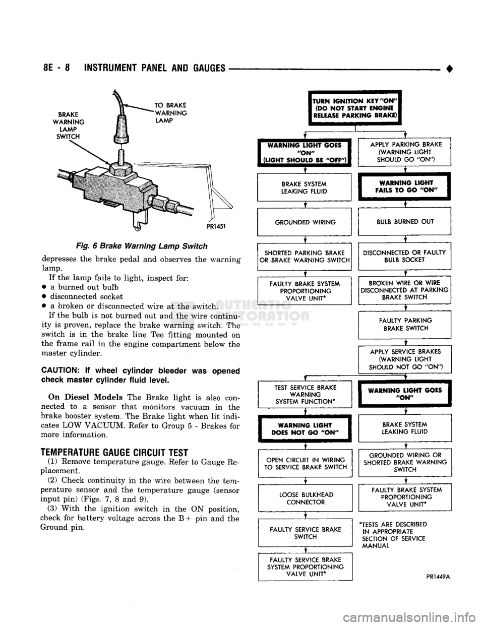
BRAKE
WARNING
LAMP
SWITCH TO BRAKE
WARNING LAMP
PR!
451
Fig.
6
Brake Warning
Lamp
Switch
depresses
the
brake pedal
and
observes
the
warning
lamp.
If
the
lamp fails
to
light, inspect
for:
•
a
burned
out
bulb
• disconnected socket
•
a
broken
or
disconnected wire
at the
switch. If
the
bulb
is not
burned
out and the
wire continu
ity
is
proven, replace
the
brake warning switch.
The
switch
is in the
brake line
Tee
fitting mounted
on
the frame rail
in the
engine compartment below
the
master cylinder.
CAUTION:
If
wheel cylinder bleeder
was
opened
check
master cylinder fluid level.
On Diesel Models
The
Brake light
is
also con
nected
to a
sensor that monitors vacuum
in the
brake booster system.
The
Brake light when
lit
indi cates
LOW
VACUUM. Refer
to
Group
5 -
Brakes
for
more information.
TEMPERATURE
GAUGE CIRCUIT TEST
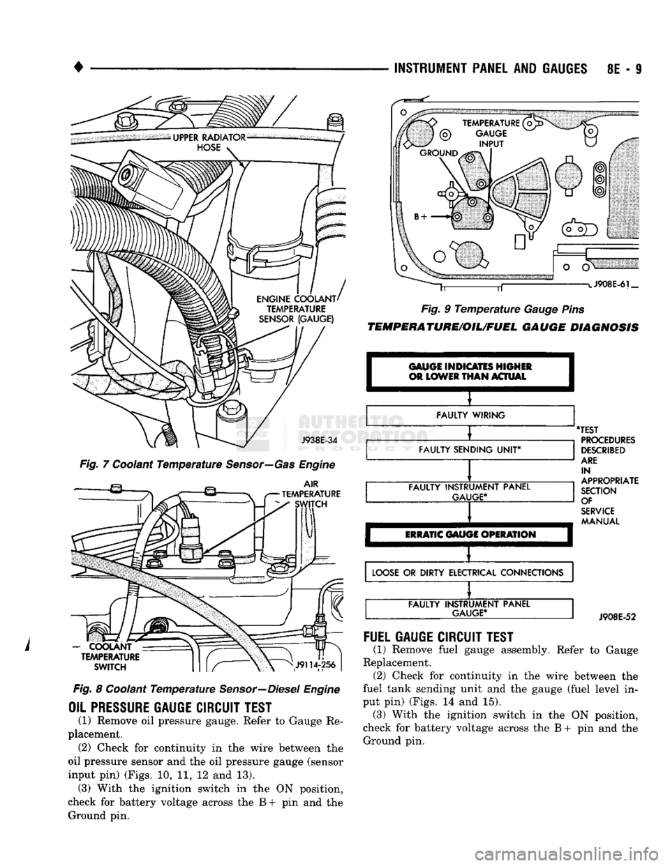
(1) Remove temperature gauge. Refer
to
Gauge
Re
placement. (2) Check continuity
in the
wire between
the
tem
perature sensor
and the
temperature gauge (sensor
input
pin)
(Figs.
7, 8 and 9).
(3) With
the
ignition switch
in the ON
position,
check
for
battery voltage across
the B + pin and the
Ground
pin.
(TURN
IGNITION
KEY
"ON"
(DO
NOT
START
ENGINE
I
RELEASE
PARKING
BRAKE)
I
I
[
WARNING
LIGHT
GOES
I
"ON"
I
1
(LIGHT
SHOULD
BE
"OFF")!
X
APPLY PARKING BRAKE (WARNING
LIGHT
SHOULD
GO "ON")
BRAKE
SYSTEM
LEAKING FLUID
X
WARNING
LIGHT
FAILS
TO GO "ON" GROUNDED WIRING
BULB
BURNED
OUT
SHORTED PARKING BRAKE
OR BRAKE WARNING SWITCH
X
DISCONNECTED
OR
FAULTY
BULB
SOCKET
FAULTY BRAKE SYSTEM PROPORTIONING VALVE
UNIT*
BROKEN
WIRE
OR
WIRE
DISCONNECTED
AT
PARKING
BRAKE
SWITCH
X
FAULTY PARKING
BRAKE
SWITCH
X
APPLY SERVICE BRAKES
(WARNING
LIGHT
SHOULD
NOT GO "ON")
JZ
X
TEST SERVICE BRAKE WARNING
SYSTEM FUNCTION*
X
WARNING
LIGHT
GOES
"ON"
WARNING
LIGHT
DOES
NOT GO "ON"
BRAKE
SYSTEM
LEAKING FLUID
OPEN CIRCUIT
IN
WIRING
TO SERVICE BRAKE SWITCH
X
GROUNDED WIRING
OR
SHORTED BRAKE WARNING SWITCH
LOOSE
BULKHEAD CONNECTOR
X
FAULTY BRAKE SYSTEM
PROPORTIONING VALVE
UNIT*
FAULTY SERVICE BRAKE SWITCH
X
•TESTS
ARE
DESCRIBED
IN APPROPRIATE
SECTION
OF
SERVICE MANUAL
FAULTY SERVICE BRAKE
SYSTEM PROPORTIONING VALVE
UNIT*
PR1449A
Page 390 of 1502
INSTRUMENT
PANEL
AND
GAUGES
8E - S
J938E-34
Fig. 7 Coolant Temperature Sensor—Gas Engine
AIR
TEMPERATURE SWITCH
-
COOLANT TEMPERATURE
SWITCH
Fig. 8 Coolant Temperature Sensor—Diesel Engine
OIL PRESSURE
GAUGE
CIRCUIT
TEST
(1) Remove oil pressure gauge. Refer to Gauge Re
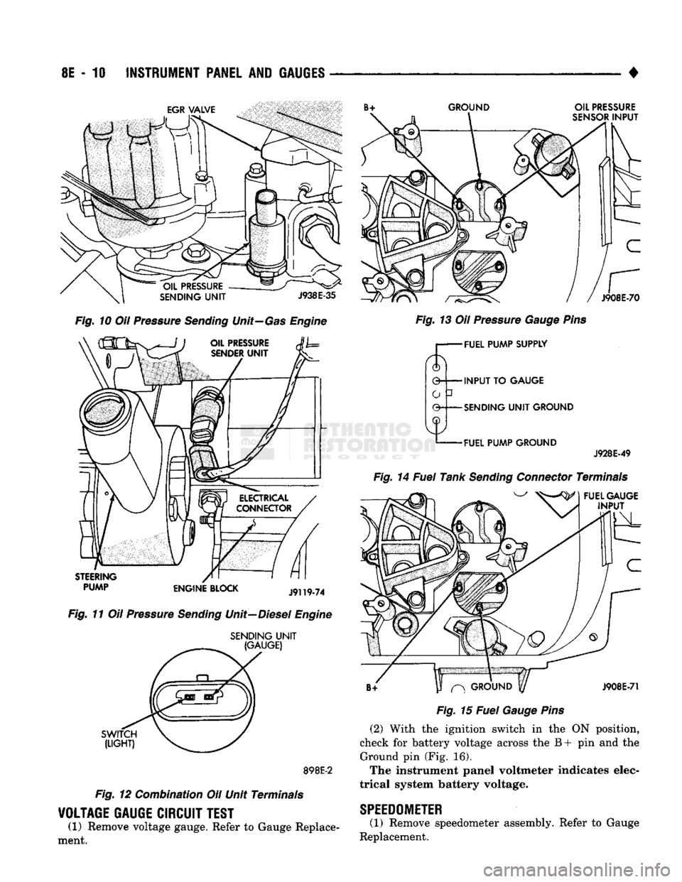
placement. (2) Check for continuity in the wire between the
oil pressure sensor and the oil pressure gauge (sensor
input pin) (Figs. 10, 11, 12 and 13). (3) With the ignition switch in the ON position,
check for battery voltage across the B+ pin and the Ground pin. J908E-6i_
Fig. 9 Temperature Gauge Pins
TEMPERATURE/OIL/FUEL
GAUGE
DIAGNOSIS
GAUGE INDICATES HIGHER
OR
LOWER
THAN
ACTUAL I
FAULTY WIRING
FAULTY SENDING
UNIT*
FAULTY INSTRUMENT PANEL
GAUGE*
ERRATIC
GAUGE OPERATION
'TEST
PROCEDURES
DESCRIBED
ARE
IN
APPROPRIATE
SECTION OF
SERVICE
MANUAL
LOOSE
OR DIRTY ELECTRICAL CONNECTIONS FAULTY INSTRUMENT PANEL
GAUGE*
J908E-52
FUEL
GAUGE
CIRCUIT
TEST
(1) Remove fuel gauge assembly. Refer to Gauge
Replacement. (2) Check for continuity in the wire between the
fuel tank sending unit and the gauge (fuel level in
put pin) (Figs. 14 and 15). (3) With the ignition switch in the ON position,
check for battery voltage across the B + pin and the Ground pin.
Page 391 of 1502
8E
- 10
INSTRUMENT
PANEL
AND
GAUGES
GROUND
OIL
PRESSURE
SENSOR
INPUT
J908E-70
Fig.
10 Oil Pressure
Sending
Unit—Gas Engine
STEERING
PUMP
ENGINE
BLOCK
J9119-74
Fig.
11 Oil Pressure
Sending
Unit—Diesel Engine
SENDING
UNIT
(GAUGE)
SWITCH
(LIGHT)
898E-2
Fig.
12 Combination Oil Unit Terminals
VOLTAGE
GAUGE
CIRCUIT
TEST
(1) Remove voltage gauge. Refer to Gauge Replace
ment.
Fig.
13 Oil Pressure
Gauge
Pins
r— FUEL
PUMP
SUPPLY
0 INPUT TO
GAUGE
-SENDING
UNIT
GROUND
-FUEL
PUMP
GROUND
J928E-49
Fig.
14 Fuel Tank
Sending
Connector Terminals
FUEL
GAUGE
INPUT
^
GROUND
y
J908E-71
Fig.
15 Fuel
Gauge
Pins
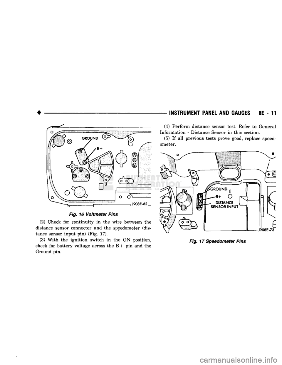
(2) With the ignition switch in the ON position,
check for battery voltage across the B+ pin and the Ground pin (Fig. 16).
The instrument panel voltmeter indicates elec
trical system battery voltage.
SPEEDOMETER
(1) Remove speedometer assembly. Refer to Gauge
Replacement.
Page 392 of 1502
•
Fig.
16
Voltmeter
Pins
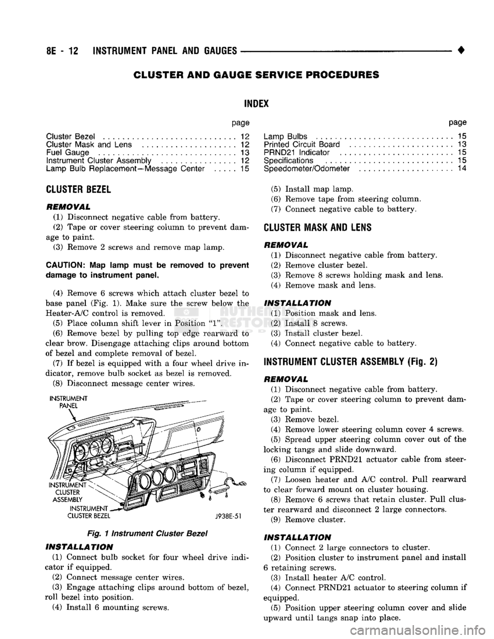
(2) Check for continuity in the wire between the
distance sensor connector and the speedometer (dis
tance sensor input pin) (Fig. 17).
(3) With the ignition switch in the ON position,
check for battery voltage across the B + pin and the Ground pin. —
INSTRUMENT PANEL
AND
GAUGES
8E - 11
Fig.
17 Speedometer
Pins
(4) Perform distance sensor test. Refer to General
Information - Distance Sensor in this section.
(5)
If all previous tests prove good, replace speed
ometer.
Page 393 of 1502
8E
- 12
INSTRUMENT PANEL
AND
GAUGES
•
CLUSTER AND GAUGE
SERVICE
PROCEDURES
INDEX
page
Cluster Bezel
12
Cluster
Mask
and
Lens
12
Fuel Gauge
13
Instrument
Cluster Assembly
12
Lamp Bulb Replacement—Message Center
..... 15
CLUSTER
BEZEL
REMOVAL
(1) Disconnect negative cable from battery.
(2) Tape
or
cover steering column
to
prevent dam
age
to
paint.
(3) Remove
2
screws and remove map lamp.
CAUTION:
Map
lamp must
be
removed
to
prevent
damage
to
instrument panel.
(4) Remove
6
screws which attach cluster bezel
to
base panel (Fig.
1).
Make sure
the
screw below
the
Heater-A/C control
is
removed.
(5)
Place column shift lever
in
Position
"1".
(6) Remove bezel
by
pulling
top
edge rearward
to
clear brow. Disengage attaching clips around bottom
of bezel
and
complete removal
of
bezel.
(7)
If
bezel
is
equipped with
a
four wheel drive
in
dicator, remove bulb socket
as
bezel
is
removed.
(8) Disconnect message center wires.
INSTRUMENT
CLUSTER BEZEL
J938E-51
Fig.
1 instrument
Cluster
Bezel
INSTALLATION
(1) Connect bulb socket
for
four wheel drive indi
cator
if
equipped.
(2)
Connect message center wires.
(3) Engage attaching clips around bottom
of
bezel,
roll bezel into position.
(4) Install
6
mounting screws. page
Lamp Bulbs
. . 15
Printed
Circuit
Board
13
PRND21
Indicator
. 15
Specifications
15
Speedometer/Odometer
14
(5)
Install map lamp.
(6) Remove tape from steering column.
(7) Connect negative cable
to
battery.
CLUSTER
MASK AND LENS REMOVAL
(1) Disconnect negative cable from battery.
(2) Remove cluster bezel.
(3) Remove
8
screws holding mask
and
lens.
(4) Remove mask
and
lens.
INSTALLATION
(1) Position mask
and
lens.
(2) Install
8
screws.
(3) Install cluster bezel.
(4) Connect negative cable
to
battery.
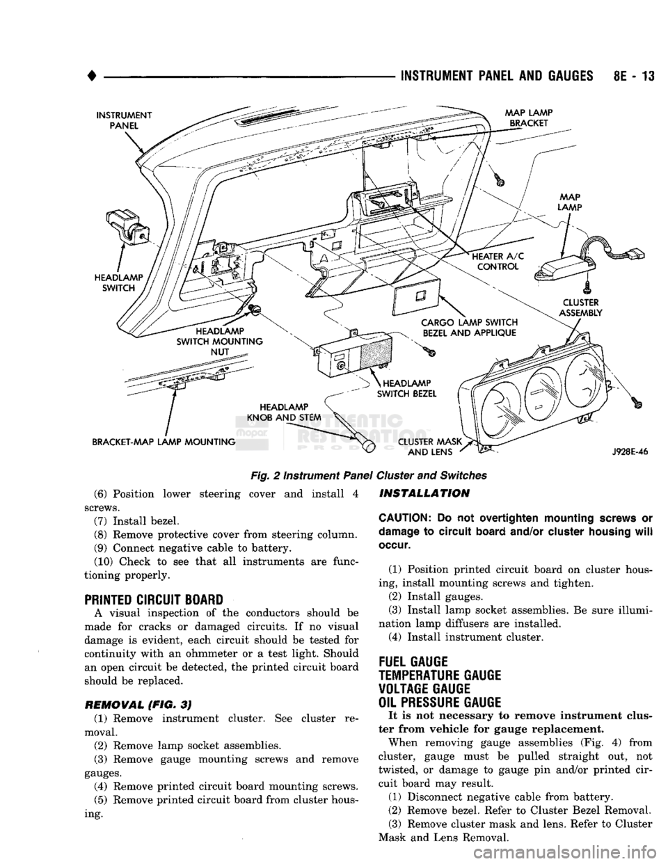
INSTRUMENT CLUSTER ASSEMBLY
(Fig.
2)
REMOVAL
(1) Disconnect negative cable from battery.
(2) Tape
or
cover steering column
to
prevent dam
age
to
paint.
(3) Remove bezel.
(4) Remove lower steering column cover
4
screws.
(5)
Spread upper steering column cover
out of
the
locking tangs
and
slide downward. (6) Disconnect PRND21 actuator cable from steer
ing column
if
equipped.
(7) Loosen heater
and
A/C control. Pull rearward
to clear forward mount
on
cluster housing.
(8) Remove
6
screws that retain cluster. Pull clus
ter rearward
and
disconnect
2
large connectors.
(9) Remove cluster.
INSTALLATION
(1) Connect
2
large connectors
to
cluster.
(2) Position cluster
to
instrument panel and install
6 retaining screws.
(3) Install heater A/C control.
(4) Connect PRND21 actuator
to
steering column
if
equipped.
(5)
Position upper steering column cover
and
slide
upward until tangs snap into place.
Page 394 of 1502
INSTRUMENT PANEL
AND
GAUGES
8E - 13
INSTRUMENT
PANEL MAP LAMP
BRACKET
HEADLAMP
SWITCH
CLUSTER
ASSEMBLY
HEADLAMP
SWITCH
MOUNTING
NUT CARGO LAMP
SWITCH
BEZEL
AND
APPLIQUE
HEADLAMP
KNOB
AND
STEM
BRACKET-AAAP LAMP
MOUNTING
Fig.
2 Instrument
Panel
(6) Position lower steering cover and install 4
screws.
(7)
Install bezel.
(8)
Remove protective cover from steering column.
(9) Connect negative cable to battery. (10) Check to see that all instruments are func
tioning properly.
PRINTED CIRCUIT BOARD
A visual inspection of the conductors should be
made for cracks or damaged circuits. If no visual
damage is evident, each circuit should be tested for continuity with an ohmmeter or a test light. Should an open circuit be detected, the printed circuit board
should be replaced.
REMOVAL (FIG. 3J (1) Remove instrument cluster. See cluster re
moval.
(2)
Remove lamp socket assemblies.
(3) Remove gauge mounting screws and remove
gauges.
(4) Remove printed circuit board mounting screws.
(5)
Remove printed circuit board from cluster hous
ing.
HEADLAMP
SWITCH
BEZEL
CLUSTER MASK AND LENS
J928E-46
Cluster
and
Switches
INSTALLATION
CAUTION:
Do not overtighten mounting
screws
or
damage
to circuit
board
and/or
cluster
housing
will
occur.
(1) Position printed circuit board on cluster hous
ing, install mounting screws and tighten.
(2)
Install gauges.
(3) Install lamp socket assemblies. Be sure illumi
nation lamp diffusers are installed. (4) Install instrument cluster.
FUEL GAUGE
TEMPERATURE
GAUGE VOLTAGE GAUGE
OIL
PRESSURE
GAUGE
It is not necessary to remove instrument clus
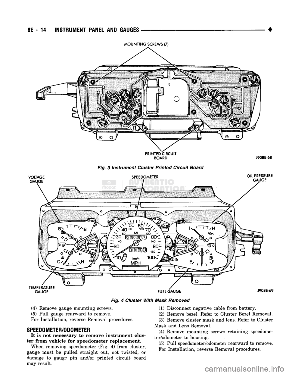
ter from vehicle for gauge replacement. When removing gauge assemblies (Fig. 4) from
cluster, gauge must be pulled straight out, not
twisted, or damage to gauge pin and/or printed cir cuit board may result. (1) Disconnect negative cable from battery.
(2)
Remove bezel. Refer to Cluster Bezel Removal. (3) Remove cluster mask and lens. Refer to Cluster
Mask and Lens Removal.
Page 395 of 1502
8E
- 14
INSTRUMENT
PANEL
AND
GAUGES
•
VOLTAGE
GAUGE
Fig. 3 instrument Cluster Printed Circuit Board
SPEEDOMETER OIL
PRESSURE
GAUGE
TEMPERATURE GAUGE
FUEL
GAUGE
Fig. 4 Cluster With Mask Removed
J908E-69
(4)
Remove gauge mounting screws.
(5) Pull gauge rearward to remove.
For Installation, reverse Removal procedures.
SPEEDOMETER/ODOMETER
It is not necessary to remove instrument clus
ter from vehicle for speedometer replacement. When removing speedometer (Fig. 4) from cluster,
gauge must be pulled straight out, not twisted, or
damage to gauge pin and/or printed circuit board
may result. (1) Disconnect negative cable from battery.
(2) Remove bezel. Refer to Cluster Bezel Removal.
(3) Remove cluster mask and lens. Refer to Cluster
Mask and Lens Removal. (4) Remove mounting screws retaining speedome
ter/odometer to housing.
(5) Pull speedometer/odometer rearward to remove.
For Installation, reverse Removal procedures.