1993 DODGE TRUCK wheel bolt torque
[x] Cancel search: wheel bolt torquePage 653 of 1502
9
• 48 5.2L
ENGINE
•
CAUTION;
DO NOT lift the
engine
by the
intake
manifold.
(2) Install an engine lifting fixture.
(3) Raise vehicle on hoist.
(4) Remove nuts from brackets and insulators (Fig.
4).
(5) Raise engine with lifting fixture only far
enough to remove insulators.
SCREW
<£>
SCREW
<1j>
FRONT
LOCATING PIN
" ON LEFT
SIDE
ONLY
USE
FRONT HOLES
FOR
INSULATOR MTG,
2-WHEEL DRIVE TIGHTENING TORQUE
75
FT. LBS. (102 N-m)
65 FT. LBS. (88 N.m)
<£>
30 FT. LBS.
(41
N-m)
NUT
WASHER
BRACKET'
INSULATOR
<
LEFTSIDE
4-WHEEL DRIVE
FRAME SHOWN INSULATOR
BRACKET
(FRONT ENG SUPPORT)
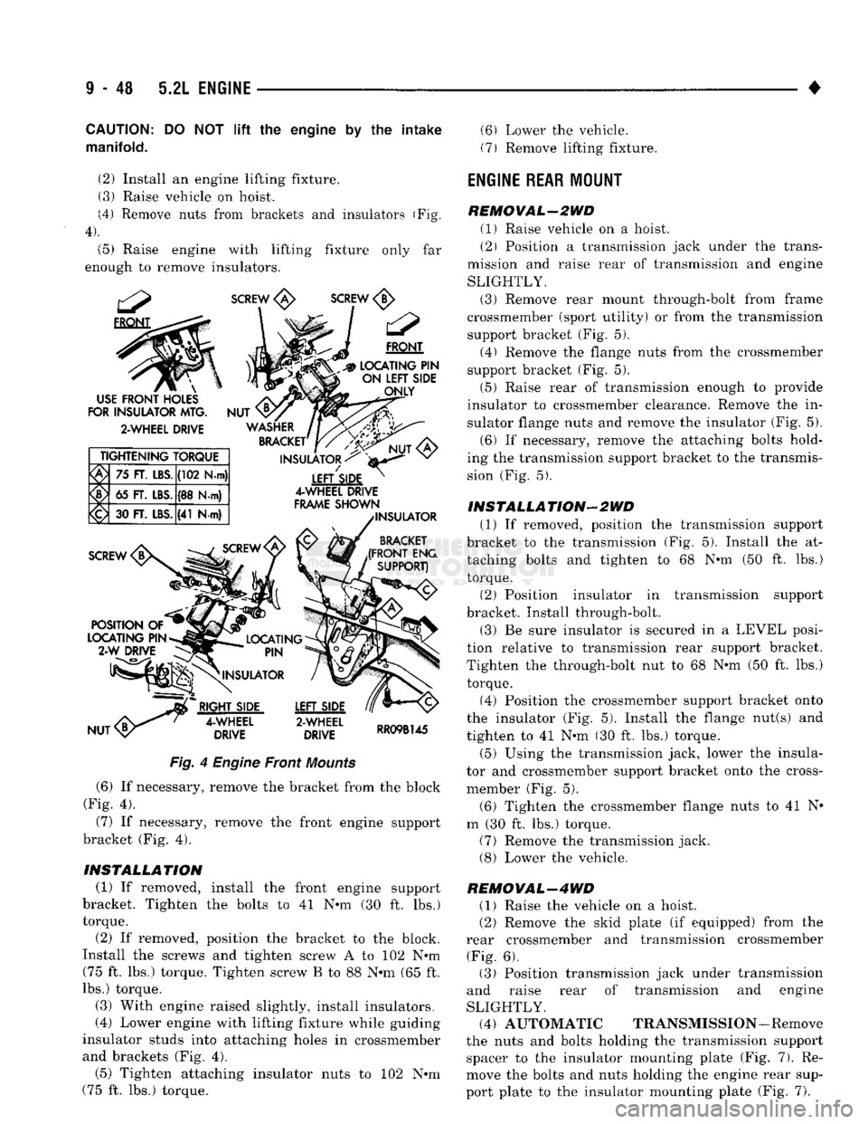
Fig.
4
Engine
Front
Mounts
(6) If necessary, remove the bracket from the block
(Fig. 4).
(7) If necessary, remove the front engine support
bracket (Fig. 4).
INSTALLATION (1) If removed, install the front engine support
bracket. Tighten the bolts to 41 N-m (30 ft. lbs.)
torque.
(2) If removed, position the bracket to the block.
Install the screws and tighten screw A to 102 N-m (75 ft. lbs.) torque. Tighten screw B to 88 N-m (65 ft.
lbs.) torque.
(3) With engine raised slightly, install insulators.
(4) Lower engine with lifting fixture while guiding
insulator studs into attaching holes in crossmember
and brackets (Fig. 4). (5) Tighten attaching insulator nuts to 102 N-m
(75 ft. lbs.) torque. (6) Lower the vehicle.
(7) Remove lifting fixture.
ENGINE REAR
MOUNT
REMOVAL-2WD (1) Raise vehicle on a hoist.
(2) Position a transmission jack under the trans
mission and raise rear of transmission and engine
SLIGHTLY. (3) Remove rear mount through-bolt from frame
crossmember (sport utility) or from the transmission support bracket (Fig. 5). (4) Remove the flange nuts from the crossmember
support bracket (Fig. 5).
(5) Raise rear of transmission enough to provide
insulator to crossmember clearance. Remove the in
sulator flange nuts and remove the insulator (Fig. 5). (6) If necessary, remove the attaching bolts hold
ing the transmission support bracket to the transmis
sion (Fig. 5).
INSTALLATION-2WD (1) If removed, position the transmission support
bracket to the transmission (Fig. 5). Install the at taching bolts and tighten to 68 N-m (50 ft. lbs.)
torque.
(2) Position insulator in transmission support
bracket. Install through-bolt.
(3) Be sure insulator is secured in a LEVEL posi
tion relative to transmission rear support bracket.
Tighten the through-bolt nut to 68 N-m (50 ft. lbs.) torque.
(4) Position the crossmember support bracket onto
the insulator (Fig. 5). Install the flange nut(s) and
tighten to 41 N-m (30 ft. lbs.) torque.
(5) Using the transmission jack, lower the insula
tor and crossmember support bracket onto the cross-
member (Fig. 5).
(6) Tighten the crossmember flange nuts to 41 N-
m (30 ft. lbs.) torque. (7) Remove the transmission jack. (8) Lower the vehicle.
REMOVAL-4WD (1) Raise the vehicle on a hoist.
(2) Remove the skid plate (if equipped) from the
rear crossmember and transmission crossmember (Fig. 6). (3) Position transmission jack under transmission
and raise rear of transmission and engine
SLIGHTLY. (4) AUTOMATIC TRANSMISSION-Remove
the nuts and bolts holding the transmission support spacer to the insulator mounting plate (Fig. 7). Re
move the bolts and nuts holding the engine rear sup
port plate to the insulator mounting plate (Fig. 7).
Page 683 of 1502
9
- 78 5.9L ENGINE
•
CAUTION:
DO NOT
lift
the engine by the
intake
manifold.
(2)
Install an engine lifting fixture.
(3) Raise vehicle on hoist.
(4) Remove nuts from brackets and insulators (Fig,
4).
(5) Raise engine with lifting fixture only far
enough to remove insulators.
SCREW
<£>
SCREW
FRONT
#C3p
LOCATING
PIN
- -•- —
SIDE
ONLY
INSULATORS
^
4-WHEEL DRIVE
FRAME
SHOWN
INSULATOR
BRACKET
(FRONT
ENG
SUPPORT)
USE
FRONT
HOLES
FOR
INSULATOR
MTG.
2-WHEEL DRIVE
TIGHTENING TORQUE
75
FT.
LBS.
(102 N-m)
65
FT.
LBS.
(38
Hw)
<£) 30
FT.
LBS.
(41
N-m)
RIGHT
SIDE
4-WHEEL
DRIVE
LEFT
SIDE
2-WHEEL
DRIVE
RR09B145
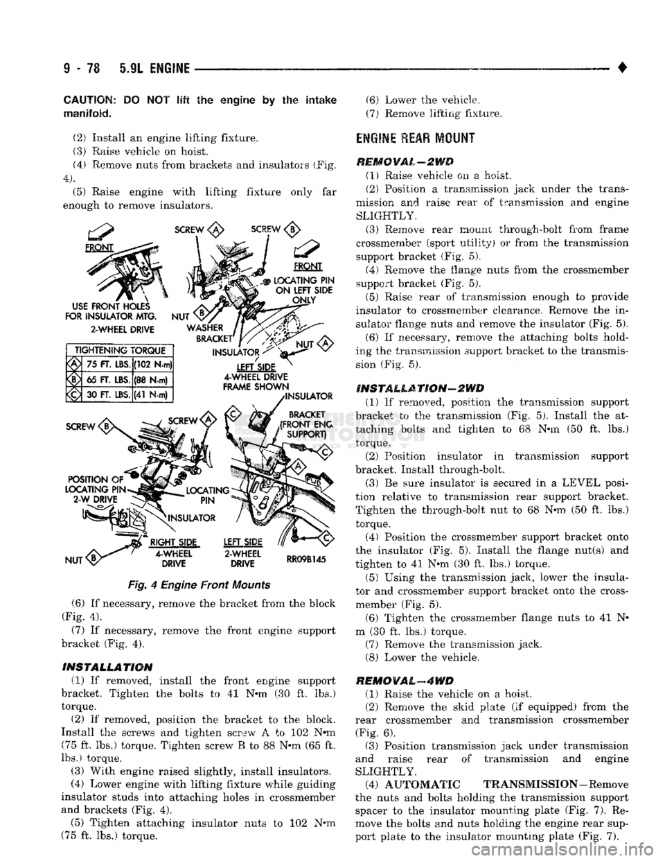
Fig.
4 Engine Front
Mounts
(6) If necessary, remove the bracket from the block
(Fig. 4).
(7)
If necessary, remove the front engine support
bracket (Fig. 4).
INSTALLATION
(1) If removed, install the front engine support
bracket. Tighten the bolts to 41 N-m (30 ft. lbs.)
torque.
(2) If removed, position the bracket to the block.
Install the screws and tighten screw A to 102 Nrn (75 ft. lbs.) torque. Tighten screw B to 88 N-m (65 ft.
lbs.) torque.
(3) With engine raised slightly, install insulators.
(4) Lower engine with lifting fixture while guiding
insulator studs into attaching holes in crossmember and brackets (Fig. 4). (5) Tighten attaching insulator nuts to 102 N-m
(75 ft. lbs.) torque. (6) Lower the vehicle.
(7)
Remove lifting fixture.
engine rear
MOUNT
REMCYAL-2WD (1) Raise vehicle on a hoist.
(2) Position a transmission jack under the trans
mission and raise rear of transmission and engine SLIGHTLY.
(3) Remove rear mount through-bolt from frame
crossmember (sport utility) or from the transmission support bracket (Fig. 5).
(4) Remove the flange nuts from the crossmember
support bracket (Fig. 5).
(5) Raise rear of transmission enough to provide
insulator to crossmember clearance. Remove the in
sulator flange nuts and remove the insulator (Fig. 5).
(6) If necessary, remove the attaching bolts hold
ing the transmission support bracket to the transmis sion (Fig. 5).
INSTALLATION-2WD (1) If removed, position the transmission support
bracket to the transmission (Fig. 5). Install the at
taching bolts and tighten to 68 N-m (50 ft. lbs.) torque. (2) Position insulator in transmission support
bracket. Install through-bolt.
(3) Be sure insulator is secured in a LEVEL posi
tion relative to transmission rear support bracket. Tighten the through-bolt nut to 68 N-m (50 ft. lbs.) torque.
(4) Position the crossmember support bracket onto
the insulator (Fig. 5). Install the flange nut(s) and
tighten to 41 N-m (30 ft. lbs.) torque.
(5)
Using the transmission jack, lower the insula
tor and crossmember support bracket onto the cross-
member (Fig. 5).
(6) Tighten the crossmember flange nuts to 41 N-
m (30 ft. lbs.) torque. (7) Remove the transmission jack.
(8) Lower the vehicle.
REMOVAL-4WD
(1) Raise the vehicle on a hoist.
(2) Remove the skid plate (if equipped) from the
rear crossmember and transmission crossmember (Fig. 6). (3) Position transmission jack under transmission
and raise rear of transmission and engine
SLIGHTLY. (4) AUTOMATIC TRANSMISSION-Remove
the nuts and bolts holding the transmission support spacer to the insulator mounting plate (Fig. 7). Re
move the bolts and nuts holding the engine rear sup
port plate to the insulator mounting plate (Fig. 7).
Page 721 of 1502
9
- 116 5.9L
(DIESEL) ENGINE
•
CYLINDER HEAD
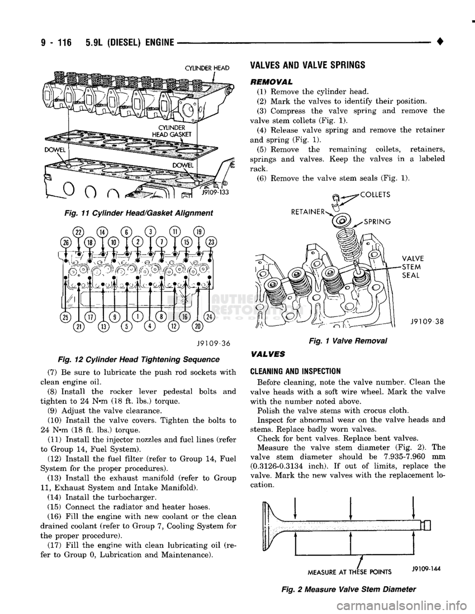
Fig. 11 Cylinder Head/Gasket Alignment J9109-36
Fig. 12 Cylinder Head Tightening Sequence
(7) Be sure to lubricate the push rod sockets with
clean engine oil.
(8) Install the rocker lever pedestal bolts and
tighten to 24 N*m (18 ft. lbs.) torque. (9) Adjust the valve clearance.
(10) Install the valve covers. Tighten the bolts to
24 N*m (18 ft. lbs.) torque.
(11) Install the injector nozzles and fuel lines (refer
to Group 14, Fuel System).
(12) Install the fuel filter (refer to Group 14, Fuel
System for the proper procedures). (13) Install the exhaust manifold (refer to Group
11,
Exhaust System and Intake Manifold).
(14) Install the turbocharger.
(15) Connect the radiator and heater hoses. (16) Fill the engine with new coolant or the clean
drained coolant (refer to Group 7, Cooling System for
the proper procedure). (17) Fill the engine with clean lubricating oil (re
fer to Group 0, Lubrication and Maintenance).
VALVES
AND VALVE
SPRINGS
REMOWAL
(1) Remove the cylinder head.
(2) Mark the valves to identify their position.
(3) Compress the valve spring and remove the
valve stem collets (Fig. 1). (4) Release valve spring and remove the retainer
and spring (Fig. 1).
(5) Remove the remaining collets, retainers,
springs and valves. Keep the valves in a labeled
rack.
(6) Remove the valve stem seals (Fig. 1). -38
Fig. 1 Valve Removal
WALVES
CLEANING AND INSPECTION
Before cleaning, note the valve number. Clean the
valve heads with a soft wire wheel. Mark the valve
with the numbet* noted above.
Polish the valve stems with crocus cloth.
Inspect for abnormal wear on the valve heads and
stems.
Replace badly worn valves. Check for bent valves. Replace bent valves.
Measure the valve stem diameter (Fig. 2). The
valve stem diameter should be 7.935-7.960 mm (0.3126-0.3134 inch). If out of limits, replace the
valve. Mark the new valves with the replacement lo cation. Ik 1
MEASURE
AT THESE POINTS
Fig. 2 Measure Valve Stem Diameter
Page 730 of 1502
•
5JL
(DIESEL) ENGINE
9 - 125 (14) Reset the valves on No.l cylinder and install
valve cover.
(15) Install timing pin housing assembly and a
new gasket.
(16) Apply a coat of Loctite 59241 Liquid Teflon, or
equivalent to the threads of the Torx head bolts. (17) Hold the timing pin in the hole to align the
housing and install the Torx head bolts. Tighten the
Torx bolts to 5 N»m (44 in. lbs.) torque.
(18) Install the injectors and bleed the fuel system
(refer to Group 14, Fuel System).
INSTALLATION
(CYLINDER
HEAD
OFF) The timing pin assembly is precisely located on the
gear housing to correspond to TDC for Cylinder No.l.
The timing pin assembly must be relocated if the gear housing is interchanged.
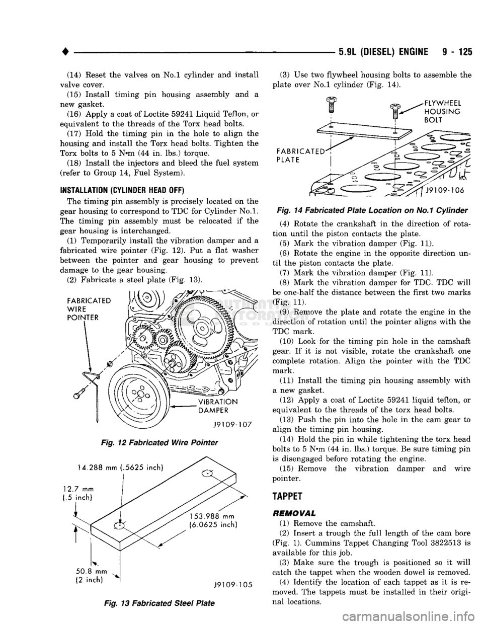
(1) Temporarily install the vibration damper and a
fabricated wire pointer (Fig. 12). Put a flat washer
between the pointer and gear housing to prevent damage to the gear housing.
(2) Fabricate a steel plate (Fig. 13).
Fig.
12 Fabricated
Wire
Pointer
Fig.
13 Fabricated
Steel
Plate
(3) Use two flywheel housing bolts to assemble the
plate over No.l cylinder (Fig. 14).
Fig.
14 Fabricated
Plate
Location on No.1 Cylinder (4) Rotate the crankshaft in the direction of rota
tion until the piston contacts the plate.
(5) Mark the vibration damper (Fig. 11).
(6) Rotate the engine in the opposite direction un
til the piston contacts the plate. (7) Mark the vibration damper (Fig. 11).
(8) Mark the vibration damper for TDC. TDC will
be one-half the distance between the first two marks (Fig. 11).
(9) Remove the plate and rotate the engine in the
direction of rotation until the pointer aligns with the
TDC mark. (10) Look for the timing pin hole in the camshaft
gear. If it is not visible, rotate the crankshaft one
complete rotation. Align the pointer with the TDC
mark.
(11) Install the timing pin housing assembly with
a new gasket. (12) Apply a coat of Loctite 59241 liquid teflon, or
equivalent to the threads of the torx head bolts.
(13) Push the pin into the hole in the cam gear to
align the timing pin housing.
(14) Hold the pin in while tightening the torx head
bolts to 5 Nnn (44 in. lbs.) torque. Be sure timing pin is disengaged before rotating the engine.
(15) Remove the vibration damper and wire
pointer.
TAPPET
REMOVAL (1) Remove the camshaft. (2) Insert a trough the full length of the cam bore
(Fig. 1). Cummins Tappet Changing Tool 3822513 is
available for this job.
(3) Make sure the trough is positioned so it will
catch the tappet when the wooden dowel is removed. (4) Identify the location of each tappet as it is re
moved. The tappets must be installed in their origi
nal locations.
Page 756 of 1502
5.9L
(DIESEL)
ENGINE
9-153
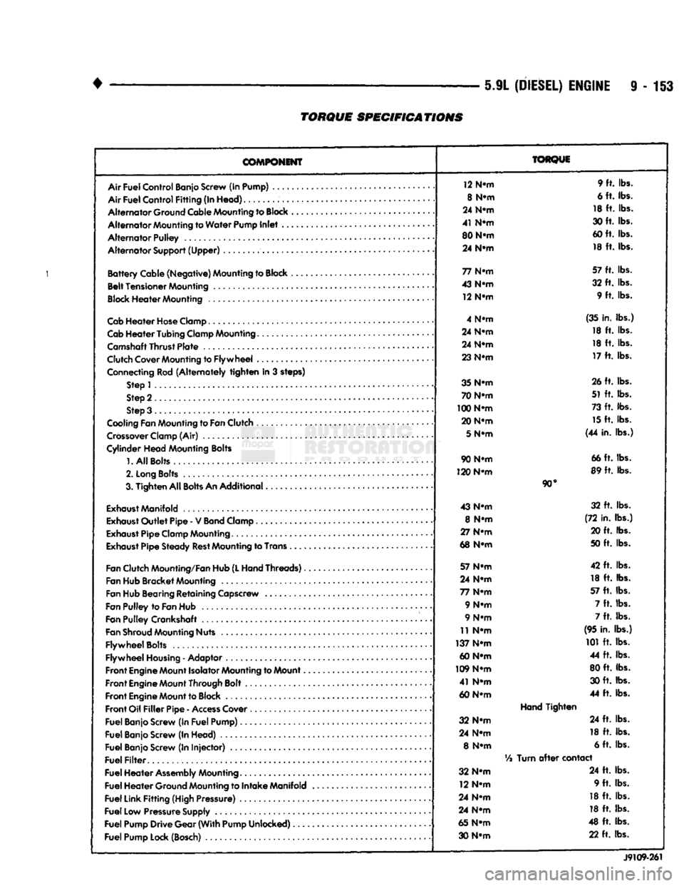
TORQUE
SPECIFICATIONS
COMPONENT
Air
Fuel
Control
Banjo Screw (In Pump) ....
Air
Fuel
Control
Fitting
(In
Head)
Alternator
Ground Cable Mounting to
Block
Alternator
Mounting to
Water
Pump
Inlet
..
Alternator
Pulley
Alternator
Support
(Upper)
Battery
Cable
(Negative)
Mounting to Block ,
Belt
Tensioner
Mounting
Block
Heater
Mounting
Cab
Heater
Hose
Clamp
Cab
Heater
Tubing
Clamp Mounting.......
Camshaft
Thrust
Plate
Clutch Cover Mounting to
Flywheel
...
Connecting Rod
(Alternately
tighten
in 3 steps) Step 1
Step 2
Step 3 .
Cooling Fan Mounting to
Fan
Clutch
Crossover
Clamp (Air)
Cylinder
Head
Mounting Bolts
1.
All
Bolts....
2.
Long
Bolts
.........
3.
Tighten
All
Bolts
An
Additional
Exhaust
Manifold
Exhaust
Outlet
Pipe
- V
Band
Clamp
Exhaust
Pipe
Clamp Mounting
Exhaust
Pipe
Steady
Rest
Mounting to Trans .
Fan
Clutch Mounting/Fan Hub
(L
Hand
Threads)..
Fan Hub
Bracket
Mounting
Fan Hub Bearing
Retaining
Capscrew
Fan
Pulley
to
Fan
Hub
Fan
Pulley
Crankshaft .
Fan
Shroud
Mounting Nuts
Flywheel
Bolts
Flywheel
Housing
- Adaptor
Front
Engine
Mount Isolator Mounting to Mount..
Front
Engine
Mount Through Bolt
Front
Engine
Mount to Block
Front
Oil
Filler
Pipe
-
Access
Cover
Fuel
Banjo Screw (In
Fuel
Pump)
Fuel
Banjo Screw (In
Head)
Fuel
Banjo Screw (In
Injector)
Fuel
Filter
Fuel
Heater
Assembly
Mounting
Fuel
Heater
Ground Mounting to
Intake
Manifold
Fuel
Link
Fitting
(High Pressure)
Fuel
Low Pressure Supply
Fuel
Pump
Drive
Gear
(With
Pump
Unlocked)
Fuel
Pump Lock (Bosch)
TORQUE
12 N-m 9 ft. lbs.
8 N-m 6 ft. lbs.
24 N-m 18 ft. lbs.
41 N*m 30 ft. lbs.
80 N-m 60 ft. lbs.
24 N-m 18 ft. lbs.
77 N-m 57 ft. lbs.
43 N-m 32 ft. lbs.
12 N-m 9 ft. lbs.
4 N-m (35 in. lbs.)
24 N-m 18 ft. lbs.
24 N-m 18 ft. lbs.
23 N-m 17 ft. lbs.
35 N-m 26 ft. lbs.
70 N-m 51 ft. lbs.
100 N-m 73 ft. lbs.
20 N-m 15 ft. lbs.
5
N-m (44 in. lbs.)
90 N-m 66 ft. lbs.
120 N-m 89 ft. lbs.
90°
43 N-m 32 ft. lbs.
8 N-m (72 in. lbs.)
27 N-m 20 ft. lbs.
68 N-m 50 ft. lbs.
57 N-m 42 ft. lbs.
24 N-m 18 ft. lbs.
77 N-m 57 ft. lbs.
9 N-m 7 ft. lbs.
9 N-m 7 ft. lbs.
11 N-m (95 in. lbs.)
137 N-m 101 ft. lbs.
60 N-m 44 ft. lbs.
109 N-m 80 ft. lbs.
41 N-m 30 ft. lbs.
60 N-m 44 ft. lbs.
Hand
Tighten
32 N-m 24 ft. lbs.
24 N-m 18 ft. lbs.
8 N-m 6 ft. lbs.
Vi
Turn
after
contact
32 N-m 24 ft. lbs.
12 N-m 9 ft. lbs.
24 N-m 18 ft. lbs.
24 N-m 18 ft. lbs.
65 N-m 48 ft. lbs.
30 N-m 22 ft. lbs.
J9109-261
Page 776 of 1502
•
EXHAUST SYSTEM AND INTAKE MANIFOLD 11 - 17 8ERY1CE PROCEDURES
(DIESEL ENGINES)
INDEX
page
Charge
Air
Cooler
(Intercooler)
25
Engine
Exhaust
Manifold
18
Exhaust
Pipe
17
Exhaust
Tailpipe
18
EXHAUST PIPE
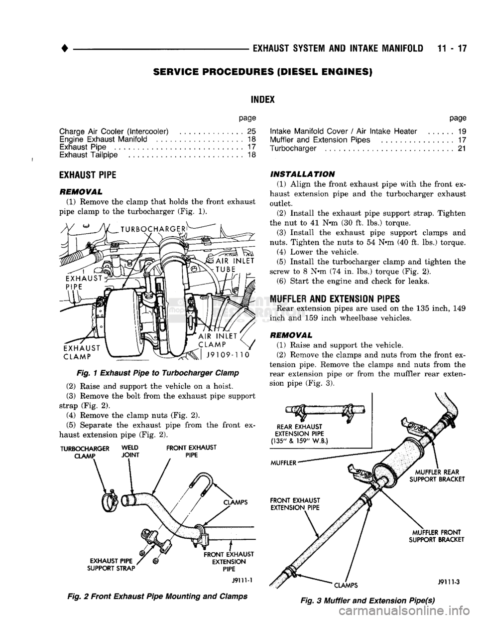
REMOVAL
(1) Remove the clamp that holds the front exhaust
pipe clamp to the turbocharger (Fig. 1).
Fig.
1
Exhaust
Pipe to Turbocharger
Clamp
(2)
Raise and support the vehicle on a hoist.
(3)
Remove the bolt from the exhaust pipe support
strap (Fig. 2).
(4)
Remove the clamp nuts (Fig. 2).
(5)
Separate the exhaust pipe from the front ex
haust extension pipe (Fig. 2).
TURBOCHARGER WELD
FRONT
EXHAUST
CLAMP
JOINT
PIPE
SUPPORT STRAP
PIPE
J911M
Fig.
2 Front
Exhaust
Pipe
Mounting
and
Clamps
page
Intake
Manifold
Cover
/ Air
Intake
Heater
19
Muffler
and
Extension
Pipes
17
Turbocharger
21
INSTALLATION
(1)
Align the front exhaust pipe with the front ex
haust extension pipe and the turbocharger exhaust outlet.
(2)
Install the exhaust pipe support strap. Tighten
the nut to 41 Nun (30 ft. lbs.) torque.
(3)
Install the exhaust pipe support clamps and
nuts.
Tighten the nuts to 54 Nun (40 ft. lbs.) torque.
(4)
Lower the vehicle.
(5)
Install the turbocharger clamp and tighten the
screw to 8 Nun (74 in. lbs.) torque (Fig. 2). (6) Start the engine and check for leaks.
MUFFLER AND EXTENSION PIPES Rear extension pipes are used on the 135 inch, 149
inch and 159 inch wheelbase vehicles.
REMOVAL
(1)
Raise and support the vehicle.
(2)
Remove the clamps and nuts from the front ex
tension pipe. Remove the clamps and nuts from the rear extension pipe or from the muffler rear extension pipe (Fig. 3).
Fig.
3 Muffler and Extension Pipe(s)
Page 782 of 1502
•
EXHAUST
SYSTEM
AND
INTAKE MANIFOLD
11 - 23
HEAT
SHIELD
OUTER RETAINER
RINGS
BREAKING,
HOUSING
J9111-18
Fig.
24 Turbine Shaft/Heat
Shield
to Bearing
Housing
INNER
RETAINING
RINGS
INNER
RETAINING RING
J9111-14
Fig.
22
Snap Rings
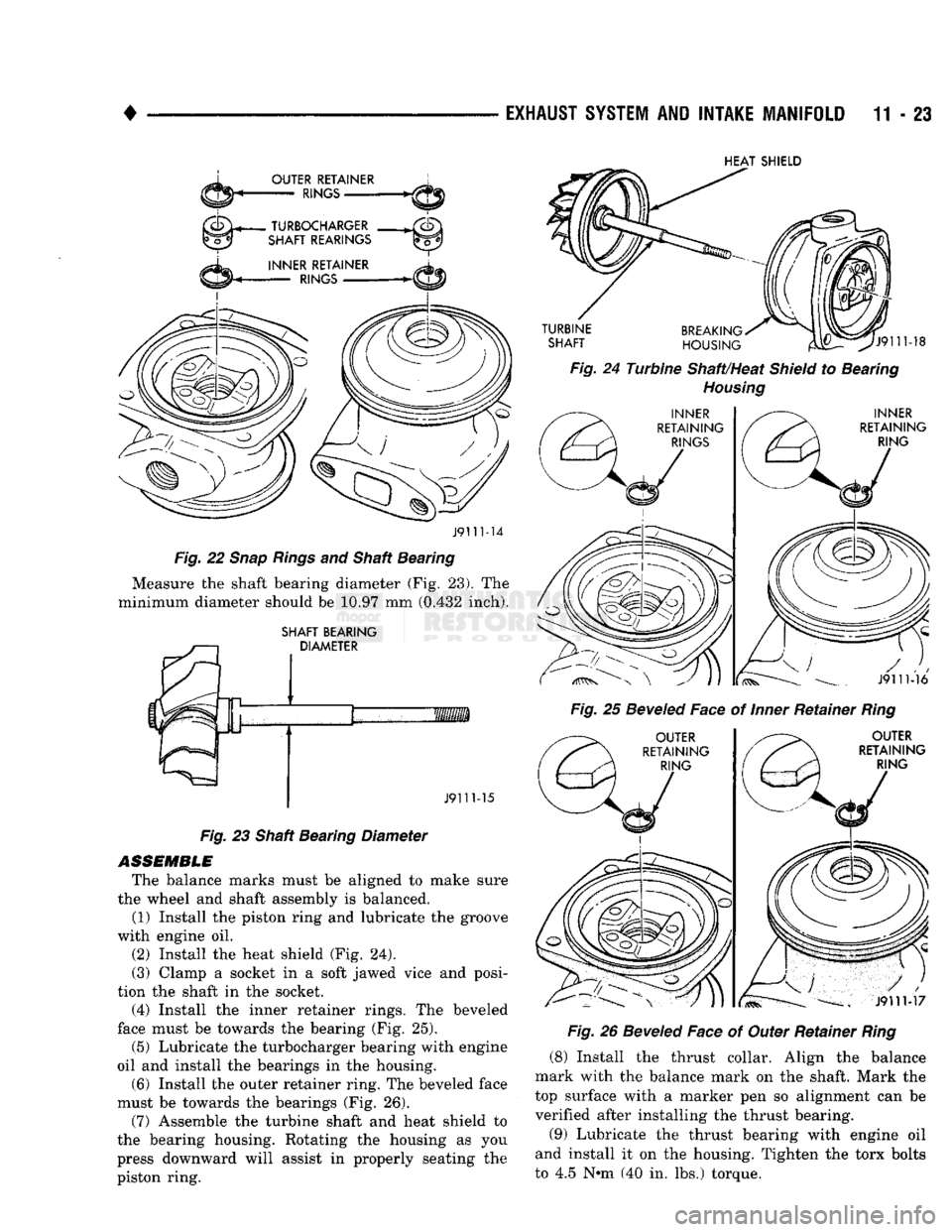
and Shaft Bearing Measure the shaft bearing diameter (Fig. 23). The
minimum diameter should be 10.97 mm (0.432 inch).
SHAFT BEARING DIAMETER Fig.
25
Beveled
Face of
Inner
Retainer
Ring
J911M6
OUTER
RETAINING RING
J9111-15
Fig.
23 Shaft Bearing Diameter
ASSEMBLE
The balance marks must be aligned to make sure
the wheel and shaft assembly is balanced. (1) Install the piston ring and lubricate the groove
with engine oil.
(2) Install the heat shield (Fig. 24).
(3) Clamp a socket in a soft jawed vice and posi
tion the shaft in the socket. (4) Install the inner retainer rings. The beveled
face must be towards the bearing (Fig. 25).
(5) Lubricate the turbocharger bearing with engine
oil and install the bearings in the housing.
(6) Install the outer retainer ring. The beveled face
must be towards the bearings (Fig. 26).
(7) Assemble the turbine shaft and heat shield to
the bearing housing. Rotating the housing as you
press downward will assist in properly seating the
piston ring.
OUTER
RETAINING RING
J9111-17
Fig.
26
Beveled
Face of Outer Retainer
Ring
(8) Install the thrust collar. Align the balance
mark with the balance mark on the shaft. Mark the
top surface with a marker pen so alignment can be verified after installing the thrust bearing.
(9) Lubricate the thrust bearing with engine oil
and install it on the housing. Tighten the torx bolts
to 4.5 N»m (40 in. lbs.) torque.
Page 784 of 1502
•
EXHAUST
SYSTEM
AND
INTAKE MANIFOLD
11 - 25
Fig.
32 Diffuser and Lockpiate (24) Measure the end play (Fig. 33). For turbo
charger with a serial number before 840638 the end
play should be 0.102-0.152 mm (0.004-0.006 inch).
For turbocharger with a serial number of 840638 and after the end play should be 0.026-0.076 mm
(0.001-
0.003 inch).
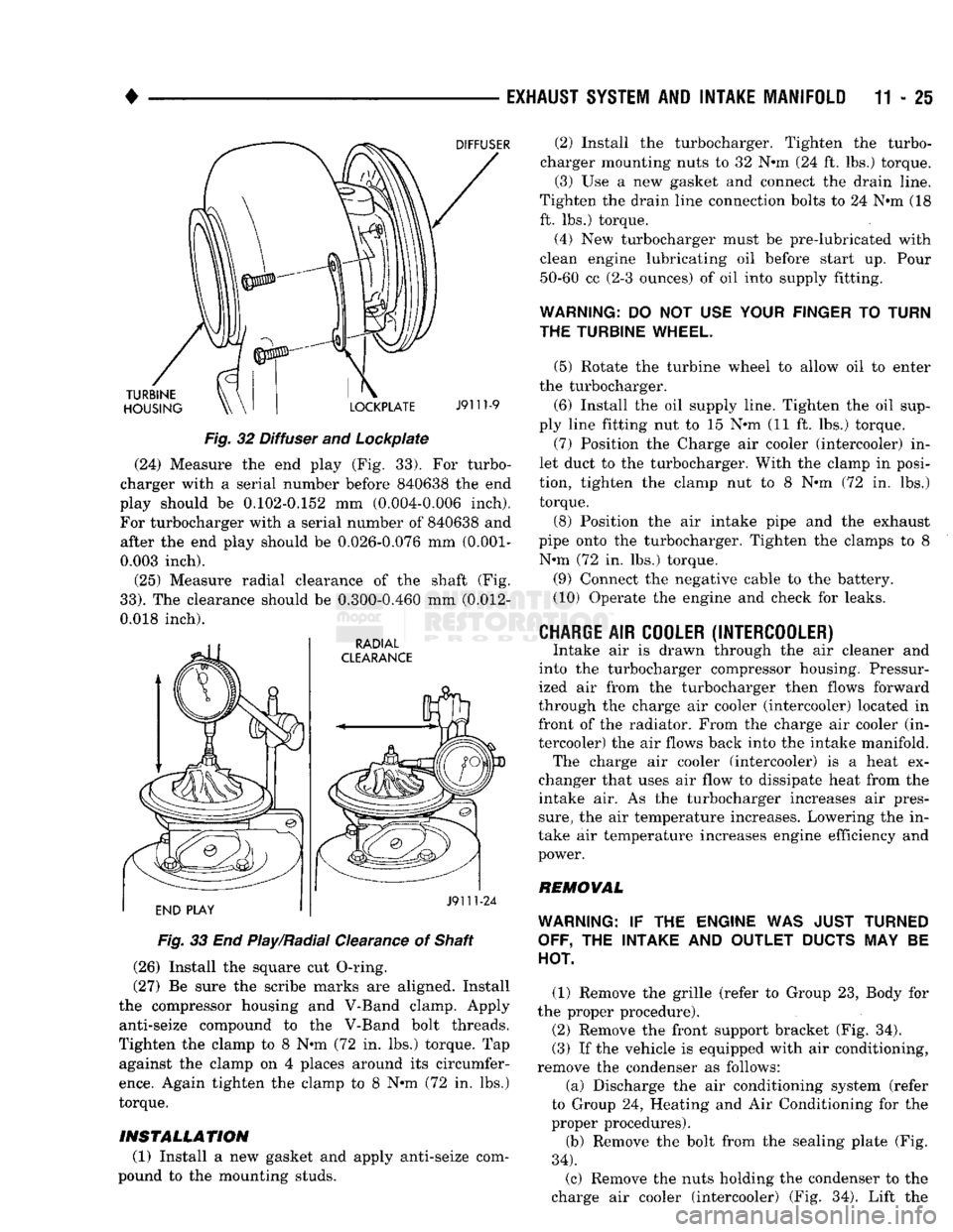
(25) Measure radial clearance of the shaft (Fig.
33).
The clearance should be 0.300-0.460 mm (0.012-
0.018 inch).
Fig.
33 End Play/Radial Clearance of Shaft
(26) Install the square cut O-ring.
(27) Be sure the scribe marks are aligned. Install
the compressor housing and V-Band clamp. Apply anti-seize compound to the V-Band bolt threads.
Tighten the clamp to 8 N-m (72 in. lbs.) torque. Tap against the clamp on 4 places around its circumfer
ence.
Again tighten the clamp to 8 N-m (72 in. lbs.)
torque.
INSTALLATION
(1) Install a new gasket and apply anti-seize com
pound to the mounting studs. (2) Install the turbocharger. Tighten the turbo
charger mounting nuts to 32 N-m (24 ft. lbs.) torque. (3) Use a new gasket and connect the drain line.
Tighten the drain line connection bolts to 24 N-m (18
ft. lbs.) torque.
(4) New turbocharger must be pre-lubricated with
clean engine lubricating oil before start up. Pour 50-60 cc (2-3 ounces) of oil into supply fitting.
WARNING:
DO NOT USE
YOUR FINGER
TO
TURN
THE TURBINE WHEEL.
(5) Rotate the turbine wheel to allow oil to enter
the turbocharger.
(6) Install the oil supply line. Tighten the oil sup
ply line fitting nut to 15 N-m (11 ft. lbs.) torque. (7) Position the Charge air cooler (intercooler) in
let duct to the turbocharger. With the clamp in posi
tion, tighten the clamp nut to 8 N-m (72 in. lbs.) torque.
(8) Position the air intake pipe and the exhaust
pipe onto the turbocharger. Tighten the clamps to 8 N-m (72 in. lbs.) torque.
(9) Connect the negative cable to the battery.
(10) Operate the engine and check for leaks.
CHARGE
AIR
COOLER (INTERCOOLER)
Intake air is drawn through the air cleaner and
into the turbocharger compressor housing. Pressur
ized air from the turbocharger then flows forward
through the charge air cooler (intercooler) located in front of the radiator. From the charge air cooler (in
tercooler) the air flows back into the intake manifold. The charge air cooler (intercooler) is a heat ex
changer that uses air flow to dissipate heat from the
intake air. As the turbocharger increases air pres
sure,
the air temperature increases. Lowering the in
take air temperature increases engine efficiency and
power.
REMOVAL
WARNING:
IF THE
ENGINE
WAS
JUST TURNED OFF,
THE
INTAKE
AND
OUTLET
DUCTS
MAY BE
HOT.
(1) Remove the grille (refer to Group 23, Body for
the proper procedure).
(2) Remove the front support bracket (Fig. 34).
(3) If the vehicle is equipped with air conditioning,
remove the condenser as follows:
(a) Discharge the air conditioning system (refer
to Group 24, Heating and Air Conditioning for the
proper procedures).
(b) Remove the bolt from the sealing plate (Fig.
34).
(c) Remove the nuts holding the condenser to the
charge air cooler (intercooler) (Fig. 34). Lift the