1993 DODGE TRUCK wheel bolt torque
[x] Cancel search: wheel bolt torquePage 160 of 1502
•
REAR
SUSPENSION
AND
AXLE
3 - 33
WHEEL BEARING SERVICE
REMOVAL (1) Remove the axle shaft, refer to the removal
procedure. (2) Remove the nut lock and adjustment nut.
(3) Remove the hub and drum assembly. The outer
wheel bearing will slide out as the hub is being re
moved. (4) Place hub on bench and remove inner grease
seal. Discard seal. (5) Remove inner wheel bearing. Inspect wheel
bearings for wear. Replace as necessary.
CLEANING AND INSPECTION (1) Thoroughly clean both wheel bearings and in
terior of the hub. Remove all of the residual lubri cant. (2) To clean the bearings:
• Soak them in an appropriate cleaning solvent
• Strike the flat of each bearing against a hardwood
block several times • Flush bearing between strikes
• Repeat the procedure above until each bearing is clean
• Dry the bearings with compressed air but do not
spin them (3) After cleaning, apply engine oil to each bear
ing. (4) Rotate each bearing slowly while applying
downward force. Examine the rollers for pitting and
roughness. Replace worn or otherwise defective bear
ings.
If a bearing has pitted and/or rough surfaced
rollers, replace both the bearing and bearing cup. (5) If reusable, remove the engine oil from each
bearing. Pack each bearing with multi-purpose
NLGI, grade 2, EP-type lubricant. Ensure that lubricant is forced into all the cav
ities between the bearing cage and rollers.
INSTALLATION (1) If a bearing and cup must be replaced, remove
the cup from the hub bore. Use a brass drift or an appropriate removal tool to tap out the cup. (2) Install the replacement bearing cup(s) with an
appropriate installation tool.
(3) Apply lubricant to surface area of the hub bore.
Install the inner wheel bearing in the hub. Install a
replacement bearing seal with an appropriate seal installation tool. (4) Inspect the bearing and seal contact surfaces on
the axle for burrs and/or roughness.
(5) Remove all the rough contact surfaces from the
axle.
Apply a coating of multi-purpose NLGI, grade
2,
EP-type lubricant to the axle.
CAUTION:
Use care to prevent the inner
wheel
bear
ing
and bearing
seal
from contacting the axle
threads
during installation. Otherwise, the
threads,
bearing,
and
seal
could
be
damaged.
(6) Carefully slide the hub onto the axle. Install
the outer wheel bearing, the locktab and outer wheel
bearing locknut.
(7) Tighten the adjustment nut to 163-190 Nnn
(120-140 ft. lbs.) torque while rotating the wheel. (8) Loosen the adjustment nut 1/3 of-a-turn (120
degrees) to provide 0.001-inch to 0.008-inch wheel
bearing end play.
(9) Tap the nut lock into the spindle keyway and
adjustment nut.
(10) Install the axle shaft, refer to the installation
procedure.
COMPLETE AXLE REMOVAL/INSTALLATION
REMOVAL It is not necessary to remove the complete axle
from the vehicle for routine or differential service. If
the differential housing or axle shaft tubes are dam aged, the complete axle can be removed and in
stalled.
(1) Raise the rear of the vehicle until the rear
wheels are not contacting the surface. Support the
vehicle body at the front of the rear springs.
(2) Use a wooden block to retain the brake pedal
in the up position.
(3) Remove the axle shafts, wheels, hubs and
brake drums. If necessary, refer to the applicable re moval procedures.
(4) Disconnect the brake line and cap the fittings
to prevent loss of brake fluid. (5) Disconnect the parking brake cables.
Scribe installation alignment reference marks
on drive shaft U-joint and on pinion yoke. (6) Disconnect the drive shaft U-joint from the pin
ion yoke. Secure it in an upright position to prevent
damage to the U-joint.
(7) Remove the rear shock absorbers and the rear
spring U-bolts from the axle. (8) Remove the rear axle from the vehicle.
INSTALLATION (1) If the differential housing cover was removed,
ensure differential housing and cover mating sur
faces are clean.
(2) If cover was removed, apply a bead of MOPAR
Silicone Rubber Sealant around the cover bolt circle.
Install the differential housing cover. Tighten the
cover bolts to 47 N»m (35 ft. lbs.) torque. Install the axle gear ratio identification tag under one of
the cover bolts.
(3) With the vehicle body supported at the front of
the rear springs, position the axle under the rear springs.
Page 161 of 1502
3
- 34
REAR SUSPENSION
AND
AXLE
• (4) Install the spring U-bolts and tighten the nuts
with the specified torque.
(5) Install the shock absorbers.
(6) Connect the parking brake cables.
(7) Connect the brake lines. Install the hubs and
brake drums. Adjust the wheel bearings (refer to Wheel Bearing Adjustment).
(8) Remove the block from the brake pedal. Bleed
and adjust the brakes.
(9) Connect the drive shaft to the pinion yoke with
the reference marks aligned. Tighten the U-joint clamp bolts to 21 N-m (16 ft. lbs./186 in. lbs.) torque.
(10) Install the rear wheels and tighten the lug
nuts with the specified torque (refer to Group 22,
Wheels And Tires). (11) Raise the rear of the vehicle, remove the sup
ports,
level the vehicle and position the supports. (12) Remove the fill hole plug from the differential
housing cover. Fill the differential housing to the correct level with MOPAR Hypoid Gear Lubricant, or
an equivalent product. Add 4 ounces of MOPAR Hypoid Gear Lubri
cant Additive for Trac-Lok equipped axles. (13) Install the fill hole plug. Remove the supports
and lower the vehicle. (14) Road test the vehicle to evaluate the results of
the repair.
DIFFERENTIAL
DISASSEMBLY
RE MO VA
L/DISA
SSEMBL Y
Remove the RWAL brake sensor
hold-down
bolt and pull the sensor from the differential
housing. The sensor must be removed to prevent damage when disassembling or assembling the differential components.
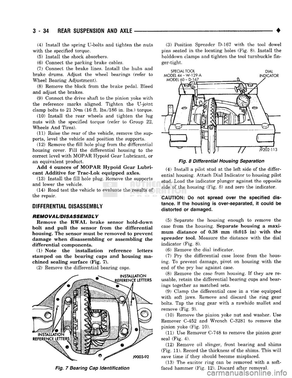
(1) Note the installation reference letters
stamped on the bearing caps and housing ma
chined sealing surface (Fig. 7). (2) Remove the differential bearing caps.
Fig.
7 Bearing Cap
identification
(3) Position Spreader D-167 with the tool dowel
pins seated in the locating holes (Fig. 8). Install the holddown clamps and tighten the tool turnbuckle fin
ger-tight.
SPECIAL TOOL DIAL
MODEL
44-W-129-A
INDICATOR
Fig.
8
Differential
Housing
Separation
(4) Install a pilot stud at the left side of the differ
ential housing. Attach Dial Indicator to housing pilot
stud. Load the indicator plunger against the opposite
side of the housing (Fig. 8) and zero the indicator.
CAUTION:
Do not
spread
over the specified
dis
tance. If the
housing
is over-separated, it
could
be distorted or
damaged.
(5) Separate the housing enough to remove the
case from the housing. Separate housing a maxi
mum distance of 0.38 mm (0.015 in) with the spreader tool. Measure the distance with the dial
indicator (Fig. 8).
(6) Remove the dial indicator. (7) Pry the differential case loose from the hous
ing. To prevent damage, pivot on housing with the
end of the pry bar against case.
(8) Remove the case from housing. If they are re
usable, retain the differential bearing cups and bear ings together as matched sets.
(9) Clamp the differential case in a vise equipped
with soft jaws. Remove and discard the ring gear
bolts.
Tap the ring gear with a rawhide mallet and
remove (Fig. 9).
(10) Remove the pinion yoke nut and washer. Use
Remover C-452 and Wrench C-3281 to remove the
pinion yoke (Fig. 10).
(11) Use Remover C-748 to remove the pinion gear
seal (Fig. 4).
(12) Remove oil slinger, front bearing and shims
(Fig. 11). Record the thickness of the shims. This will
save time if they should become misplaced.
(13) The excitor ring can be removed with a soft-
faced hammer (Fig. 12). Discard after removal.
Page 213 of 1502
5
- 26
BRAKES
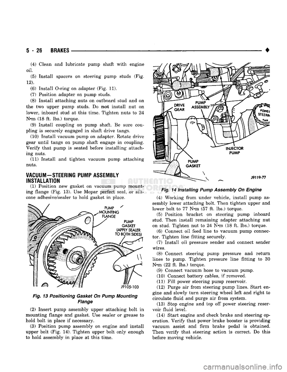
Fig. 13 Positioning Gasket On Pump Mounting
Flange
(2) Insert pump assembly upper attaching bolt in
mounting flange and gasket. Use sealer or grease to
hold bolt in place if necessary.
(3) Position pump assembly on engine and install
upper bolt (Fig. 14). Tighten upper bolt only enough
to hold assembly in place at this time. •
Fig. 14 Installing Pump Assembly On Engine (4) Working from under vehicle, install pump as
sembly lower attaching bolt. Then tighten upper and
lower bolt to 77 N»m (57 ft. lbs.) torque. (5) Position bracket on steering pump inboard
stud. Then install remaining adapter attaching nut
on stud. Tighten nut to 24 N«m (18 ft. lbs.) torque.
(6) Connect oil feed line to vacuum pump connec
tor. Tighten line fitting securely.
(7) Install oil pressure sender and connect sender
wires.
(8) Connect steering pump pressure and return
lines to pump. Tighten pressure line fitting to 30
N-m (22 ft. lbs.) torque.
(9) Connect vacuum hose to vacuum pump.
(10) Connect battery cables, if removed.
(11) Fill power steering pump reservoir.
(12) Purge air from steering pump lines. Start en
gine and slowly turn steering wheel left and right to circulate fluid and purge air from system.
(13) Stop engine and top off power steering reser
voir fluid level.
(14) Start engine and check brake and steering op
eration. Verify that power brake booster is providing
vacuum assist and firm brake pedal is obtained.
Then verify that steering action is correct. Do this
before moving vehicle.
(4) Clean and lubricate pump shaft with engine
oil.
(5) Install spacers on steering pump studs (Fig.
12).
(6) Install O-ring on adapter (Fig. 11).
(7) Position adapter on pump studs.
(8) Install attaching nuts on outboard stud and on
the two upper pump studs. Do not install nut on
lower, inboard stud at this time. Tighten nuts to 24
N-m (18 ft. lbs.) torque. (9) Install coupling on pump shaft. Be sure cou
pling is securely engaged in shaft drive tangs. (10) Install vacuum pump on adapter. Rotate drive
gear until tangs on pump shaft engage in coupling.
Verify that pump is seated before installing attach
ing nuts. (11) Install and tighten vacuum pump attaching
nuts.
VACUUM-STEERING PUMP ASSEMBLY INSTALLATION
(1) Position new gasket on vacuum pump mount
ing flange (Fig. 13). Use Mopar perfect seal, or sili
cone adhesive/sealer to hold gasket in place.
Page 216 of 1502
•
BRAKES
5 - 29 presses the outboard shoe lining against the opposite
side of the rotor to complete braking action.
The application or release of fluid pressure causes
only a very slight movement of the caliper and pis
ton. At brake release, the piston and caliper return
to the non-applied position.
The brakeshoes do not retract an appreciable dis
tance from the rotor. The minimal running clearance
between the lining and rotor provides improved re sponse and reduced pedal travel. It also helps in pre
venting dirt and foreign material from lodging
between the shoe and rotor surfaces.
DISC
BRAKE
LINING WEAR COMPENSATION
Normal lining wear is compensated for by extension
of the caliper piston and by lateral movement of the cal
iper in the adapter. Piston position is also determined
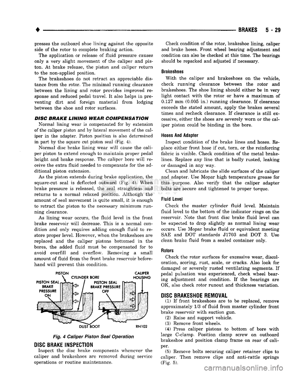
in part by the square cut piston seal (Fig. 4).
Normal disc brake lining wear will cause the cali
per piston to extend enough to maintain proper pedal height and brake response. The caliper bore will receive the extra fluid needed to compensate for the ad
ditional piston extension.
As the piston extends during brake application, the
square-cut seal is deflected outward (Fig. 4). When
brake pressure is released, the seal straightens and
returns to a normal relaxed position. Although the amount of seal movement is quite small, it is enough
to retract the piston to the necessary minimum run
ning clearance.
As lining wear occurs, the fluid level in the front
brake reservoir will decrease. This is a normal con dition and only requires adding enough fluid to restore proper level. However, when the brakeshoes are
replaced and the caliper pistons bottomed in the
bores,
the added fluid must be compensated for to avoid overfill and overflow. Removing a small
amount of fluid from the front brake reservoir before
hand will prevent this condition.
PISTON CALIPER
DUST BOOT
RN102
Fig.
4 Caliper
Piston
Seal
Operation
DISC
BRAKE INSPECTION
Inspect the disc brake components whenever the
caliper and brakeshoes are removed during service
operations or routine maintenance. Check condition of the rotor, brakeshoe lining, caliper
and brake hoses. Front wheel bearing adjustment and
condition can also be checked at this time. The bearings
should be repacked and adjusted if necessary.
Brakeshoes
With the caliper and brakeshoes on the vehicle,
check running clearance between the rotor and
brakeshoes. The shoe lining should either be in very light contact with the rotor or have a maximum of
0.127 mm (0.005 in.) running clearance. If clearance
exceeds the stated amount, apply the brakes several
times and recheck clearance. If clearance is still ex cessive, either the shoes are severely worn or the cal
iper piston could be binding in the bore.
Hoses
And Adapter Inspect condition of the brake lines and hoses. Re
place either front hose if cut, torn, or the reinforcing
fabric is visible. Check condition of the metal brake-
lines.
Replace any line that is badly rusted, leaking
or damaged in any way.
Clean and lubricate the slide surfaces of the caliper
and adapter. Use Mopar high temperature grease for
this purpose. Also verify that the caliper adapter
bolts are secure and tightened to proper torque.
Fluid Level Check the master cylinder fluid level. Maintain
fluid level to the bottom of the indicator rings on the
reservoir. Note that front disc brake fluid level can
be expected to drop slightly as normal lining wear occurs. Use Mopar brake fluid or equivalent meeting SAE and DOT standards J1703 and DOT 3. Use
clean brake fluid from a sealed container only.
Rotors
Check the rotor surfaces for excessive wear, discol
oration, scoring, rust, scale, or cracks. Also look for
damaged or severely rusted ventilating segments. If
pedal pulsation was experienced, check wheel bear ing adjustment and condition. If the bearings are OK, also check rotor runout and thickness variation.
DISC
BRAKESHOE
REMOVAL
(1) If front brakeshoes are to be replaced, remove
approximately 1/3 of fluid from master cylinder front
brake reservoir with suction gun. (2) Raise and support vehicle.
(3) Remove front wheels.
(4) Press caliper pistons to bottom of bore with
large C-clamp. Position clamp screw on outboard
brakeshoe and position clamp frame on rear of cali
per. (5) Remove bolts securing caliper retainer clips to
caliper. Then remove clips and anti-rattle springs (Fig. 5).
Page 221 of 1502
5
- 34
BRAKES
•
boot
>TALLir TOOL
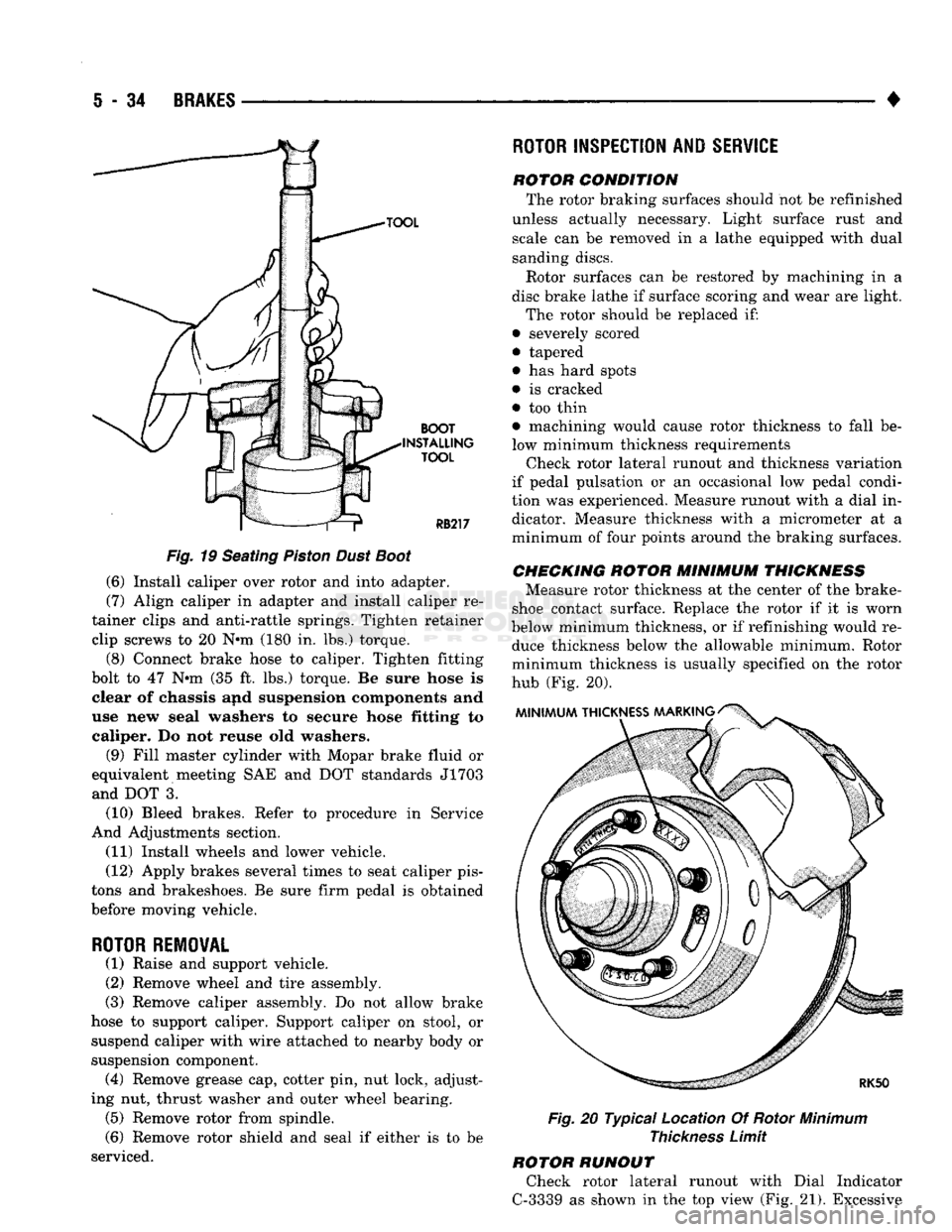
Fig.
19 Seating
Piston
Dust
Boot
(6) Install caliper over rotor and into adapter.
(7) Align caliper in adapter and install caliper re
tainer clips and anti-rattle springs. Tighten retainer clip screws to 20 N*m (180 in. lbs.) torque.
(8) Connect brake hose to caliper. Tighten fitting
bolt to 47 N»m (35 ft. lbs.) torque. Be sure hose is clear of chassis and suspension components and
use new seal washers to secure hose fitting to caliper. Do not reuse old washers.
(9) Fill master cylinder with Mopar brake fluid or
equivalent meeting SAE and DOT standards J1703 and DOT 3.
(10) Bleed brakes. Refer to procedure in Service
And Adjustments section.
(11) Install wheels and lower vehicle.
(12) Apply brakes several times to seat caliper pis
tons and brakeshoes. Be sure firm pedal is obtained
before moving vehicle.
ROTOR REMOVAL
(1) Raise and support vehicle.
(2) Remove wheel and tire assembly.
(3) Remove caliper assembly. Do not allow brake
hose to support caliper. Support caliper on stool, or suspend caliper with wire attached to nearby body or
suspension component. (4) Remove grease cap, cotter pin, nut lock, adjust
ing nut, thrust washer and outer wheel bearing. (5) Remove rotor from spindle.
(6) Remove rotor shield and seal if either is to be
serviced.
ROTOR
INSPECTION AND
SERVICE
rotor condition The rotor braking surfaces should not be refinished
unless actually necessary. Light surface rust and scale can be removed in a lathe equipped with dual
sanding discs.
Rotor surfaces can be restored by machining in a
disc brake lathe if surface scoring and wear are light.
The rotor should be replaced if:
• severely scored
• tapered
• has hard spots
• is cracked
• too thin • machining would cause rotor thickness to fall be
low minimum thickness requirements Check rotor lateral runout and thickness variation
if pedal pulsation or an occasional low pedal condi
tion was experienced. Measure runout with a dial in dicator. Measure thickness with a micrometer at a
minimum of four points around the braking surfaces.
CHECKING
ROTOR
MINIMUM
THICKNESS
Measure rotor thickness at the center of the brake-
shoe contact surface. Replace the rotor if it is worn
below minimum thickness, or if refinishing would re duce thickness below the allowable minimum. Rotor
minimum thickness is usually specified on the rotor
hub (Fig. 20).
Fig.
20 Typical Location Of Rotor
Minimum
Thickness
Limit
ROTOR RUNOUT Check rotor lateral runout with Dial Indicator
C-3339 as shown in the top view (Fig. 21). Excessive
Page 226 of 1502
BRAKES
5 - 39
DISC BRAKE LINING WEAR COMPENSATION
Normal lining wear is compensated for by exten
sion of the caliper piston and by lateral movement of
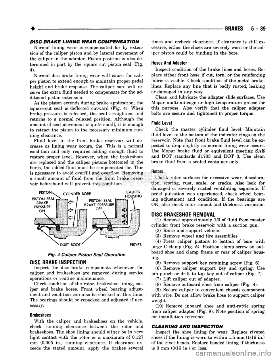
the caliper in the adapter. Piston position is also de termined in part by the square cut piston seal (Fig.
4).
Normal disc brake lining wear will cause the cali
per piston to extend enough to maintain proper pedal height and brake response. The caliper bore will receive the extra fluid needed to compensate for the ad
ditional piston extension.
As the piston extends during brake application, the
square-cut seal is deflected outward (Fig. 4). When
brake pressure is released, the seal straightens and returns to a normal relaxed position. Although the amount of seal movement is quite small, it is enough
to retract the piston to the necessary minimum run ning clearance. Fluid level in the front brake reservoir will de
crease as lining wear occurs, the. This is a normal
condition and only requires adding enough fluid to
restore proper level. However, when the brakeshoes are replaced and the caliper pistons bottomed in the
bores,
the added fluid must be compensated for. This is necessary to avoid overfill and overflow. Removing a small amount of fluid from the front brake reser
voir beforehand will prevent this condition.
Fig.
4 Caliper
Piston
Seal
Operation
DISC
BRAKE INSPECTION
Inspect the disc brake components whenever the
caliper and brakeshoes are removed during service
operations or routine maintenance. Check condition of the rotor, brakeshoe lining, cal
iper and brake hoses. Front wheel bearing adjust
ment and condition can also be checked at this time.
The bearings should be repacked and adjusted if nec essary.
Brakeshoes
With the caliper and brakeshoes on the vehicle,
check running clearance between the rotor and
brakeshoes. The shoe lining should either be in very light contact with the rotor or a maximum of 0.127
mm (0.005 in.) running clearance. If clearance exceeds the stated amount, apply the brakes several times and recheck clearance. If clearance is still ex
cessive, either the shoes are severely worn or the cal
iper piston could be binding in the bore.
Hoses
And Adapter Inspect condition of the brake lines and hoses. Re
place either front hose if cut, torn, or the reinforcing
fabric is visible. Check condition of the metal brake-
lines.
Replace any line that is badly rusted, leaking
or damaged in any way.
Clean and lubricate the adapter slide surfaces. Use
Mopar multi-mileage or high temperature grease for
this purpose. Also verify that the caliper adapter
bolts are secure and tightened to proper torque.
Fluid Level Check the master cylinder fluid level. Maintain
fluid level to the bottom of the indicator rings on the
reservoir. Note that front brake fluid level can be ex
pected to drop slightly as normal lining wear occurs.
Use Mopar brake fluid or equivalent meeting SAE and DOT standards J1703 and DOT 3. Use clean
brake fluid from a sealed container only.
Rotors
Check rotor surfaces for excessive wear, discolora
tion, scoring, rust, scale, or cracks. Also look for damaged or severely rusted ventilating segments. If
pedal pulsation was experienced, check wheel bear ing adjustment and condition. If the bearings are OK, also check rotor runout and thickness variation.
DISC
BRAKESHOE REMOVAL
(1) Remove approximately 1/3 of fluid from master
cylinder front brake reservoir with a suction gun. (2) Raise and support vehicle.
(3) Remove wheel and tire assemblies.
(4) Press caliper pistons to bottom of bore with
large C-clamp (Fig. 5). Position clamp screw on out
board shoe and clamp frame or rear of caliper hous ing. (5) Remove support key retaining screw (Fig. 6).
(6) Remove caliper support key and spring. Use
pin punch or drift to tap key out of caliper (Fig. 7). (7) Lift caliper out of adapter. (8) Remove outboard shoe from caliper (Fig. 8).
(9) Secure caliper to convenient chassis component
with wire. Do not allow brake hose to support caliper weight. (10) Remove inboard shoe and anti-rattle spring
from caliper adapter (Fig. 9). Note position of spring
for installation reference.
CLEANING AND INSPECTION Inspect the shoe lining for wear. Replace riveted
shoes if the lining is worn to within 1.5 mm (1/16 in.)
of the rivet heads. Replace bonded lining if thickness is 3 mm (3/16 in.) or less.
Page 251 of 1502
5
- 64
BRAKES
•
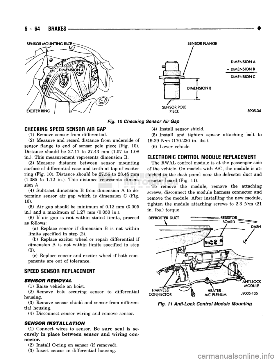
Fig.
10
Checking
CHECKING SPEED SENSOR
AIR GAP (1) Remove sensor from differential.
(2) Measure and record distance from underside of
sensor flange to end of sensor pole piece (Fig. 10).
Distance should be 27.17 to 27.43 mm (1.07 to 1.08
in.).
This measurement represents dimension B.
(3) Measure distance between sensor mounting
surface of differential case and teeth at top of exciter
ring (Fig. 10). Distance should be 27.56 to 28.45 mm (1.085 to 1.12 in,). This distance represents dimen
sion A.
(4) Subtract dimension B from dimension A to de
termine sensor air gap which is dimension C (Fig.
10).
(5) Air gap should be minimum of 0.12 mm (0.005
in.) and a maximum of 1.27 mm (0.050 in.). (6) If air gap is not within stated limits, proceed
as follows: (a) Replace sensor if dimension B is not within
limits specified in step (2). (b) Replace exciter wheel or repair differential if
dimension A is not within limits specified in step
(3).
(c) Replace sensor and exciter wheel if both com
ponents are out of tolerance.
SPEED
SENSOR REPLACEMENT
SENSOR
REMOVAL
(1) Raise vehicle on hoist.
(2) Remove bolt securing sensor to differential
housing.
(3) Remove sensor shield and sensor from differen
tial housing. (4) Disconnect sensor wiring and remove sensor.
SENSOR
INSTALLATION
(1) Connect wires to sensor. Be sure seal is se
curely in place between sensor and wiring con
nector. (2) Install O-ring on sensor (if removed). (3) Insert sensor in differential housing.
SENSOR
FLANGE
DIMENSION A
-
DIMENSION
B
DIMENSION C
SENSOR
POLE
PIECE
8905-34
Sensor
Air Gap (4) Install sensor shield.
(5) Install and tighten sensor attaching bolt to
19-29 Nnn (170-230 in. lbs.).
(6) Lower vehicle.
ELECTRONIC CONTROL MODULE REPLACEMENT
The RWAL control module is at the passenger side
of the vehicle. On models with A/C, the module is at
tached to the dash panel near the defroster duct and
resistor board (Fig. 11). To remove the module, remove the attaching
screws, disconnect the module harness connector and
remove the module. After installing the new module,
tighten the module attaching screws to 2.3 N»m (21 in. lbs.) torque.
Fig.
11
Anti-Lock
Control
Module
Mounting
Page 252 of 1502
•
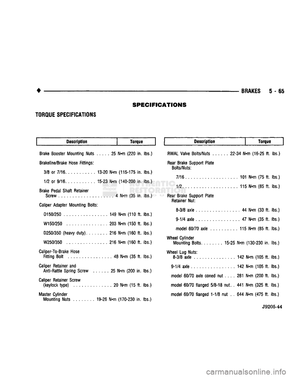
SPECIFICATIONS
BRAKES
5 - 65
Description
Torque Description
Torque
Brake Booster Mounting Nuts 25 N«m (220 in. lbs.)
Brakeline/Brake Hose Fittings: 3/8 or 7/16 13-20 Nrn
(115-175
in. lbs.) 1/2 or 9/16 15-23 N«m
(140-200
in. lbs.)
Brake Pedal Shaft Retainer Screw 4 Ntn (35 in. lbs.)
Caliper Adapter Mounting
Bolts:
D150/250
149 N«m (110 ft. lbs.)
W150/250
203 N«m (150 ft. lbs.)
D250/350
(heavy
duty)
216 Nrn (160 ft. lbs.)
W250/350
216 N»m (160 ft. lbs.)
Caliper-To-Brake Hose
Fitting
Bolt 48 N«m (35 ft. lbs.)
Caliper Retainer and Anti-Rattle Spring Screw 25 N«m (200 in. lbs.)
Caliper Retainer Screw (keylock
type)
20 N«m (15 ft. lbs.)
Master Cylinder Mounting Nuts 19-26 N«m
(170-230
in. lbs.)
RWAL
Valve Bolts/Nuts
22-34
Nrn
(16-25
ft. lbs.)
Rear Brake Support Plate
Bolts/Nuts:
7/16 101 N»m (75 ft. lbs.)
1/2 115 N«m (85 ft. lbs.)
Rear Brake Support Plate Retainer Nut:
8-3/8
axle
44 N«m (33 ft. lbs.)
9-1/4
axle
47 N-m (35 ft. lbs.) model
60/70
axle
115 N-m (85 ft. lbs.)
Wheel
Cylinder Mounting Bolts 15-25 N«m
(130-230
in. lbs.)
Wheel
Lug Nuts: 8-3/8
axle
142 N»m (105 ft. lbs.)
9-1/4
axle
142 Nrn (105 ft. lbs.) model
60/70
axle
coned nut 281 N«m (200 ft. lbs.)
model
60/70
flanged
5/8-18
nut. . 441 Nrn (325 ft. lbs.)
model
60/70
flanged 1-1/8 nut . . 644 Nrn (475 ft. lbs.)
J9205-44
TORQUE
SPECIFICATIONS