1993 DODGE TRUCK fuel type
[x] Cancel search: fuel typePage 902 of 1502

•
FUEL SYSTEM
14 - 83 below minimum value or above maximum value. The
PCM stores a DTC when these conditions occur.
WATER-IN-FUEL LAMP-PCM
OUTPUT
The water-in-fuel lamp is turned on and off by the
PCM. The lamp is turned on by the PCM when it re ceives an input from the water-in-fuel sensor. The sensor sends an input to the PCM when it detects
water in the fuel/water separator filter.
FUEL DRAIN MANIFOLD
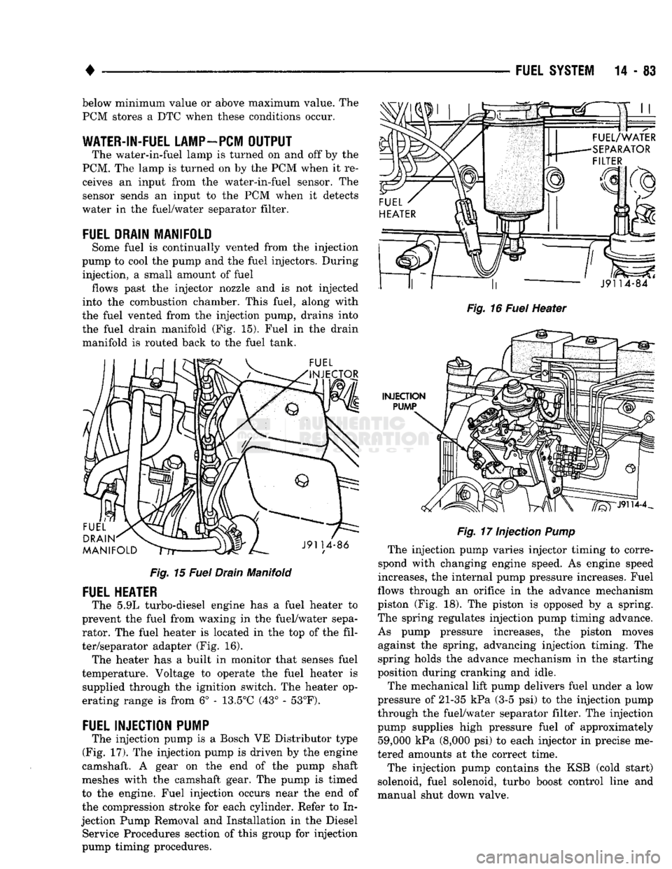
Some fuel is continually vented from the injection
pump to cool the pump and the fuel injectors. During injection, a small amount of fuel flows past the injector nozzle and is not injected
into the combustion chamber. This fuel, along with
the fuel vented from the injection pump, drains into
the fuel drain manifold (Fig. 15). Fuel in the drain manifold is routed back to the fuel tank.
Fig.
15
Fuel
Drain Manifold
FUEL
HEATER
The 5.9L turbo-diesel engine has a fuel heater to
prevent the fuel from waxing in the fuel/water sepa rator. The fuel heater is located in the top of the fil
ter/separator adapter (Fig. 16). The heater has a built in monitor that senses fuel
temperature. Voltage to operate the fuel heater is supplied through the ignition switch. The heater op
erating range is from 6° - 13.5°C (43° - 53°F).
FUEL
INJECTION PUiVSP
The injection pump is a Bosch VE Distributor type
(Fig. 17). The injection pump is driven by the engine
camshaft. A gear on the end of the pump shaft
meshes with the camshaft gear. The pump is timed
to the engine. Fuel injection occurs near the end of the compression stroke for each cylinder. Refer to In
jection Pump Removal and Installation in the Diesel Service Procedures section of this group for injection
pump timing procedures.
Fig.
16
Fuel
Heater
Fig.
17 Injection
Pump
The injection pump varies injector timing to corre
spond with changing engine speed. As engine speed
increases, the internal pump pressure increases. Fuel
flows through an orifice in the advance mechanism
piston (Fig. 18). The piston is opposed by a spring.
The spring regulates injection pump timing advance.
As pump pressure increases, the piston moves against the spring, advancing injection timing. The
spring holds the advance mechanism in the starting
position during cranking and idle.
The mechanical lift pump delivers fuel under a low
pressure of 21-35 kPa (3-5 psi) to the injection pump
through the fuel/water separator filter. The injection
pump supplies high pressure fuel of approximately 59,000 kPa (8,000 psi) to each injector in precise me
tered amounts at the correct time.
The injection pump contains the KSB (cold start)
solenoid, fuel solenoid, turbo boost control line and
manual shut down valve.
Page 1082 of 1502

•
AUTOMATIC
TRANSMISSION—32RH/36RH/37RH/42RH/46RH
21 - 81
TORQUE
CONVERTER
A three element torque converter
is
used
for all ap
plications.
The
converter consists
of the
impeller,
sta-
tor
and
turbine.
The
converter also contains
an
overrunning clutch
and a
modulated converter clutch
mechanism.
The converter used with
1993,
42RH transmissions
is
new. The
converter
hub was
changed
to
accept
the
new style drive flats
on the oil
pump inner gear.
The
new style converter
is not
interchangeable with pre
vious designs.
The converter modulated clutch consists
of a
slid
ing clutch piston, clutch springs
and the
clutch disc
friction material.
The
clutch provides optimum
torque transfer
and
economy when engaged.
The clutch disc
is
attached
to the
converter front
cover.
The
clutch piston
and
clutch springs
are at
tached
to the
turbine
hub. The
springs dampen
en
gine firing impulses
and
loads during
the
initial
phase
of
converter clutch engagement.
Clutch engagement
is
controlled
by the
converter
clutch valve
and
solenoid. Both
are
located
on the
transmission valve body. Clutch engagement occurs in drive range
at
speeds above approximately 30-35
mph.
The clutch provides reduced engine speed
and
greater fuel economy when engaged. Clutch engage
ment also provides reduced transmission fluid tem
peratures.
COMPONENTS
UNIQUE
TO
DIESEL VERSION
OF
46RH
Planetary
Gears
The transmission
and
overdrive planetary gear car
riers
in the
diesel version
of the
46RH
are
heavy duty components.
The
transmission planetary carriers have four pinion gears.
The
carrier
in the
over
drive compounder
has
five pinion gears.
The
heavy
duty planetary units
are
unique
to the
diesel 46RH.
Clutch
Packs
Clutch packs used
in the
diesel version
of the
46RH contain
the
following number
of
discs
and
plates:
• transmission front/rear clutch
has 4
discs
and 5
steel plates
• overdrive clutch
has 5
discs
and 6
steel plates
• overdrive direct clutch
has 8
discs
and 9
steel
plates
Governor
Weight
Assembly
The governor weight assembly
in the
diesel 46RH
is made
of
alloyed brass.
The
diesel weight assembly
is easily identified
by the
distinctive gold color
of the
alloyed material.
The
heavier weight assembly pro
vides
the
shift points needed
to
offset lower operating speeds
of a
diesel engine. The alloyed weight assembly
is
unique
to the
diesel
46RH.
It is not
interchangeable with
the
weight
as
semblies used
in gas
engine versions.
Diesel
Thermo
Switch
Fourth gear operation
in the
diesel 46RH
is
also
controlled
by two
temperature sensitive thermo- switches.
The first thermo-switch
is the
engine coolant tem
perature switch. This switch prevents overdrive fourth gear operation when engine coolant tempera
ture
is
below approximately
65° F.
The second thermo-switch directly monitors trans
mission fluid temperature.
The
switch will either
downshift
the
transmission
to
third gear,
or
prevent a
3-4
upshift when fluid temperature exceeds
270-275°
F.
The fluid temperature switch
is
located
in a
boss
built into
the
cooler outlet line.
The
boss
and
switch are located approximately
2-3
inches from
the
outlet
line fitting
in the
transmission case.
The engine coolant
and
fluid temperature switches
are
in
circuit with
the
overdrive control switch
in the
instrument panel.
GEAR RATIOS
42RH forward gear ratios
are:
First gear
=
2.74:1
Second gear
= 1.54:1
Third gear
= 1.00:1
Fourth gear
=
0.69:1.
46RH forward gear ratios
are:
First gear
=
2.45:1 Second gear
= 1.45:1
Third gear
= 1.00:1
Fourth gear
=
0.69:1.
RECOMMENDED
FLUID
The recommended
and
preferred fluid
for
42RH/
46RH transmissions
is
Mopar
ATF
Plus, type
7176.
Use Mopar Dexron
II
only when
ATF
Plus
is not
readily available.
TRANSMISSION
IDENTIFICATION
The transmission part
and
identification numbers
and codes
are
stamped
on the
left side
of the
case
just above
the oil pan
gasket surface
(Fig. 3).
The first letter/number group
is the
assembly part
number.
The
next number group
the
transmission
build date.
The
last number group
is the
transmis sion serial number. Refer
to
this information when
ordering replacement parts.
FOURTH
GEAR OVERDRIVE COMPONENTS
42RH/46RH models have three transmission shafts.
An intermediate shaft
is
positioned between
the in
put
and
output shafts.
The
output shaft
is in the
Page 1371 of 1502

22 - 2
WHEELS
AND
TIRES
•
METRIC
TIRE
SIZES
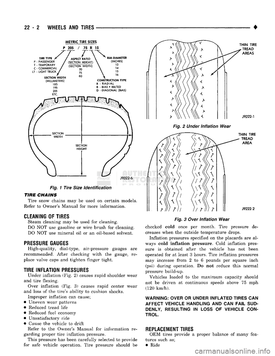
P
205 / 75 I 15
J9322-6
Fig.
1
Tire
Size
identification
TIRE
CHAINS
Tire snow chains may be used on certain models.
Refer to Owner's Manual for more information.
CLEANING
OF
TIRES
Steam cleaning may be used for cleaning.
DO NOT use gasoline or wire brush for cleaning.
DO NOT use mineral oil or an oil-based solvent.
PRESSURE GAUGES
High-quality, dial-type, air-pressure gauges are
recommended. After checking with the gauge, re
place valve caps and tighten finger tight.
TIRE
INFLATION
PRESSURES
Under inflation (Fig. 2) causes rapid shoulder wear
and tire flexing. Over inflation (Fig. 3) causes rapid center wear
and loss of the tire's ability to cushion shocks. Improper inflation can cause;
• Uneven wear patterns
• Reduced tread life
• Reduced fuel economy
• Unsatisfactory ride
• Cause the vehicle to drift Refer to the Owner's Manual for information re
garding proper tire inflation pressure. This pressure has been carefully selected to provide
for safe vehicle operation. Tire pressure should be
Fig.
2
Under
infiation
Wear
Fig.
3
Over
Infiation
Wear
checked cold once per month. Tire pressure de creases when the outside temperature drops.
Inflation pressures specified on the placards are al
ways cold
inflation
pressure. Cold inflation pres sure is obtained after the vehicle has not been
operated for at least 3 hours. Tire inflation pressures may increase from 2 to 6 pounds per square inch (psi) during operation. Do not reduce this normal
pressure build-up.
Vehicles loaded to the maximum capacity should
not be driven at continuous speeds above 75 mph (120 km/h).
WARNING: OVER
OR
UNDER INFLATED TIRES
CAN
AFFECT VEHICLE HANDLING
AND CAN
FAIL
SUD DENLY, RESULTING
IN
LOSS
OF
VEHICLE CON
TROL
REPLACEMENT TIRES
OEM tires provide a proper balance of many fea
tures such as; • Ride