1993 DODGE TRUCK fuel type
[x] Cancel search: fuel typePage 830 of 1502
•
FUEL SYSTEM
14-11 (3)
Install hoses
to
filter. Tighten clamps
to 1 N*m
(10 in. lbs.)
torque. (4) Lower vehicle.
(5)
Connect battery cable
to
battery.
(6) Start engine
and
check
for
leaks.
FUEL
FILTER—5.9L
GAS ENGINE
For diesel engines, refer
to
Fuel/Water Separator
Filter
in the
Diesel Fuel Injection—Service Proce
dures section
of
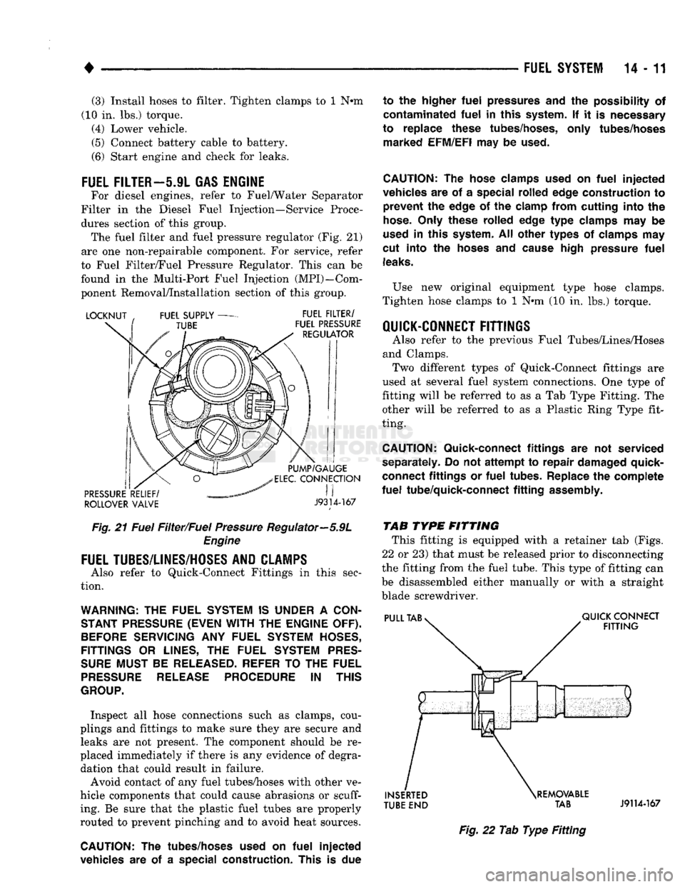
this group. The fuel filter
and
fuel pressure regulator
(Fig. 21)
are
one
non-repairable component.
For
service, refer
to Fuel Filter/Fuel Pressure Regulator. This
can be
found
in the
Multi-Port Fuel Injection (MPI)—Com
ponent Removal/Installation section
of
this group.
ROLLOVER VALVE
J9314-167
Fig.
21
Fuel Filter/Fuel Pressure Regulator—5.9L Engine
FUEL
TUBES/LINES/HOSES
AND CLAMPS
Also refer
to
Quick-Connect Fittings
in
this sec
tion.
WARNING:
THE
FUEL
SYSTEM
IS
UNDER
A
CON
STANT
PRESSURE
(EVEN WITH
THE
ENGINE
OFF).
BEFORE
SERVICING
ANY
FUEL
SYSTEM
HOSES,
FITTINGS
OR
LINES,
THE
FUEL
SYSTEM
PRES
SURE
MUST
BE
RELEASED-
REFER
TO
THE
FUEL
PRESSURE
RELEASE
PROCEDURE
IN
THIS
GROUP.
Inspect
all
hose connections such
as
clamps, cou
plings
and
fittings
to
make sure they
are
secure
and
leaks
are not
present.
The
component should
be re
placed immediately
if
there
is any
evidence
of
degra dation that could result
in
failure.
Avoid contact
of any
fuel tubes/hoses with other
ve
hicle components that could cause abrasions
or scuff
ing.
Be
sure that
the
plastic fuel tubes
are
properly
routed
to
prevent pinching
and to
avoid heat sources.
CAUTION:
The
tubes/hoses used
on
fuel
injected
vehicles
are of a
special construction. This
is due
to
the
higher
fuel
pressures
and the
possibility
of
contaminated
fuel
in
this system.
If it is
necessary
to replace these tubes/hoses, only tubes/hoses marked EFM/EFI
may
be
used.
CAUTION:
The
hose clamps used
on
fuel
injected
vehicles
are of a
special rolled edge construction
to
prevent
the
edge
of the
clamp from cutting into
the
hose.
Only these rolled edge
type
clamps
may be
used
in
this system.
All
other types
of
clamps
may
cut into
the
hoses
and
cause high pressure
fuel
leaks.
Use
new
original equipment type hose clamps.
Tighten hose clamps
to 1 N*m (10 in. lbs.)
torque.
QUICK-CONNECT FITTINGS
Also refer
to the
previous Fuel Tubes/Lines/Hoses
and Clamps. Two different types
of
Quick-Connect fittings
are
used
at
several fuel system connections.
One
type
of
fitting will
be
referred
to as a Tab
Type Fitting.
The
other will
be
referred
to as a
Plastic Ring Type fit
ting.
CAUTION:
Quick-connect fittings
are not
serviced
separately.
Do not
attempt
to
repair damaged quick-
connect fittings
or
fuel
tubes. Replace
the
complete
fuel
tube/quick-connect
fitting
assembly.
TAB
TYPE
FITTING This fitting
is
equipped with
a
retainer
tab
(Figs.
22
or
23) that must
be
released prior
to
disconnecting
the fitting from
the
fuel tube. This type
of
fitting
can
be disassembled either manually
or
with
a
straight
blade screwdriver.
TUBE
END TAB
J9114-167
Fig.
22 Tab
Type
Fitting
Page 832 of 1502
•
FUEL
SYSTEM
14 - 13 (1) Disconnect negative cable from the battery.
(2) Perform the Fuel Pressure Release Procedure.
Refer to the Fuel Pressure Release Procedure in this section.
(3) Bend the retainer tab downward.
CAUTION:
If the
retainer
tab on the
removable
pull
tab
is not
bent
down
prior
to
disconnecting
the
quick-connect
fitting,
the
connector
could
be
dam
aged.
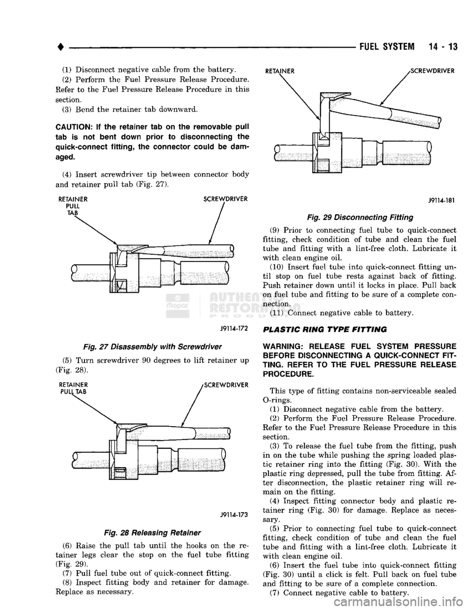
(4) Insert screwdriver tip between connector body
and retainer pull tab (Fig. 27).
RETAINER
SCREWDRIVER
J9114-172
J9114-181
Fig.
29
Disconnecting
Fitting
(9) Prior to connecting fuel tube to quick-connect
fitting, check condition of tube and clean the fuel
tube and fitting with a lint-free cloth. Lubricate it
with clean engine oil.
(10) Insert fuel tube into quick-connect fitting un
til stop on fuel tube rests against back of fitting.
Push retainer down until it locks in place. Pull back on fuel tube and fitting to be sure of a complete con
nection.
(11) Connect negative cable to battery.
PLASTIC RING TYPE FITTING
Fig.
27
Disassembly
with
Screwdriver
(5) Turn screwdriver 90 degrees to lift retainer up
(Fig. 28).
RETAINER
PULL
TAB
SCREWDRIVER
J9114-173
Fig.
28
Releasing
Retainer
(6) Raise the pull tab until the hooks on the re
tainer legs clear the stop on the fuel tube fitting
(Fig. 29). (7) Pull fuel tube out of quick-connect fitting.
(8) Inspect fitting body and retainer for damage.
Replace as necessary.
WARNING:
RELEASE
FUEL
SYSTEM PRESSURE
BEFORE
DISCONNECTING
A
QUICK-CONNECT FIT
TING.
REFER
TO THE
FUEL
PRESSURE RELEASE PROCEDURE.
This type of fitting contains non-serviceable sealed
O-rings. (1) Disconnect negative cable from the battery.
(2) Perform the Fuel Pressure Release Procedure.
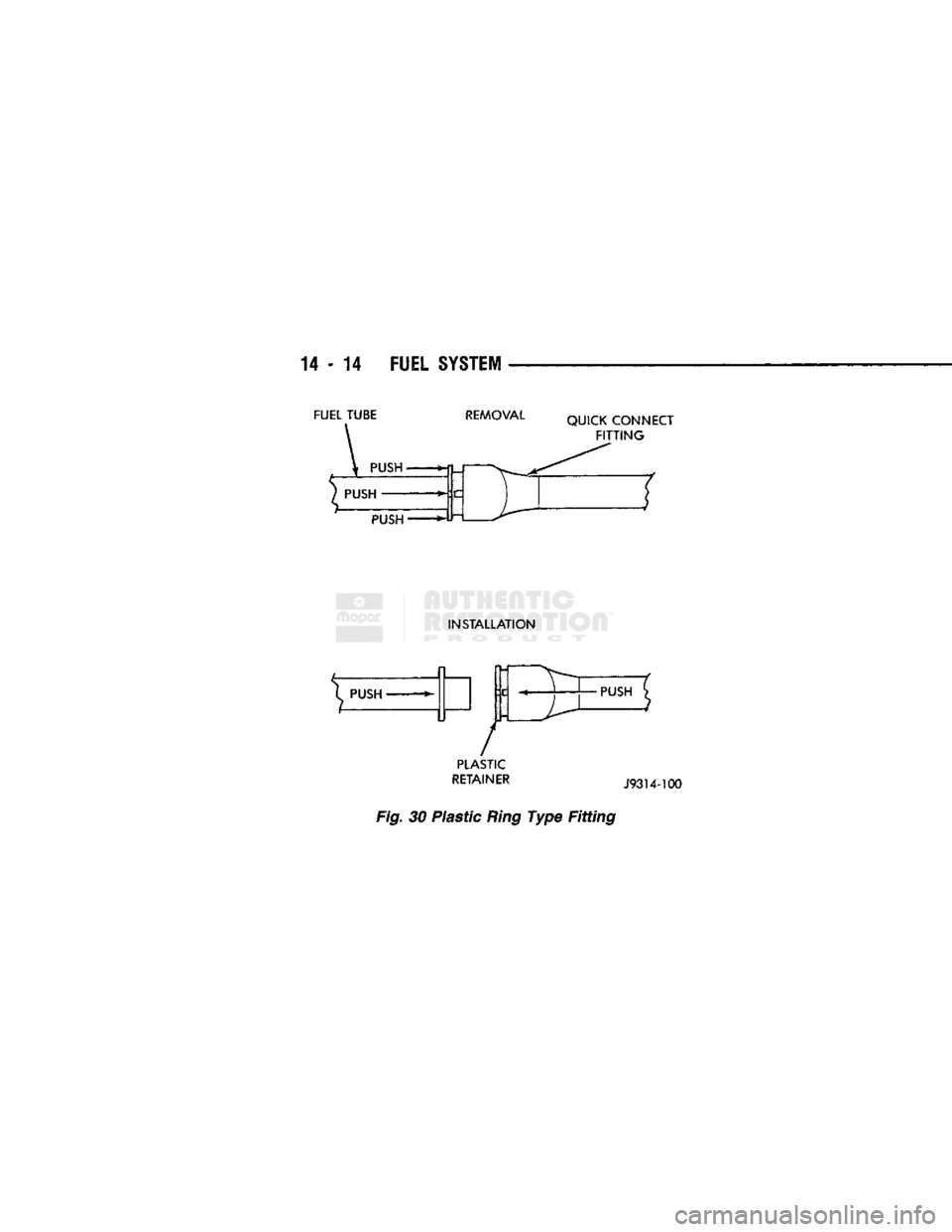
Refer to the Fuel Pressure Release Procedure in this section. (3) To release the fuel tube from the fitting, push
in on the tube while pushing the spring loaded plas
tic retainer ring into the fitting (Fig. 30). With the
plastic ring depressed, pull the tube from fitting. Af ter disconnection, the plastic retainer ring will re
main on the fitting.
(4) Inspect fitting connector body and plastic re
tainer ring (Fig. 30) for damage. Replace as neces sary.
(5) Prior to connecting fuel tube to quick-connect
fitting, check condition of tube and clean the fuel
tube and fitting with a lint-free cloth. Lubricate it
with clean engine oil.
(6) Insert the fuel tube into quick-connect fitting
(Fig. 30) until a click is felt. Pull back on fuel tube
and fitting to be sure of a complete connection.
(7) Connect negative cable to battery.
Page 833 of 1502
14 - 14
FUEL
SYSTEM
FUEL TUBE
REMOVAL
QUICK CONNECT
FITTING
PUSH
INSTALLATION
^ PUSH
»-
/
PLASTIC
RETAINER
J93U-100
Fig.
30 Plastic
Ring
Type Fitting
•PUSH
Page 839 of 1502
14-20 FUEL
SYSTEM
•
FUEL
TANKS
INDEX
page
Fuel Gauge Sending
Unit
24
Fuel Pump
22
Fuel Reservoir
23
Fuel Tank
Filler
Tube
Cap 20
Fuel Tank Pressure Relief/Rollover Valve
...... 24
GENERAL
INFORMATION
All Dodge Trucks pass a full 360 degree rollover with
out fuel leakage. To accomplish this, fuel and vapor
flow controls are required for all fuel tank connections. All models have a pressure relief/rollover valve
mounted in the top of the fuel tank. On vehicles equipped with a return line from fuel pump to fuel
tank, a one-way check valve is used to provide required
protection. In addition to the valve, improved flow con trol is used in the fuel pump. Fuel flow is controlled if
pump is subjected to higher than normal pressure dur ing rollover. For the same reason, a fuel tank filler tube
cap (gas cap) with higher pressure setting is used to
control fuel flow on vehicles with side fill. An evaporation control system is used to reduce
emissions of fuel vapors into atmosphere by evapora
tion and to reduce unburned hydrocarbons emitted
by vehicle engine. When fuel evaporates from fuel
tank, vapors pass through vent hoses or tubes to a
charcoal canister. The are temporarily held in the
canister. When the engine is running, the vapors are
drawn into intake manifold. Refer to Group 25,
Emission Control System for additional information. Inspect all hose connections to make sure they are
secure and not leaking. Hoses should be replaced im
mediately if there is any evidence of degradation
that could result in failure. Avoid contact with clamps or other components
that cause abrasions or scuffing. Be sure that the
rubber hoses are properly routed to prevent pinching and to avoid heat sources.
The hoses used on fuel injected vehicles are of a
special construction due to higher fuel pressures in
volved in system. If hoses need replacement, only use
hoses marked EFM/EFI.
The hose clamps used on fuel injected vehicles have
a special rolled edge construction. This prevents the
edge of the clamp from cutting into the hose. Only
these rolled edge type clamps may be used on this system. Other clamps may cut into the hoses. This
could cause high pressure fuel leaks.
NO-LEAD FUEL TANK FILLER TUBE
All catalyst equipped vehicles have a special fuel
tank filler tube. The fuel filler opening is smaller in
page
Fuel Tank Skid
Plate
. 20
Fuel Tanks
21
General
Information
20
Heat Shields
21
No-Lead
Fuel Tank
Filler
Tube
20
diameter than those used for non-catalyst vehicles to
permit entry of only the smaller no-lead fuel nozzles.
A deflector is installed in the fuel filler opening. The
deflector is opened by the no-lead fuel nozzle. The fuel filler tube on these models has a one-way
ball check valve. The valve is designed to prevent
fuel back splash which may occur while filling the tank. A label is attached to instrument panel under fuel
gauge that reads UNLEADED FUEL ONLY as a re
minder to driver. A similar label is located near fuel
tank filler.
FUEL TANK FILLER TUBE
CAP The loss of any fuel or vapor out of filler neck is
prevented by the use of a pressure-vacuum fuel tank
filler tube cap. Relief valves inside cap will release only under significant pressure of 6.58 to 8.44 kPa (1.95 to 2.5 psi). The vacuum release for all gas caps
is between .97 and 2.0 kPa (.14 and .29 psi). This cap
must be replaced by a similar unit if replacement is necessary. This is in order for the system to remain
effective.
CAUTION:
Remove
fuel
tank
filler
tube
cap
before
servicing
any
fuel
system component. This
is
done
to help
relieve
tank pressure.
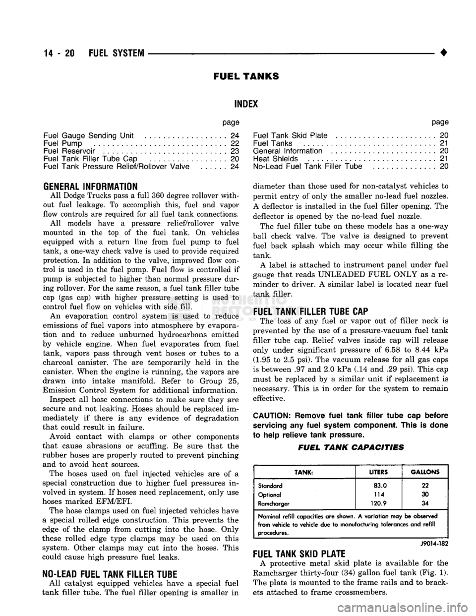
FUEL
TANK
CAPACITIES
TANK:
LITERS
GALLONS
Standard
83.0
22
Optional 114
30
Ramcharger 120.9 34
Nominal
refill
capacities are
shown.
A variation may be observed
from vehicle to vehicle due to manufacturing tolerances and
refill
procedures.
J9014-182
FUEL TANK SKID PLATE
A protective metal skid plate is available for the
Ramcharger thirty-four (34) gallon fuel tank (Fig. 1).
The plate is mounted to the frame rails and to brack ets attached to frame crossmembers.
Page 860 of 1502
•
FUEL
SYSTEM
14 - 41
THROTTLE
BODY
FUEL
RAIL
CONNECTING
HOSES
THROTTLE
BODY
MOUNTING
BOLTS
J9214-31
Fig.
18
Throttle
Body
MOUNTING
SCREWS
MAP
SENSOR
RUBBER
FITTING
J9314-87
Fig.
19 Air Control
Passage
FUEL
RAIL
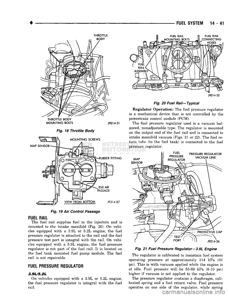
The fuel rail supplies fuel to the injectors and is
mounted to the intake manifold (Fig. 20). On vehi
cles equipped with a 3.9L or 5.2L engine, the fuel
pressure regulator is attached to the rail and the fuel
pressure test port is integral with the rail. On vehi cles equipped with a 5.9L engine, the fuel pressure
regulator is not part of the fuel rail. It is located on
the fuel tank mounted fuel pump module. The fuel
rail is not repairable.
FUEL
PRESSURE
REGULATOR
3.9L/5.2L On vehicles equipped with a 3.9L or 5.2L engine,
the fuel pressure regulator is integral with the fuel
rail.
J9214-32
Fig.
20
Fuel
Rail—Typical Regulator Operation: The fuel pressure regulator
is a mechanical device that is not controlled by the
powertrain control module (PCM).
The fuel pressure regulator used is a vacuum bal
anced, nonadjustable type. The regulator is mounted
on the output end of the fuel rail and is connected to
intake manifold vacuum (Figs. 21 or 22). The fuel re
turn tube (to the fuel tank) is connected to the fuel
pressure regulator.
MAP
SENSOR
docc EL
PRESSURE
REGULATOR
„
VACUUM
LINE
REGULATOR
PROTECTIVE
CAP
J9214-26
Fig.
21
Fuel
Pressure
Regulator—3.9L
Engine
The regulator is calibrated to maintain fuel system
operating pressure at approximately 214 kPa (31
psi).
This is with vacuum applied while the engine is at idle. Fuel pressure will be 55-69 kPa (8-10 psi)
higher if vacuum is not applied to the regulator.
The pressure regulator contains a diaphragm, cali
brated spring and a fuel return valve. Fuel pressure operates on one side of the regulator, while spring
Page 871 of 1502
14-52
FUEL
SYSTEM
•
CAMSHAFT
POSITION
SENSOR
TESTING
Refer to Group 8D, Ignition Systems for testing.
COOLANT
TEMPERATURE
SENSOR
TEST
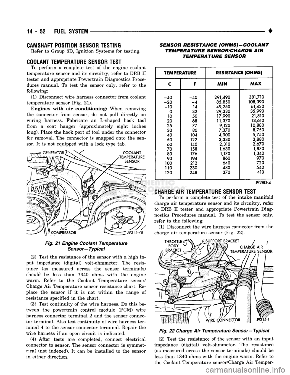
To perform a complete test of the engine coolant
temperature sensor and its circuitry, refer to DRB II
tester and appropriate Powertrain Diagnostics Proce
dures manual. To test the sensor only, refer to the
following: (1) Disconnect wire harness connector from coolant
temperature sensor (Fig. 21). Engines with air conditioning; When removing
the connector from sensor, do not pull directly on
wiring harness. Fabricate an L-shaped hook tool
from a coat hanger (approximately eight inches
long).
Place the hook part of tool under the connector
for removal. The connector is snapped onto the sen sor. It is not equipped with a lock type tab.
Fig.
21
Engine
Coolant
Temperature
Sensor—
Typical
(2) Test the resistance of the sensor with a high in
put impedance (digital) volt-ohmmeter. The resis
tance (as measured across the sensor terminals) should be less than 1340 ohms with the engine
warm. Refer to the Coolant Temperature sensor/ Charge Air Temperature sensor resistance chart. Re
place the sensor if it is not within the range of resistance specified in the chart.
(3) Test continuity of the wire harness. Do this be
tween the powertrain control module (PCM) wire
harness connector terminal 2 and the sensor connec
tor terminal. Also test continuity of wire harness ter
minal 4 to the sensor connector terminal. Repair the
wire harness if an open circuit is indicated.
(4) After tests are completed, connect electrical
connector to sensor. The sensor connector is symmet
rical (not indexed). It can be installed to the sensor in either direction. SENSOR RESISTANCE (OHMS)-COOLANT
TEMPERATURE SENSOR/CHARGE AIR TEMPERATURE SENSOR
TEMPERATURE
RESISTANCE
(OHMS)
C F
MIN MAX
-40 -40 291,490 381,710
-20 -4 85,850 108,390
-10 14 49,250 61,430
0 32 29,330 35,990
10 50 17,990 21,810
20 68 11,370 13,610
25 77 9,120 10,880
30 86 7,370 8,750
40 104 4,900 5,750
50 122 3,330 3,880
60 140 2,310 2,670
70 158 1,630 1,870
80 176 1,170 1,340
90 194 860 970
100 212 640 720
no 230 480 540
120 248 370 410
J928D-4
CHARGE
AIR
TEMPERATURE SENSOR TEST
To perform a complete test of the intake manifold
charge air temperature sensor and its circuitry, refer
to DRB II tester and appropriate Powertrain Diag nostics Procedures manual. To test the sensor only,
refer to the following: (1) Disconnect the wire harness connector from the
charge air temperature sensor (Fig. 22).
Fig.
22
Charge
Air
Temperature
Sensor—Typical
(2) Test the resistance of the sensor with an input
impedance (digital) volt-ohmmeter. The resistance (as measured across the sensor terminals) should be
less than 1340 ohms with the engine warm. Refer to
the Coolant Temperature sensor/Charge Air Temper-
Page 884 of 1502
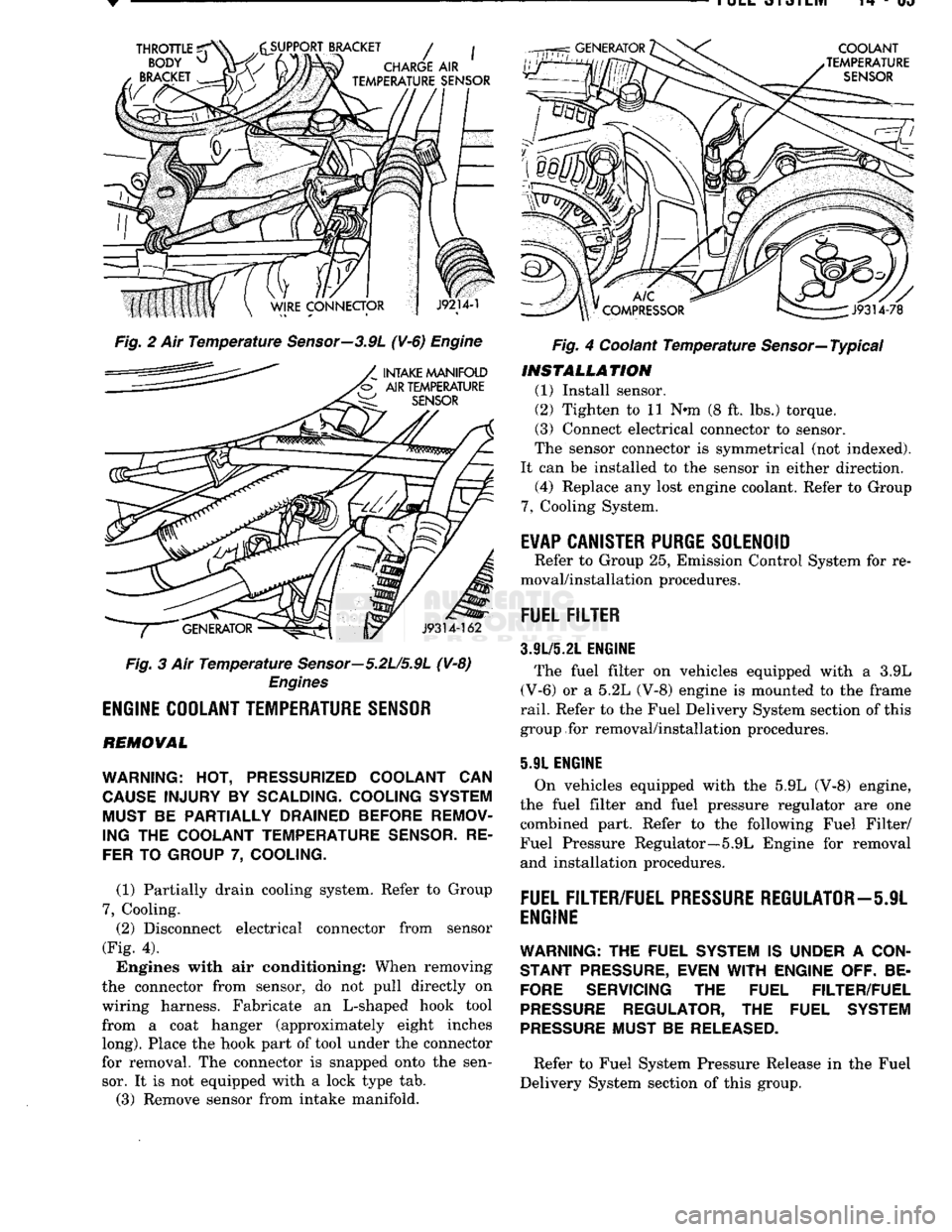
Fig. 2 Ait Temperature Sensor—3.9L (¥-6) Engine
Fig. 3 Air Temperature Sensor—5.2U5.9L (V-8)
Engines
ENGINE
COOLANT
TEMPERATURE
SENSOR
REMOVAL
WARNING:
HOT,
PRESSURIZED COOLANT
CAN
CAUSE
INJURY
BY
SCALDING- COOLING SYSTEM MUST
BE
PARTIALLY DRAINED BEFORE REMOV
ING
THE
COOLANT TEMPERATURE
SENSOR.
RE
FER
TO
GROUP
7,
COOLING.
(1) Partially drain cooling system. Refer to Group
7,
Cooling. (2) Disconnect electrical connector from sensor
(Fig. 4).
Engines with air conditioning: When removing
the connector from sensor, do not pull directly on
wiring harness. Fabricate an L-shaped hook tool from a coat hanger (approximately eight inches
long).
Place the hook part of tool under the connector
for removal. The connector is snapped onto the sen sor. It is not equipped with a lock type tab.
(3) Remove sensor from intake manifold. Fig. 4 Coolant Temperature Sensor—Typical
INSTALLATION
(1) Install sensor.
(2) Tighten to 11 Nnn (8 ft. lbs.) torque.
(3) Connect electrical connector to sensor.
The sensor connector is symmetrical (not indexed).
It can be installed to the sensor in either direction. (4) Replace any lost engine coolant. Refer to Group
7,
Cooling System.
E¥AP
CANISTER
PURGE
SOLENOID
Refer to Group 25, Emission Control System for re
moval/installation procedures.
FUEL
FILTER
3.9L/5.21.
ENGINE
The fuel filter on vehicles equipped with a 3.9L
(V-6) or a 5.2L (V-8) engine is mounted to the frame
rail.
Refer to the Fuel Delivery System section of this
group for removal/installation procedures.
5.91 ENGINE
On vehicles equipped with the 5.9L (V-8) engine,
the fuel filter and fuel pressure regulator are one combined part. Refer to the following Fuel Filter/
Fuel Pressure Regulator—5.9L Engine for removal and installation procedures.
FUEL
FILTER/FUEL
PRESSURE
REGULATOR—5JL
ENGINE
WARNING:
THE FUEL SYSTEM IS UNDER A
CON
STANT
PRESSURE,
EVEN
WITH
ENGINE OFF. BE
FORE
SERVICING THE FUEL FILTER/FUEL
PRESSURE
REGULATOR, THE FUEL SYSTEM
PRESSURE
MUST BE
RELEASED.
Refer to Fuel System Pressure Release in the Fuel
Delivery System section of this group.
Page 885 of 1502
14
- 66
FUEL
SYSTEM
REMOVAL
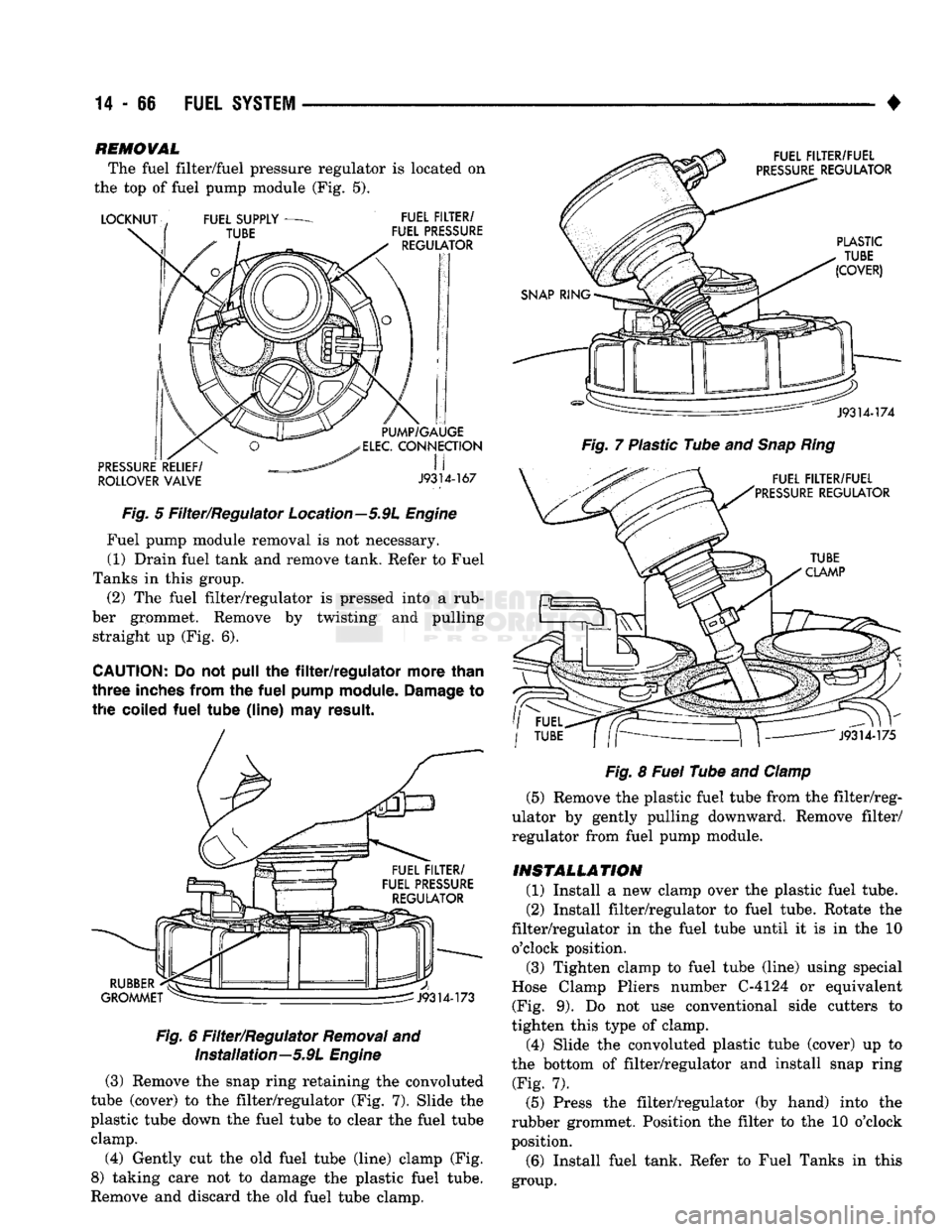
The fuel filter/fuel pressure regulator is located on
the top of fuel pump module (Fig. 5).
ROLLOVER
VALVE
J9314-167
Fig.
5 Filter/Regulator Location—5.9L
Engine
Fuel pump module removal is not necessary. (1) Drain fuel tank and remove tank. Refer to Fuel
Tanks in this group. (2) The fuel filter/regulator is pressed into a rub
ber grommet. Remove by twisting and pulling straight up (Fig. 6).
CAUTION;
Do not pull the
filter/regulator
more
than
three
inches
from
the
fuel
pump
module.
Damage
to
the
coiled
fuel
tube
(line)
may
result.
Fig.
6 Filter/Regulator
Removal
and Installation—5.9L
Engine
(3) Remove the snap ring retaining the convoluted
tube (cover) to the filter/regulator (Fig. 7). Slide the
plastic tube down the fuel tube to clear the fuel tube clamp.
(4) Gently cut the old fuel tube (line) clamp (Fig.
8) taking care not to damage the plastic fuel tube.
Remove and discard the old fuel tube clamp.
Fig.
7 Plastic Tube and
Snap
Ring
Fig.
8
Fuel
Tube and
Clamp
(5) Remove the plastic fuel tube from the filter/reg
ulator by gently pulling downward. Remove filter/
regulator from fuel pump module.
INSTALLATION
(1) Install a new clamp over the plastic fuel tube.
(2) Install filter/regulator to fuel tube. Rotate the
filter/regulator in the fuel tube until it is in the 10 o'clock position. (3) Tighten clamp to fuel tube (line) using special
Hose Clamp Pliers number C-4124 or equivalent (Fig. 9). Do not use conventional side cutters to
tighten this type of clamp.
(4) Slide the convoluted plastic tube (cover) up to
the bottom of filter/regulator and install snap ring (Fig. 7).
(5) Press the filter/regulator (by hand) into the
rubber grommet. Position the filter to the 10 o'clock
position.
(6) Install fuel tank. Refer to Fuel Tanks in this
group.