1993 DODGE TRUCK fuel type
[x] Cancel search: fuel typePage 38 of 1502

•
LUBRICATION
AND
MAINTENANCE
0 - 19 ETBE— This fuel is a mixture of unleaded gasoline
and up to 17 percent ETBE (Ethyl Tertiary Butyl
Ether).
Unleaded gasoline blended with ETBE is ac ceptable.
METHANOL—Do not use unleaded gasoline
blended with methanol. The use of this type of alco hol can result in engine performance and damage to
critical components. Engine problems that result
from the use of methanol possibly will not be covered by the new vehicle warranty.
Certain brands of unleaded gasoline contain a per
centage of unidentified alcohol. These types of un
leaded gasoline are not recommended.
ADDITIVES MIXED
WITH
GASOLINE
Use of fuel system cleaning additives should be
avoided. Many of these solutions could contain highly
active solvents. This type of solvent can be harmful
to the gasket and diaphragm material within the fuel system.
DIESEL
ENGINE FUEL REQUIREMENTS
All Diesel engines normally can use number 2D
Diesel fuel for most year-round operations. A fuel
conforming to ASTM Specification D-975 is recom
mended. For extreme cold-weather operation (below
-18°C/0°F), or for prolonged cold-climate operation ei
ther:
• Use No. ID fuel, or
• Add an equal quantity of kerosene to No. 2D fuel (a 50/50 mixture).
Both methods provide protection against fuel gel
ling and waxing.
Diesel fuel seldom is without water contamination.
To help prevent fuel system malfunctions, drain all accumulated water from the separators periodically.
VACUUM OPERATED,
EMISSION
CONTROL
COMPONENTS
MAINTENANCE SCHEDULE
The following emission controls should be replaced
at the interval specified in the maintenance sched
ule:
• Bi-level purge check valves
• Delay valves
• Heated air temperature sensor (HATS)
• Air cleaner vacuum motors
EXHAUST
GAS RECIRCULATION (EGR)
SYSTEM
MAINTENANCE SCHEDULE
Replace the EGR valve and tube, and clean the
passages at the interval specified in maintenance schedule. If necessary, refer to Group 25—Emission
Control Systems for additional information.
OXYGEN
(02)
SENSOR
MAINTENANCE SCHEDULE
Replace the 02 sensor at the interval specified in
maintenance schedule.
IGNITION
CABLES,
DISTRIBUTOR CAP AND
ROTOR
MAINTENANCE SCHEDULE
Replace the ignition cables, distributor cap, and ro
tor at the interval specified in maintenance schedule.
Inspect the distributor for excessive wear and re
place, as necessary. Refer to Group 8D—Ignition Sys
tems for additional information.
IGNITION TIMING
MAINTENANCE SCHEDULE
Test and adjust, if necessary, the ignition timing at
the interval specified in maintenance schedule. Refer
to the specifications listed on the engine Emission Control Information label. Refer to Group 8D—Igni
tion Systems and to Group 25—Emission Control Systems for additional service information.
SPARK
PLUGS MAINTENANCE SCHEDULE
Replace the spark plugs at the interval specified in
maintenance schedule. Refer to the Spark Plugs
chart below and to Group 8D—Ignition Systems for additional service information.
SPARK
PLUGS
ENGINE
SPARK
PLUG
SPARK
PLUG
GAP
TORQUE
3.9L
5.2L
5.9L
RN12YC
RN12YC
RN12YC
0.9 mm
(0.035
in.)
0.9 mm
(0.035
in.)
0.9 mm
(0.035
in.) 41 N*m (30 ft. lb.)
41 NVn (30 ft. lb.)
41 N*m (30 ft. lb.)
J9100-17
BATTERY
MAINTENANCE SCHEDULE
Replace battery at interval specified in mainte
nance schedule.
Page 338 of 1502
•
ELECTRICAL
8A - 17
DIAGNOSTIC
TROUBLE
CODES
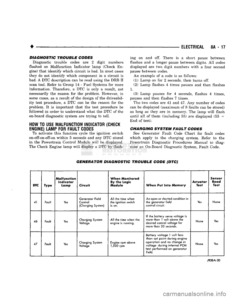
Diagnostic trouble codes are 2 digit numbers
flashed on Malfunction Indicator lamp (Check En
gine) that identify which circuit is bad. In most cases
they do not identify which component in a circuit is
bad. A DTC description can be read using the DRB II scan tool. Refer to Group 14 - Fuel Systems for more
information. Therefore, a DTC is only a result, not
necessarily the reason for the problem. However, in
some cases, as a result of the design of the driveabil- ity test procedure, a DTC can be the reason for the
problem. It is important that the test procedure be followed in order to understand what the DTC of the
on-board diagnostic system are trying to tell.
HOW
TO
USE
MALFUNCTION
INDICATOR
(CHECK
ENGINE)
LAMP
FOR
FAULT
CODES
To activate this function cycle the ignition switch
on-off-on-off-on within 5 seconds and any DTC stored
in the Powertrain Control Module will be displayed.
The Check Engine lamp will display a DTC by flash ing on and off. There is a short pause between
flashes and a longer pause between digits. All codes
displayed are two digit numbers with a four second
pause between codes. An example of a code is as follows:
(1) Lamp on for 2 seconds, then turns off.
(2) Lamp flashes 4 times pauses and then flashes
1.
(3) Lamp pauses for 4 seconds, flashes 4 times,
pauses and then flashes 7 times.
The two codes are 41 and 47. Any number of codes
can be displayed (maximum of 8 faults can be stored) as long as they are in memory. The lamp will flash
until all of them (including 55) are displayed (55 =
End of test).
CHARGING
SYSTEM
FAULT
CODES
See Generator Fault Code Chart for fault codes
which apply to the charging system. Refer to the
Powertrain Diagnostic Procedures Manual to diag
nose an On-Board Diagnostic System, Fault Code.
GENERATOR
DIAGNOSTIC
TROUBLE
CODE
(DTC)
DTC
Type
Malfunction
Indicator
Lamp
Circuit
When
Monitored
By
the
Logic
Module
When
Put Into
Memory
Actuator
Test
Sensor
Read
Test
41 Fault
Yes
Generator Field
Control
(Charging
System)
All the
time
when
the ignition switch
is
on.
An
open or shorted condition in
the generator
field
control circuit.
Yes
None
46 Fault
Yes
Charging
System
Voltage
All the
time
when the
engine
is
running.
If the
battery
sense
voltage is
more than 1 volt
above
the
desired
control voltage for
more than 20
seconds.
None
Yes
47 Fault
Yes
Charging
System
Voltage
Engine
rpm
above
1,500 rpm Battery voltage
1
volt
less
than set point during engine
operation and no
change
in
voltage
during
internal
PCM
test performed on generator field.
None
Yes
J938A-20
Page 368 of 1502
•
IGNITION SYSTEMS
80-17
or punctured, there will
be a
noticeable spark jump
from
the
damaged area
to the
test probe.
The
cable
running from
the
ignition coil
to the
distributor
cap
can
be
checked
in the
same manner. Cracked, dam aged
or
faulty cables should
be
replaced with resis
tance type cable. This
can be
identified
by the
words ELECTRONIC SUPPRESSION printed
on the
cable
jacket.
Use
an
ohmmeter
to
test
for
open circuits, exces
sive resistance
or
loose terminals. Remove
the
dis
tributor
cap
from
the
distributor.
Do not
remove cables from
cap.
Remove cable from spark plug.
Connect ohmmeter
to
spark plug terminal
end of ca
ble
and to
corresponding electrode
in
distributor
cap.
Resistance should
be 250 to 1000
Ohms
per
inch
of
cable.
If not,
remove cable from distributor
cap
tower and connect ohmmeter
to the
terminal ends
of
cable.
If resistance
is not
within specifications
as
found
in
the Spark Plug Cable Resistance chart, replace
the
cable. Test
all
spark plug cables
in
this manner.
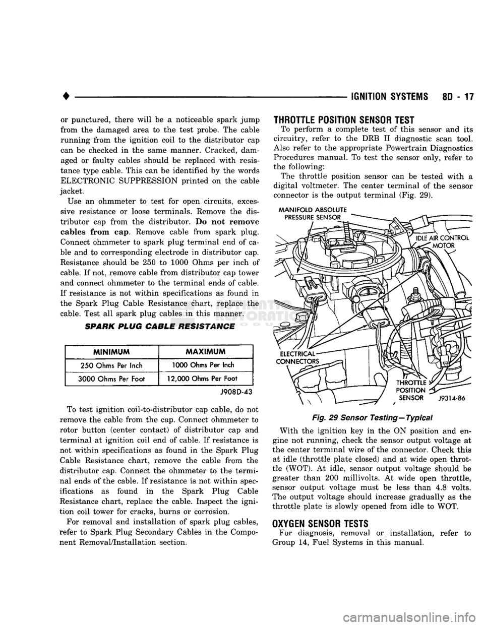
SPARK
PLUG CABLE RESISTANCE
MINIMUM
MAXIMUM
250
Ohms
Per
Inch
1000
Ohms
Per
Inch
3000
Ohms
Per
Foot
12,000
Ohms
Per
Foot
J908D-43 To test ignition coil-to-distributor
cap
cable,
do not
remove
the
cable from
the cap.
Connect ohmmeter
to
rotor button (center contact)
of
distributor
cap and
terminal
at
ignition coil
end of
cable.
If
resistance
is
not within specifications
as
found
in the
Spark Plug
Cable Resistance chart, remove
the
cable from
the
distributor
cap.
Connect
the
ohmmeter
to the
termi
nal ends
of the
cable.
If
resistance
is not
within spec
ifications
as
found
in the
Spark Plug Cable
Resistance chart, replace
the
cable. Inspect
the
igni
tion coil tower
for
cracks, burns
or
corrosion.
For removal
and
installation
of
spark plug cables,
refer
to
Spark Plug Secondary Cables
in the
Compo nent Removal/Installation section.
THROTTLE POSITION
SENSOR
TEST
To perform
a
complete test
of
this sensor
and its
circuitry, refer
to the DRB II
diagnostic scan tool.
Also refer
to the
appropriate Powertrain Diagnostics
Procedures manual.
To
test
the
sensor only, refer
to
the following: The throttle position sensor
can be
tested with
a
digital voltmeter.
The
center terminal
of the
sensor
connector
is the
output terminal
(Fig. 29).
MANIFOLD ABSOLUTE
Fig.
29
Sensor
Testing—Typical With
the
ignition
key in the ON
position
and en
gine
not
running, check
the
sensor output voltage
at
the center terminal wire
of the
connector. Check this at idle (throttle plate closed)
and at
wide open throt
tle (WOT).
At
idle, sensor output voltage should
be
greater than
200
millivolts.
At
wide open throttle, sensor output voltage must
be
less than
4,8
volts.
The output voltage should increase gradually
as the
throttle plate
is
slowly opened from idle
to WOT.
OXYGEN
SENSOR
TESTS
For diagnosis, removal
or
installation, refer
to
Group
14,
Fuel Systems
in
this manual.
Page 607 of 1502

9
- 2
ENGINES
rial surrounds each mounting hole. Excess material
can easily be wiped off. Components should be
torqued in place within 15 minutes. The use of a lo cating dowel is recommended during assembly to pre
vent smearing the material off location.
ENGINE PERFORMANCE
To provide best vehicle performance and lowest ve
hicle emissions, it is most important that the tune-up
be done accurately. Use the specifications listed on
the Vehicle Emission Control Information label found on the engine compartment hood.
(1) Test cranking amperage draw (refer to Group
8B,
Battery/Starter/Generator Service for the proper
procedures).
(2) Tighten the intake manifold bolts (refer to
Group 11, Exhaust System and Intake Manifold for
the proper specifications). (3) Perform cylinder compression test:
(a) Check engine oil level and add oil, if neces
sary.
(b) Drive the vehicle until engine reaches normal
operating temperature. (c) Select a route free from traffic and other
forms of congestion, observe all traffic laws and
briskly accelerate through the gears several times. The higher engine speed may help clean out valve seat deposits which can prevent accurate compres
sion readings.
CAUTION:
DO NOT
overspeed
the
engine.
(d) Remove all spark plugs from engine. As
spark plugs are being removed, check electrodes for
abnormal firing indicators - fouled, hot, oily, etc.
Record cylinder number of spark plug for future
reference.
(e) Disconnect coil wire from distributor and se
cure to good ground to prevent a spark from start
ing a fire.
(f) Be sure throttle blades are fully open during
the compression check. (g) Insert compression gage adaptor into the
No.l spark plug hole. Crank engine until maxi
mum pressure is reached on gauge. Record this
pressure as No.l cylinder pressure.
(h) Repeat Step 3g for all remaining cylinders.
(i) Compression should not be less than 689 kPa
(100 psi) and not vary more than 172 kPa (25 psi)
from cylinder to cylinder.
(j) If cylinder(s) have abnormally low compres
sion pressures, repeat steps 3a through 3h. (k) If the same cylinder(s) repeat an abnormally
low reading, it could indicate the existence of a
problem in the cylinder.
The recommended compression pressures are
to be used only as a guide to diagnosing engine
problems. An engine should NOT be disassem bled to determine the cause of low compression
unless some malfunction is present. (4) Clean or replace spark plugs as necessary. Ad
just gap (refer to Group 8D, Ignition System for gap adjustment and torque).
(5) Test resistance of spark plug cables (refer to
Group 8D, Ignition System.
(6) Inspect the primary wire. Test coil output volt
age,
primary and secondary resistance. Replace parts as necessary (refer to Group 8D, Ignition System and
make necessary adjustment).
(7) Set ignition timing to specifications (refer to
Specification Label on engine compartment hood).
(8) Perform a combustion analysis.
(9) Test fuel pump for pressure and vacuum (refer
to Group 14, Fuel System for the proper specifica
tions).
(10) Inspect air filter element (refer to Group 0,
Lubrication and Maintenance for the proper proce
dure).
(11) Inspect crankcase ventilation system (refer to
Group 0, Lubrication and Maintenance for the proper
procedure).
(12) For emission controls refer to Group 25, Emis
sion Controls System for service procedures.
(13) Inspect and adjust accessory belt drives (refer
to Group 7, Cooling System for the proper adjust
ments).
(14) Road test vehicle as a final test.
H0NIN6
CYLINDER
BORES
Before honing, stuff plenty of clean shop towels un
der the bores and over the crankshaft to keep abra sive materials from entering the crankshaft area.
(1) Used carefully, the Cylinder Bore Sizing Hone
C-823 equipped with 220 grit stones, is the best tool
for this job. In addition to deglazing, it will reduce
taper and out-of-round as well as removing light scuffing, scoring or scratches. Usually a few strokes
will clean up a bore and maintain the required lim
its.
CAUTION:
DO NOT use rigid type
hones
to remove
cylinder
wall
glaze.
(2) Deglazing of the cylinder walls may be done if
the cylinder bore is straight and round. Use a cylin
der surfacing hone, Honing Tool C-3501, equipped
with 280 grit stones (C-3501-3810). 20-60 strokes, de
pending on the bore condition, will be sufficient to
provide a satisfactory surface. Using honing oil C-3501-3880 or a light honing oil available from ma
jor oil distributors.
CAUTION:
DO NOT use engine or
transmission
oil, mineral
spirits
or
kerosene.
Page 617 of 1502
9
- 12
ENGINES
•
CONDITION
POSSIBLE
CAUSES
CORRECTION
EXCESSIVE
EXHAUST
SMOKE
(Cont'd)
More
than
one
sealing washer
under an injector.
Check
and remove
extra
washer.
Improperly operating injectors.
Check
and replace inoperative injectors.
Improperly operating or over-
fueled injection pump.
Replace
injection pump.
Piston
rings
not sealing
(blue smoke). Perform blow-by check. Correct as required.
ENGINE
WILL
NOT
SHUT-OFF
Fuel shutoff valve inoperative.
Engine
running on fumes drawn into the air intake.
Stop
the engine mechanically
with
lever on the
fuel
pump.
Check/replace
sealing washer, piston and
spring.
Check
the air intake ducts for the source of the fumes.
WARNING:
In
ease
of engine runaway due to flammable
fumes
from gasoline spills or turbocharger oil leaks
being
sucked
into the
engine,
shut off engine ignition switch first then use a CO* or dry
chemical type
fire
extinguisher
and direct the
spray
under
the
front
bumper to
remove
oxygen
supply. The engine air
intake
is on the
passenger
side
behind the bumper. The
fire
extinguisher
must
bo
directed at this location for emergency shutdown conditions.
COOLANT
TEMPERA
TURE
ABOVE
NORMAL
Low
coolant level.
(a) Check coolant level. Add coolant, if necessary.
(b) Locate and correct the source of the coolant leak. Refer to
troubleshooting
logic for coolant
loss.
Incorrect/improperly operating
pressure
cap.
Replace
cap
with
the correct rating for the
system.
High
lube oil level.
Check/drain
oil to correct level.
Loose
drive belt on water
pump/fan.
Check/replace
belt or belt tensioner.
Inadequate air flow to the radiator. Check/repair radiator core, fan shroud and fan clutch as
required.
Radiator
fins
plugged.
Blow
debris from fins.
Collapsed
radiator
hose.
Replace
the
hose.
Improperly operating tempera
ture
sensor/gauge.
Verify
that
the
gauge
and temperature
sensor
are accurate.
Replace
gauge/sensor,
if bad.
Improperly operating, incorrect
or
no thermostat.
Check
and replace the thermostat.
Air
in the cooling
system.
(a) Make sure the
fill
rate
is not being exceeded and the correct
vented thermostat is installed.
(b) Check for loose hose
clamps.
Tighten if
loose.
(c) If aeration continued, check for a
compression
leak through the head gasket.
Inoperative water pump.
Check
and replace the water pump.
incorrect injection pump timing. Verify pump timing marks are aligned. Check/time the injector
pump
(refer
to Group 7,
Cooling
System).
J9209-56
SERVICE DIAGNOSIS (DIESEL ENGINE) - PERFORMANCE (CONT.)
Page 622 of 1502
•
3.9L ENGINE
9 - 17
3.9L
ENGINE SERVICE PROCEDURES
INDEX
page
Camshaft
31
Crankshaft
38
Crankshaft Main Bearings
39
Crankshaft Rear
Oil
Seals
. 40
Cylinder Block
41
Cylinder Head Cover
. , 21
Cylinder Heads
. 22
Distributor
33
Engine
Assembly .........................
20
Engine
Front Mounts
17
Engine
Rear Mount
18
Front Crankshaft
Oil
Seal Replacement ........
31
GENERAL INFORMATION
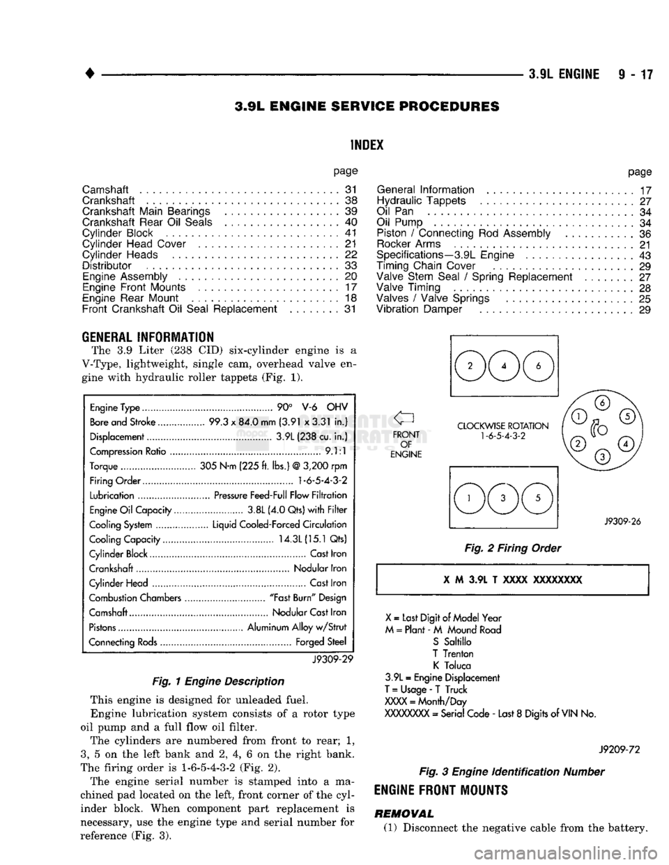
The 3.9 Liter (238 CID) six-cylinder engine is a
V-Type, lightweight, single cam, overhead valve en gine with hydraulic roller tappets (Fig. 1).
Engine
Type
90° V-6 OHV
Bore
and Stroke 99.3
x
84.0 mm (3.91 x3.31
in.)
Displacement 3.9L (238 cu.
in.)
Compression
Ratio
9.1:1
Torque 305 N-m (225
ft.
lbs.)
@
3,200
rpm
Firing Order.... 1-6-5-4-3-2
Lubrication
Pressure
Feed-Full Flow
Filtration
Engine
Oil
Capacity 3.8L (4.0 Qts)
with Filter
Cooling
System
Liquid Cooled-Forced
Circulation
Cooling Capacity 14.3L
(15.1
Qts)
Cylinder Block Cast Iron
Crankshaft Nodular Iron
Cylinder Head
Cast
Iron
Combustion Chambers "Fast
Burn"
Design
Camshaft Nodular
Cast
Iron
Pistons
Aluminum Alloy
w/Strut
Connecting
Rods
Forged Steel
J9309-29
Fig.
1
Engine
Description
This engine is designed for unleaded fuel. Engine lubrication system consists of a rotor type
oil pump and a full flow oil filter.
The cylinders are numbered from front to rear; 1,
3,
5 on the left bank and 2, 4, 6 on the right bank.
The firing order is
1-6-5-4-3-2
(Fig. 2).
The engine serial number is stamped into a ma
chined pad located on the left, front corner of the cyl
inder block. When component part replacement is
necessary, use the engine type and serial number for
reference (Fig. 3).
page
General
Information
17
Hydraulic Tappets
27
Oil
Pan 34
Oil Pump
34
Piston
/
Connecting
Rod
Assembly
36
Rocker
Arms
21
Specifications—3.9L Engine
43
Timing Chain Cover
29
Valve Stem Seal
/
Spring Replacement ........
27
Valve Timing
28
Valves
/
Valve Springs
25
Vibration
Damper
29
J9309-26
Fig.
2 Firing Order i M 3.9L T xxxx
XXXXXXXX
X
=
Last Digit
of
Model Year
M
=
Plant -
M
Mound
Road
S
Sabillo
T Trenton
K
Toluca
3.9L
=
Engine Displacement
T
=
Usage
-
T Truck
XXXX
=
Month/Day
XXXXXXXX
- Serial Code -
Last
8
Digits of
VIN
No.
J9209-72
Fig.
3
Engine
identification
Number
ENGINE FRONT MOUNTS
REMOVAL (1) Disconnect the negative cable from the battery.
Page 652 of 1502
5.2L
ENGINE
9 - 47
S.2L ENGINE
SERVICE
PROCEDURES
INDEX
page
Camshaft
. , . 61
Crankshaft
68
Crankshaft Main Bearings
69
Crankshaft Rear
Oil
Seals
...... ........
70
Cylinder Block ...........................
71
Cylinder Head Cover
. . . . 51
Cylinder Heads
52
Distributor
62
Engine
Assembly
. 50
Engine
Front Mounts
47
Engine
Rear Mount ...............
48
Front Crankshaft
Oil
Seal Replacement
. . 61
GENERAL
INFORMATION
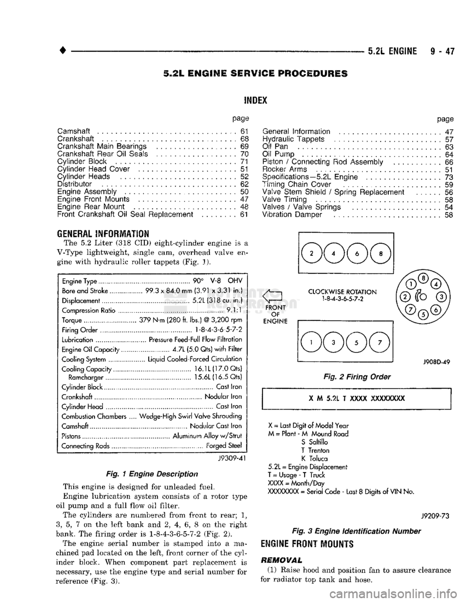
The 5.2 Liter (318 CID) eight-cylinder engine is a
V-Type lightweight, single cam, overhead valve en gine with hydraulic roller tappets (Fig. J).
Engine
Type ....
90° V-8 OHV
Bore
and Stroke .....
99.3
x
84.0 mm
(3.91
x
3.31
in.)
Displacement................
5.2L(318cu.
in.)
Compression
Ratio ....... .
9.1:1
Torque .. 379 N-m (280
ft.
lbs.)
@
3,200
rpm
Firing Order .... 1-8-4-3-6-5-7-2
Lubrication
.......
Pressure
Feed-Full Flow
Filtration
Engine
Oil
Capacity......
4.7L
(5.0 Qts)
with Filter
Cooling System ...... Liquid Cooled-Forced
Circulation
Cooling Capacity..........
16.1L(17.0Qts)
Ramcharger
15.6L
(16.5 Qts)
Cylinder Block
,
Cast
Iron
Crankshaft Nodular Iron
Cylinder Head ..............
Cast
Iron
Combustion Chambers
..
Wedge-High
Swirl Valve Shrouding
Camshaft Nodular Cast Iron
Pistons
Aluminum Alloy
w/Strut
Connecting
Rods...........
Forged
Steel
J9309-41
Fig. 1
Engine
Description
This engine is designed for unleaded fuel.
Engine lubrication system consists of a rotor type
oil pump and a full flow oil filter.
The cylinders are numbered from front to rear; 1?
3,
5, 7 on the left bank and 2, 4, 6, 8 on the right
bank. The firing order is 1-8-4-3-6-5-7-2 (Fig. 2).
The engine serial number is stamped into a ma
chined pad located on the left, front corner of the cyl
inder block. When component part replacement is
necessary, use the engine type and serial number for
reference (Fig. 3).
page
General
Information
.......................
47
Hydraulic Tappets
57
Oil
Pan . 63
Oil Pump
. 64
Piston
/
Connecting
Rod
Assembly
66
Rocker
Arms
51
Specifications—5.2L Engine
73
Timing Chain Cover ................
59
Valve Stem Shield
/
Spring Replacement
56
Valve Timing
. 58
Valves
/
Valve Springs
54
Vibration
Damper
. . 58
J908D-49
Fig.
2 Firing Order
X
M 5.2L T
XXXX
XXXXXXXX
X
~
Last Digit of
Model
Year
M
=
Plant
- M
Mound
Road
S
Saltillo
T
Trenton
K
Toluca
5.2L
=
Engine Displacement
T
=
Usage
-
T Truck
XXXX
=
Month/Day
XXXXXXXX
=
Serial Code
-
Last
8
Digits
of
VIN
No.
J9209-73
Fig.
3
Engine
Identification
Number
ENGINE
FRONT
MOUNTS
REMOVAL
(1) Raise hood and position fan to assure clearance
for radiator top tank and hose.
Page 682 of 1502
5.9L
ENGINE SERVICE PROCEDURES
INDEX
page
Camshaft
91
Crankshaft
98
Crankshaft Main Bearings
99
Crankshaft Rear
Oil
Seals
100
Cylinder
Block
101
Cylinder
Head Cover
81
Cylinder
Heads
82
Distributor
92
Engine Assembly
80
Engine
Front
Mounts
77
Engine Rear Mount
78
Front
Crankshaft
Oil
Seal Replacement
91
page
General
Information
77
Hydraulic
Tappets
87
Oil
Pan 93
Oil Pump
. 94
Piston
/
Connecting
Rod
Assembly
96
Rocker Arms
81
Specifications—5.9L
Engine
103
Timing
Chain Cover
89
Valve Stem Shield
/
Spring Replacement
86
Valve
Timing
. 88
Valves
/
Valve Springs
84
Vibration
Damper
88
GENERAL
INFORMATION
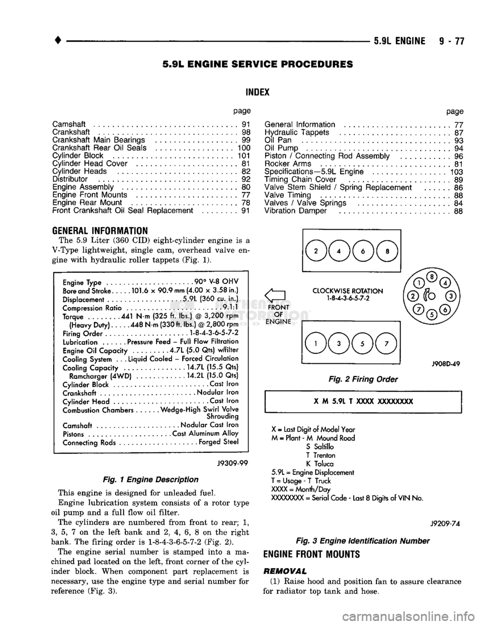
The 5.9 Liter (360 CID) eight-cylinder engine is a
V-Type lightweight, single cam, overhead valve en
gine with hydraulic roller tappets (Fig. 1).
Engine Type .90° V-8 OHV
Bore and Stroke 101.6 x 90.9
mm
(4.00 x 3.58 in.)
Displacement 5.9L (360 cu. in.)
Compression Ratio 9.1:1
Torque 441 N-m (325 ft. lbs.) @ 3,200 rpm (Heavy Duty). 448 N-m (330 ft. lbs.)
@
2,800 rpm
Firing Order
1-8-4-3-6-5-7-2
Lubrication ...... Pressure Feed - Full Flow Filtration
Engine Oil Capacity .4.7L (5.0 Qts) w/filter
Cooling System . .
.
Liquid Cooled - Forced Circulation Cooling Capacity ..... . . 14.7L (15.5 Qts)
Ramcharger (4WD) 14.2L (15.0 Qts)
Cylinder Block Cast Iron Crankshaft
-
Nodular Iron
Cylinder Head • . Cast Iron Combustion Chambers Wedge-High Swirl Valve
Shrouding
Camshaft Nodular Cast Iron Pistons Cast Aluminum Alloy
Connecting Rods Forged Steel
J9309-99
Fig. 1
Engine
Description
This engine is designed for unleaded fuel.
Engine lubrication system consists of a rotor type
oil pump and a full flow oil filter.
The cylinders are numbered from front to rear; 1,
3,
5, 7 on the left bank and 2, 4, 6, 8 on the right
bank. The firing order is
1-8-4-3-6-5-7-2
(Fig. 2).
The engine serial number is stamped into a ma
chined pad located on the left, front corner of the cyl
inder block. When component part replacement is
necessary, use the engine type and serial number for
reference (Fig. 3).
o
FRONT OF
ENGINE CLOCKWISE ROTATION
1-8-4-3-6-5-7-2
J908D-49
Fig. 2 Firing Order
X
M 5.9L T
XXXX
XXXXXXXX
X
= Last Digit of Model Year
M = Plant - M Mound Road S Saltillo
T Trenton K Toluca
5.9L = Engine Displacement
T
= Usage -
T
Truck
XXXX
= Month/Day
XXXXXXXX
= Serial Code - Last 8 Digits of
VIN
No.
J9209-74
Fig.
3
Engine
identification
Number
ENGINE
FRONT MOUNTS
REMOVAL (1) Raise hood and position fan to assure clearance
for radiator top tank and hose.