1993 DODGE TRUCK differential
[x] Cancel search: differentialPage 104 of 1502
FRONT
SUSPENSION
AND
AXLE
2 - 51
LUBRICANT
Multi-purpose API GL 5 quality hypoid gear lubri
cant should be used for Model 60 axles. MOPAR Hy
poid Gear Lubricant conforms to these specifications and is recommended.
CAUTION:
If a front axle is
submerged
in
water,
the
axle lubricant
must
be replaced immediately.
DRAIN AND REFILL
(1) Drive the vehicle until the gear lubricant
reaches normal operating temperature. (2) Raise and support the vehicle.
(3) Remove the lubricant fill hole plug from the
differential housing cover. (4) Remove the differential housing cover. Allow
the original lubricant to completely drain from the
housing and axle shaft tubes. (5) With standard differential, clean the differen
tial and the housing cavity with a flushing oil (or light engine oil). This will remove the residual lubricant and foreign matter. Do not use water, steam,
kerosene or gasoline for flushing. (6) Scrape the residual gasket from the housing
and cover mating surfaces. Clean the mating sur
faces with mineral spirits. Install a new cover gas
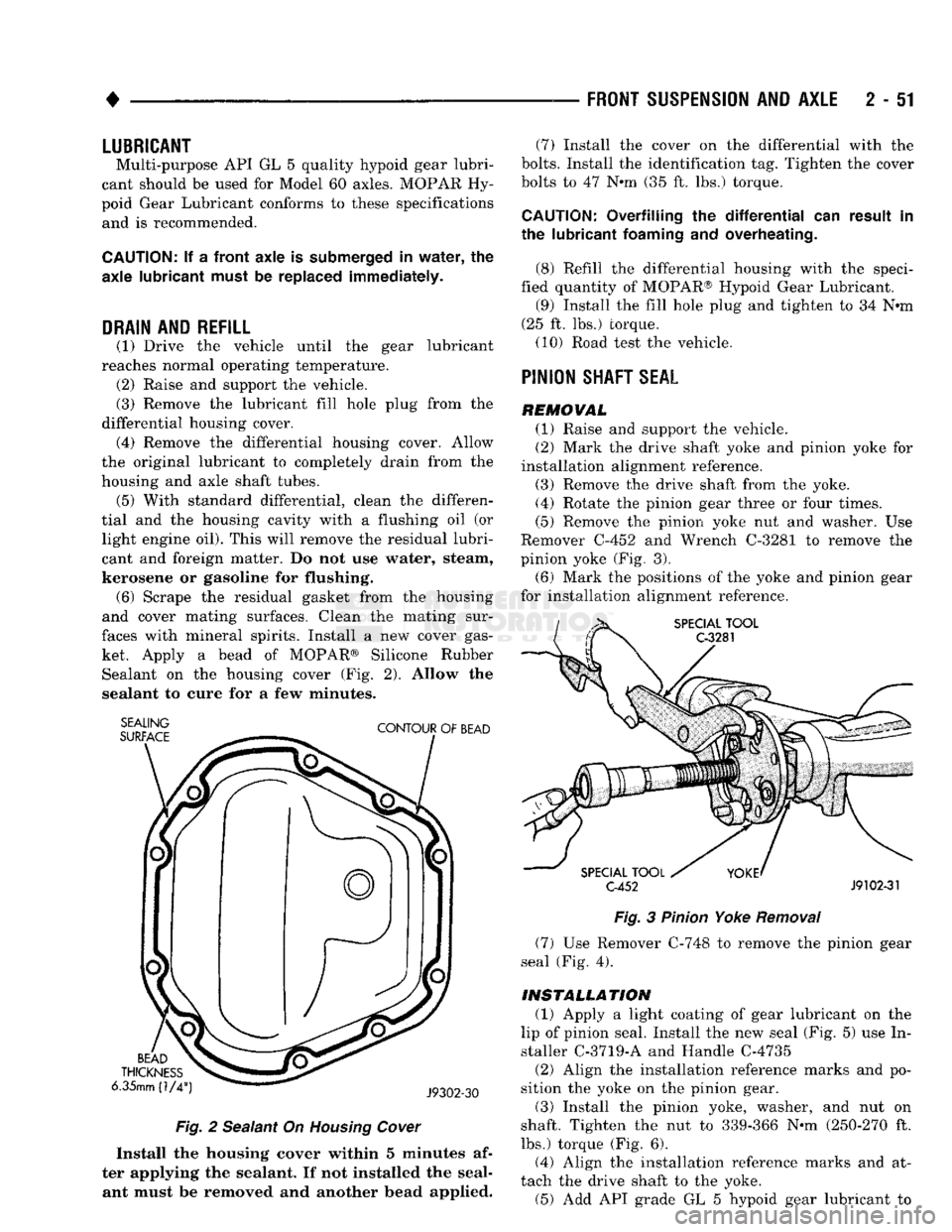
ket. Apply a bead of MOPAR® Silicone Rubber Sealant on the housing cover (Fig. 2). Allow the
sealant to cure for a few minutes.
SEALING
SURFACE
CONTOUR
OF
BEAD
BEAD
THICKNESS
6.35mm (1/4
J9302-30
Fig.
2 Sealant On
Housing
Cover
Install the housing cover within 5 minutes af
ter applying the sealant. If not installed the seal ant must be removed and another bead applied. (7) Install the cover on the differential with the
bolts.
Install the identification tag. Tighten the cover
bolts to 47 Nnn (35 ft. lbs.) torque.
CAUTION:
Overfilling the
differential
can result in
the lubricant
foaming
and overheating.
(8) Refill the differential housing with the speci
fied quantity of MOPAR® Hypoid Gear Lubricant. (9) Install the fill hole plug and tighten to 34 N«m
(25 ft. lbs.) torque. (10) Road test the vehicle.
PINION
SHAFT
SEAL
REMOVAL (1) Raise and support the vehicle.
(2) Mark the drive shaft yoke and pinion yoke for
installation alignment reference.
(3) Remove the drive shaft from the yoke.
(4) Rotate the pinion gear three or four times.
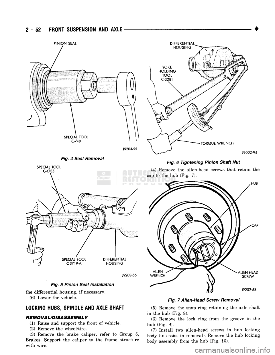
(5) Remove the pinion yoke nut and washer. Use
Remover C-452 and Wrench C-3281 to remove the
pinion yoke (Fig. 3).
(6) Mark the positions of the yoke and pinion gear
for installation alignment reference.
SPECIAL
TOOL
C-3281
SPECIAL
TOOL
C-452
J9102-31
Fig.
3
Pinion
Yoke
Removal
(7) Use Remover C-748 to remove the pinion gear
seal (Fig. 4).
INSTALLATION
(1) Apply a light coating of gear lubricant on the
lip of pinion seal. Install the new seal (Fig. 5) use In
staller C-3719-A and Handle C-4735
(2) Align the installation reference marks and po
sition the yoke on the pinion gear.
(3) Install the pinion yoke, washer, and nut on
shaft. Tighten the nut to 339-366 N-m (250-270 ft.
lbs.) torque (Fig. 6).
(4) Align the installation reference marks and at
tach the drive shaft to the yoke. (5) Add API grade GL 5 hypoid gear lubricant to
Page 105 of 1502
2
- 52
FRONT
SUSPENSION
AND
AXLE
•
PINION
SEAL
J9203-55
Fig. 4 Seal Removal
SPECIAL TOOL
G4735
J9203-56
Fig. 5 Pinion Seal Installation the differential housing, if necessary.
(6)
Lower the vehicle.
LOCKING HUBS, SPINDLE AND AXLE SHAFT
REM0VAL/D1SASSEMBL
Y
(1) Raise and support the front of vehicle. (2) Remove the wheel/tire.
(3) Remove the brake caliper, refer to Group 5,
Brakes. Support the caliper to the frame structure
with wire. DIFFERENTIAL
Fig. 6 Tightening Pinion Shaft Nut
(4) Remove the allen-head screws that retain the
cap to the hub (Fig. 7).
Fig. 7 Allen-Head Screw Removal (5) Remove the snap ring retaining the axle shaft
in the hub (Fig. 8).
(6)
Remove the lock ring from the groove in the
hub (Fig. 9).
(7) Install two allen-head screws in hub locking
body (to assist in removal). Remove the hub locking
body assembly from the hub (Fig. 10).
Page 107 of 1502
2
- 54
FRONT SUSPENSION
AND
AXLE
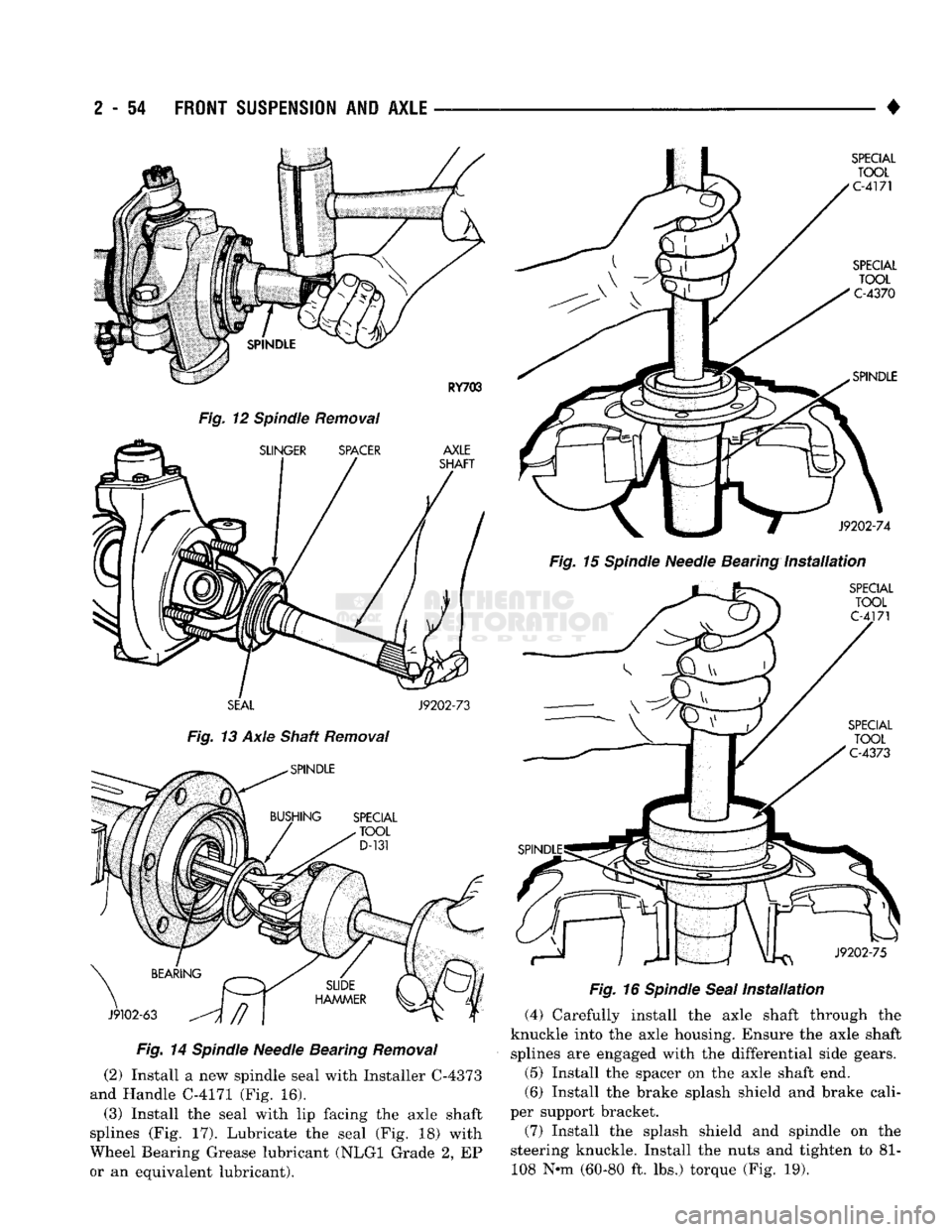
Fig.
12 Spindle Removal
SEAL
J9202-73
Fig.
13 Axle Shaft Removal
Fig.
14
Spindle
Needle Bearing
Removal
(2) Install a new spindle seal with Installer C-4373
and Handle C-4171 (Fig. 16).
(3) Install the seal with lip facing the axle shaft
splines (Fig. 17). Lubricate the seal (Fig. 18) with
Wheel Bearing Grease lubricant (NLGI Grade 2, EP
or an equivalent lubricant). •
Fig.
15
Spindle
Needle Bearing
Installation
Fig.
16
Spindle
Seal
Installation
(4) Carefully install the axle shaft through the
knuckle into the axle housing. Ensure the axle shaft splines are engaged with the differential side gears.
(5) Install the spacer on the axle shaft end.
(6) Install the brake splash shield and brake cali
per support bracket.
(7) Install the splash shield and spindle on the
steering knuckle. Install the nuts and tighten to 81- 108 N-m (60-80 ft. lbs.) torque (Fig. 19).
Page 112 of 1502
•
TAPERED
BUSHING
J9202-53
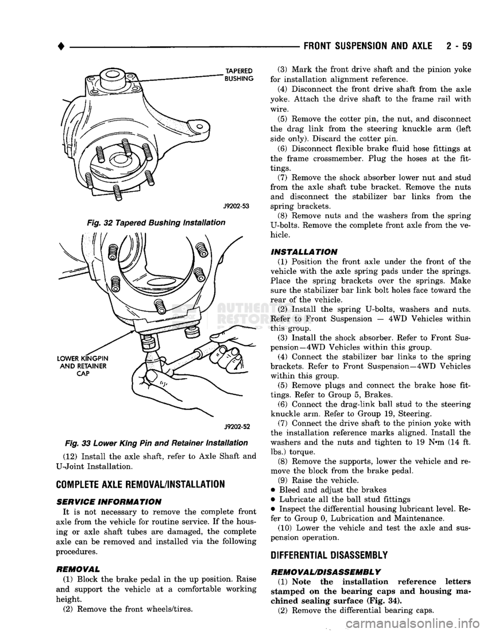
Fig.
32 Tapered
Bushing
Installation
J9202-52
Fig.
33
Lower
King
Pin and Retainer
Installation
(12) Install the axle shaft, refer to Axle Shaft and
U-Joint Installation.
COMPLETE
AXLE REMOVAL/INSTALLATION SERVICE
INFORMATION
It is not necessary to remove the complete front
axle from the vehicle for routine service. If the hous
ing or axle shaft tubes are damaged, the complete axle can be removed and installed via the following
procedures.
REMOVAL
(1) Block the brake pedal in the up position. Raise
and support the vehicle at a comfortable working
height.
(2) Remove the front wheels/tires.
FRONT SUSPENSION
AND
AXLE
2 - 59
(3) Mark the front drive shaft and the pinion yoke
for installation alignment reference.
(4) Disconnect the front drive shaft from the axle
yoke. Attach the drive shaft to the frame rail with
wire.
(5) Remove the cotter pin, the nut, and disconnect
the drag link from the steering knuckle arm (left side only). Discard the cotter pin.
(6) Disconnect flexible brake fluid hose fittings at
the frame crossmember. Plug the hoses at the fit
tings.
(7) Remove the shock absorber lower nut and stud
from the axle shaft tube bracket. Remove the nuts and disconnect the stabilizer bar links from the
spring brackets. (8) Remove nuts and the washers from the spring
U-bolts. Remove the complete front axle from the ve
hicle.
INSTALLATION (1) Position the front axle under the front of the
vehicle with the axle spring pads under the springs.
Place the spring brackets over the springs. Make sure the stabilizer bar link bolt holes face toward the
rear of the vehicle.
(2) Install the spring U-bolts, washers and nuts.
Refer to Front Suspension — 4WD Vehicles within
this group. (3) Install the shock absorber. Refer to Front Sus
pension—4 WD Vehicles within this group.
(4) Connect the stabilizer bar links to the spring
brackets. Refer to Front Suspension—4WD Vehicles within this group.
(5) Remove plugs and connect the brake hose fit
tings.
Refer to Group 5, Brakes. (6) Connect the drag-link ball stud to the steering
knuckle arm. Refer to Group 19, Steering. (7) Connect the drive shaft to the pinion yoke with
the installation reference marks aligned. Install the
washers and the nuts and tighten to 19 N-m (14 ft. lbs.) torque.
(8) Remove the supports, lower the vehicle and re
move the block from the brake pedal.
(9) Raise the vehicle.
• Bleed and adjust the brakes
• Lubricate all the ball stud fittings
• Inspect the differential housing lubricant level. Re
fer to Group 0, Lubrication and Maintenance.
(10) Lower the vehicle and test the axle and sus
pension operation.
DIFFERENTIAL DISASSEMBLY
REMOVAL/DISASSEMBLY
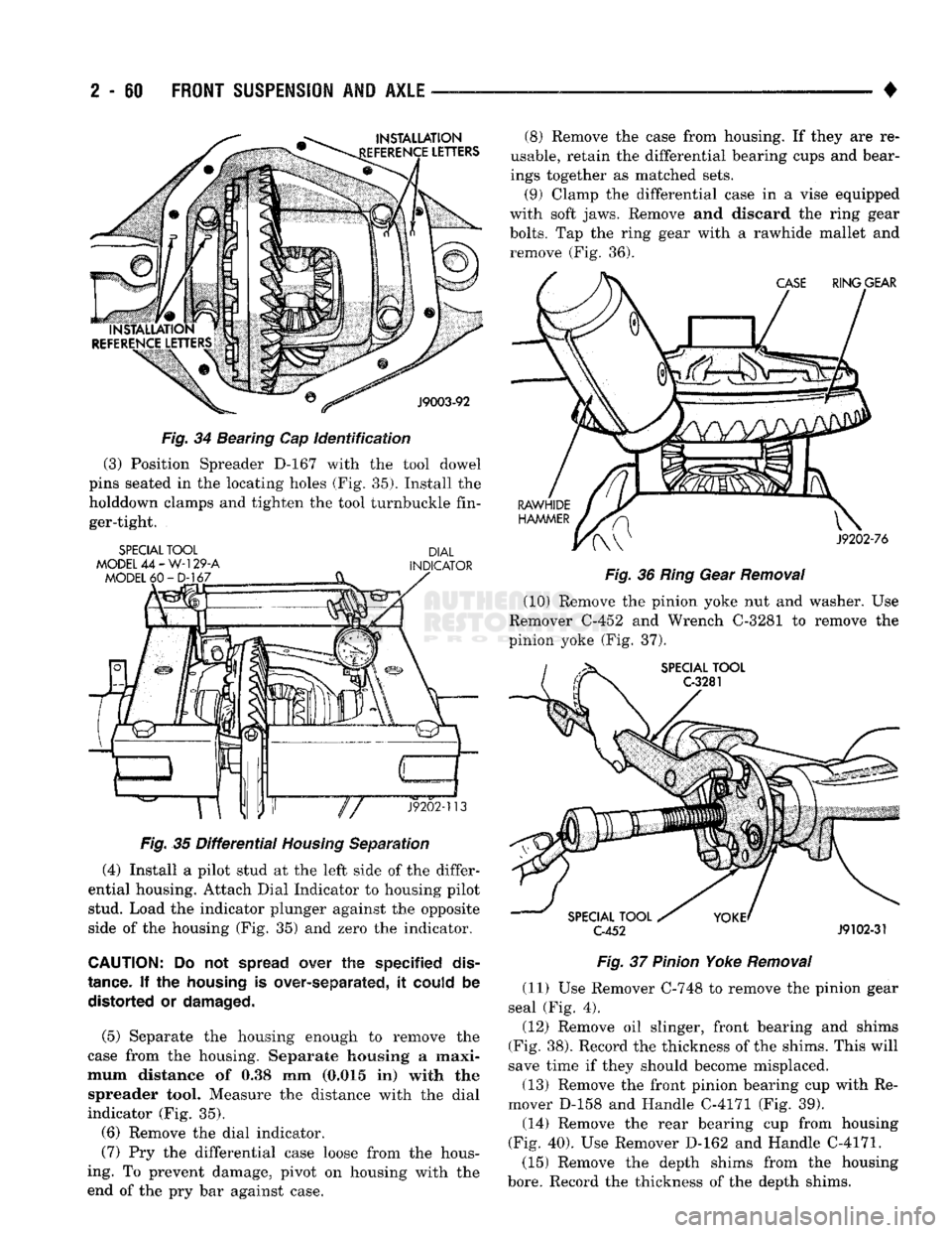
(1) Note the installation reference letters
stamped on the bearing caps and housing ma
chined sealing surface (Fig. 34).
(2) Remove the differential bearing caps.
Page 113 of 1502
2
- 60
FRONT
SUSPENSION
AND
AXLE
•
Fig.
34 Bearing Cap identification (3) Position Spreader D-167 with the tool dowel
pins seated in the locating holes (Fig. 35). Install the
holddown clamps and tighten the tool turnbuckle fin ger-tight.
SPECIAL
TOOL
DIAL
MODEL
44 -
W-129-A
INDICATOR
Fig.
35
Differential
Housing
Separation (4) Install a pilot stud at the left side of the differ
ential housing. Attach Dial Indicator to housing pilot stud. Load the indicator plunger against the opposite
side of the housing (Fig. 35) and zero the indicator.
CAUTION:
Do not
spread
over the specified
dis
tance.
If the
housing
is over-separated, it
could
be distorted or
damaged.
(5) Separate the housing enough to remove the
case from the housing. Separate housing a maxi
mum distance of 0.38 mm (0.015 in) with the spreader tool. Measure the distance with the dial
indicator (Fig. 35).
(6) Remove the dial indicator.
(7) Pry the differential case loose from the hous
ing. To prevent damage, pivot on housing with the
end of the pry bar against case. (8) Remove the case from housing. If they are re
usable, retain the differential bearing cups and bear
ings together as matched sets. (9) Clamp the differential case in a vise equipped
with soft jaws. Remove and discard the ring gear
bolts.
Tap the ring gear with a rawhide mallet and remove (Fig. 36).
Fig.
36
Ring
Gear
Removal
(10) Remove the pinion yoke nut and washer. Use
Remover C-452 and Wrench C-3281 to remove the
pinion yoke (Fig. 37). C-452
J9102-31
Fig.
37
Pinion
Yoke
Removal
(11) Use Remover C-748 to remove the pinion gear
seal (Fig. 4).
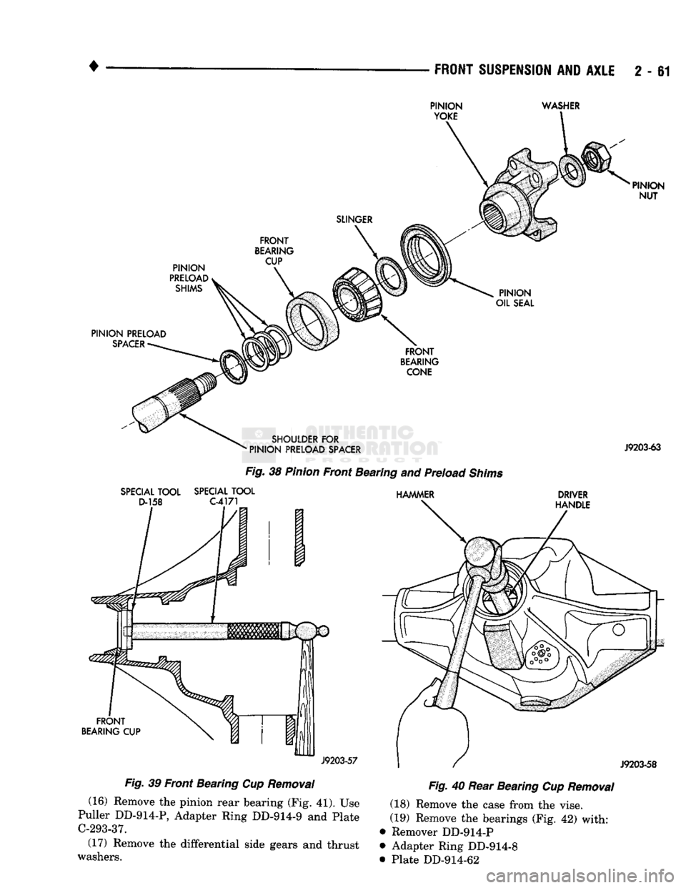
(12) Remove oil slinger, front bearing and shims
(Fig. 38). Record the thickness of the shims. This will
save time if they should become misplaced.
(13) Remove the front pinion bearing cup with Re
mover D-158 and Handle C-4171 (Fig. 39). (14) Remove the rear bearing cup from housing
(Fig. 40). Use Remover D-162 and Handle C-4171.
(15) Remove the depth shims from the housing
bore.
Record the thickness of the depth shims.
Page 114 of 1502
FRONT
SUSPENSION
AND
AXLE
2 - 61
PINION
YOKE
WASHER
SLINGER
PINION
PRELOAD,
SHIMS
FRONT
BEARING
CUP
PINION
NUT
PINION
OIL
SEAL
PINION PRELOAD
SPACER
FRONT
BEARING
CONE
SHOULDER
FOR
•
PINION
PRELOAD
SPACER
J9203-63
SPECIAL
TOOL
SPECIAL
TOOL
D-158
C-4171
Fig.
38
Pinion
Front Bearing and Preload
Shims
HAMMER
DRIVER
HANDLE
FRONT
BEARING
CUP
J9203-57
J9203-58
Fig.
39 Front Bearing Cup
Removal
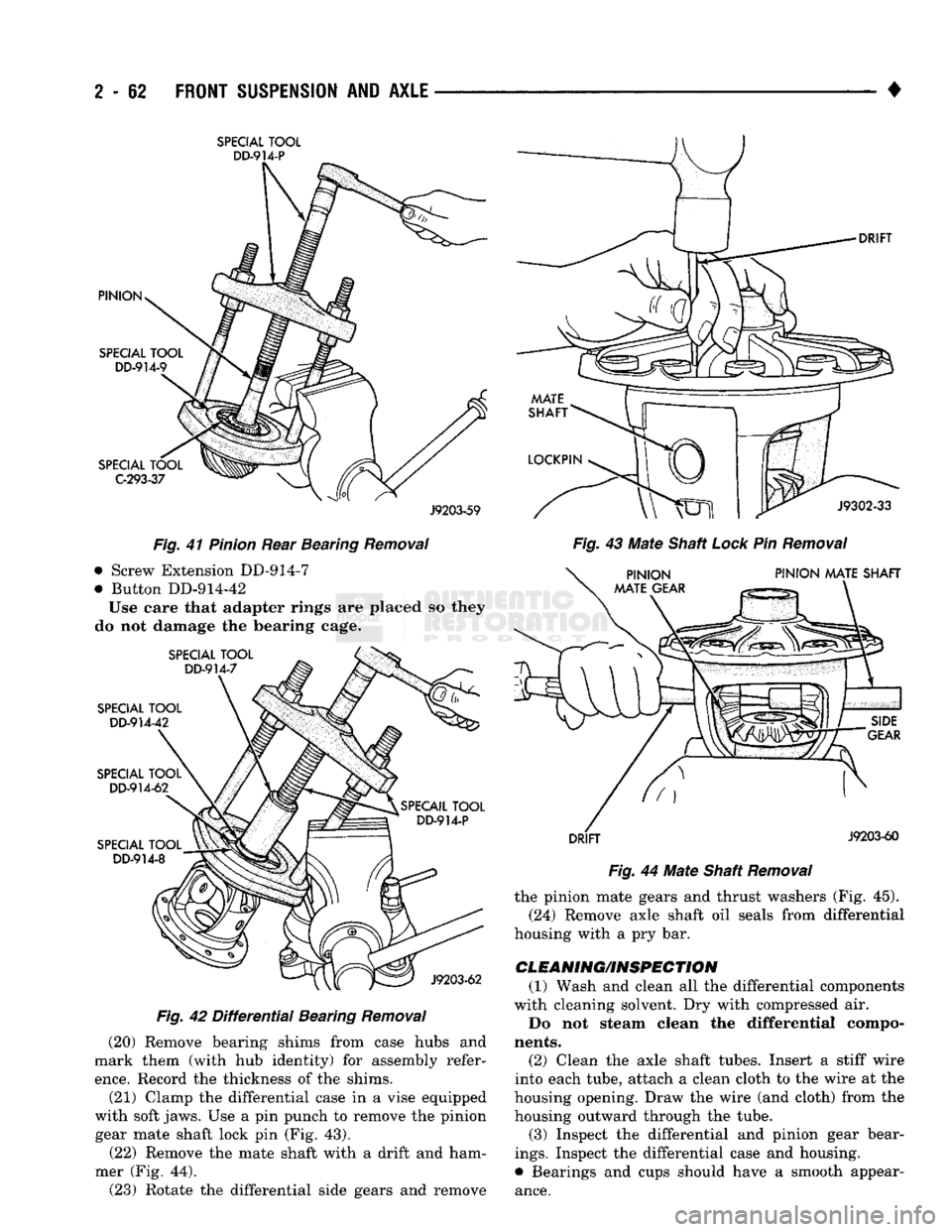
(16) Remove the pinion rear bearing (Fig. 41). Use
Puller DD-914-P, Adapter Ring DD-914-9 and Plate
C-293-37.
(17) Remove the differential side gears and thrust
washers.
Fig.
40 Rear Bearing Cup
Removal
(18) Remove the case from the vise.
(19) Remove the bearings (Fig. 42) with: Remover DD-914-P
Adapter Ring DD-914-8
Plate DD-914-62
Page 115 of 1502
2
- 82
FRONT SUSPENSION
AND
AXLE
•
SPECIAL
TOOL
DD-914-P
J9203-59
Fig.
41
Pinion
Rear Bearing
Removal
• Screw Extension DD-914-7
• Button DD-914-42
Use eare that adapter rings are placed so they
do not damage the bearing cage.
Fig.
42
Differential
Bearing
Removal
(20) Remove bearing shims from case hubs and
mark them (with hub identity) for assembly refer
ence.
Record the thickness of the shims.
(21) Clamp the differential case in a vise equipped
with soft jaws. Use a pin punch to remove the pinion gear mate shaft lock pin (Fig. 43).
(22) Remove the mate shaft with a drift and ham
mer (Fig. 44). (23) Rotate the differential side gears and remove
Fig.
43 Mate Shaft
Lock
Pin
Removal
Fig.
44 Mate Shaft
Removal
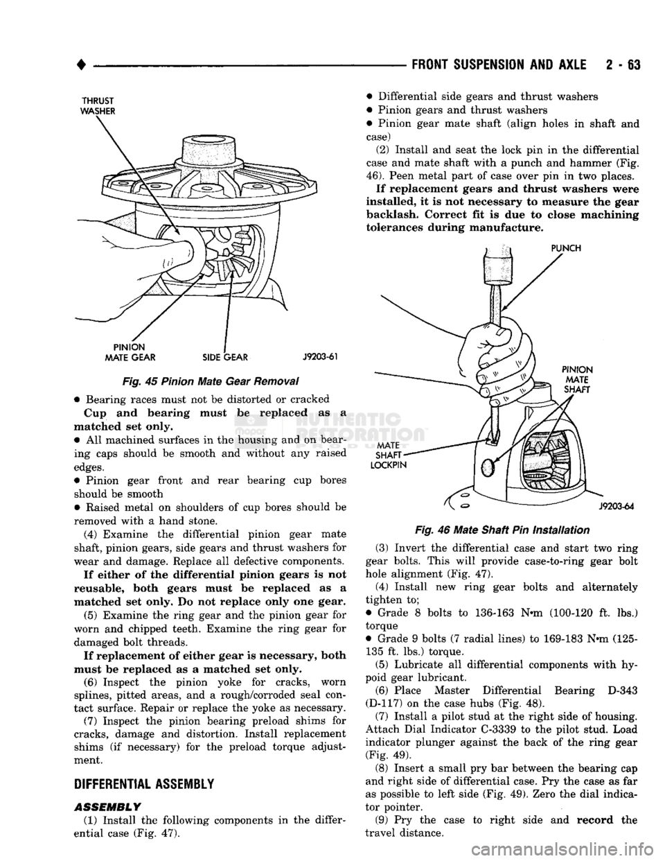
the pinion mate gears and thrust washers (Fig. 45).
(24) Remove axle shaft oil seals from differential
housing with a pry bar.
CLEANING/INSPECTION (1) Wash and clean all the differential components
with cleaning solvent. Dry with compressed air.
Do not steam clean the differential compo
nents.
(2) Clean the axle shaft tubes. Insert a stiff wire
into each tube, attach a clean cloth to the wire at the
housing opening. Draw the wire (and cloth) from the housing outward through the tube.
(3) Inspect the differential and pinion gear bear
ings.
Inspect the differential case and housing.
• Bearings and cups should have a smooth appear
ance.
Page 116 of 1502
•
FRONT SUSPENSION
AND
AXLE
2 - 63
THRUST
WASHER
Fig.
45
Pinion
Mate
Gear
Removal
• Bearing races must not be distorted or cracked
Cup and bearing must be replaced as a
matched set only. • All machined surfaces in the housing and on bear
ing caps should be smooth and without any raised
edges.
• Pinion gear front and rear bearing cup bores should be smooth
• Raised metal on shoulders of cup bores should be
removed with a hand stone.
(4) Examine the differential pinion gear mate
shaft, pinion gears, side gears and thrust washers for
wear and damage. Replace all defective components.
If either of the differential pinion gears is not
reusable, both gears must be replaced as a
matched set only. Do not replace only one gear.
(5) Examine the ring gear and the pinion gear for
worn and chipped teeth. Examine the ring gear for damaged bolt threads.
If replacement of either gear is necessary, both
must be replaced as a matched set only. (6) Inspect the pinion yoke for cracks, worn
splines, pitted areas, and a rough/corroded seal con
tact surface. Repair or replace the yoke as necessary. (7) Inspect the pinion bearing preload shims for
cracks, damage and distortion. Install replacement shims (if necessary) for the preload torque adjust
ment.
DIFFERENTIAL
ASSEMBLY
ASSEMBLY
(1) Install the following components in the differ
ential case (Fig. 47). • Differential side gears and thrust washers
• Pinion gears and thrust washers
• Pinion gear mate shaft (align holes in shaft and
case) (2) Install and seat the lock pin in the differential
case and mate shaft with a punch and hammer (Fig.
46).
Peen metal part of case over pin in two places. If replacement gears and thrust washers were
installed, it is not necessary to measure the gear
backlash. Correct fit is due to close machining tolerances during manufacture.
Fig.
46
Mate
Shaft Pin
Installation
(3) Invert the differential case and start two ring
gear bolts. This will provide case-to-ring gear bolt
hole alignment (Fig. 47). (4) Install new ring gear bolts and alternately
tighten to;
• Grade 8 bolts to 136-163 N*m (100-120 ft. lbs.)
torque
• Grade 9 bolts (7 radial lines) to 169-183 N*m (125- 135 ft. lbs.) torque.
(5) Lubricate all differential components with hy
poid gear lubricant. (6) Place Master Differential Bearing D-343
(D-117) on the case hubs (Fig. 48). (7) Install a pilot stud at the right side of housing.
Attach Dial Indicator C-3339 to the pilot stud. Load indicator plunger against the back of the ring gear (Fig. 49).
(8) Insert a small pry bar between the bearing cap
and right side of differential case. Pry the case as far
as possible to left side (Fig. 49). Zero the dial indica
tor pointer.
(9) Pry the case to right side and record the
travel distance.