1993 DODGE TRUCK wiring diagram
[x] Cancel search: wiring diagramPage 422 of 1502
•
VEHICLE
SPEED
CONTROL SYSTEM
8H - 7
TEST
PROCEDURES
INDEX
page
Checking
for
Diagnostic
Trouble
Code
7
General
Information
7
Inoperative
System
7
Road
Test
7
Speed
Control
Cable Adjustment—Diesel Engine
. 9
Speed
Control
Cable
Attachment
10
GENERAL
INFORMATION
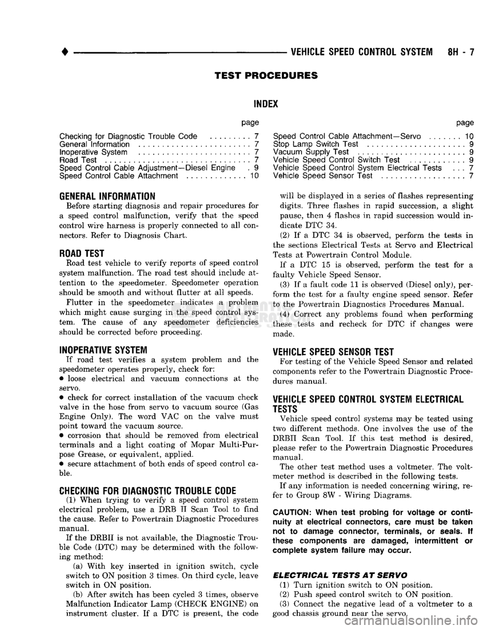
Before starting diagnosis and repair procedures for
a speed control malfunction, verify that the speed
control wire harness is properly connected to all con nectors. Refer to Diagnosis Chart.
ROAD
TEST
Road test vehicle to verify reports of speed control
system malfunction. The road test should include at
tention to the speedometer. Speedometer operation should be smooth and without flutter at all speeds. Flutter in the speedometer indicates a problem
which might cause surging in the speed control sys
tem. The cause of any speedometer deficiencies should be corrected before proceeding.
INOPERATIVE SYSTEM
If road test verifies a system problem and the
speedometer operates properly, check for:
• loose electrical and vacuum connections at the
servo.
• check for correct installation of the vacuum check
valve in the hose from servo to vacuum source (Gas
Engine Only). The word VAC on the valve must
point toward the vacuum source. • corrosion that should be removed from electrical
terminals and a light coating of Mopar Multi-Pur
pose Grease, or equivalent, applied. • secure attachment of both ends of speed control ca
ble.
CHECKING
FOR DIAGNOSTIC TROUBLE CODE
(1) When trying to verify a speed control system
electrical problem, use a DRB II Scan Tool to find
the cause. Refer to Powertrain Diagnostic Procedures manual. If the DRBII is not available, the Diagnostic Trou
ble Code (DTC) may be determined with the follow ing method: (a) With key inserted in ignition switch, cycle
switch to ON position 3 times. On third cycle, leave
switch in ON position. (b) After switch has been cycled 3 times, observe
Malfunction Indicator Lamp (CHECK ENGINE) on instrument cluster. If a DTC is present, the code
page
Speed
Control
Cable Attachment—Servo
10
Stop Lamp Switch Test
9
Vacuum Supply Test
....................... 9
Vehicle Speed
Control
Switch Test
. 9
Vehicle Speed
Control
System
Electrical
Tests
... 7
Vehicle Speed Sensor Test
7
will be displayed in a series of flashes representing
digits.
Three flashes in rapid succession, a slight
pause, then 4 flashes in rapid succession would in dicate DTC 34.
(2) If a DTC 34 is observed, perform the tests in
the sections Electrical Tests at Servo and Electrical
Tests at Powertrain Control Module.
If a DTC 15 is observed, perform the test for a
faulty Vehicle Speed Sensor.
(3) If a fault code 11 is observed (Diesel only), per
form the test for a faulty engine speed sensor. Refer
to the Powertrain Diagnostics Procedures Manual.
(4) Correct any problems found when performing
these tests and recheck for DTC if changes were made.
VEHICLE SPEED SENSOR TEST
For testing of the Vehicle Speed Sensor and related
components refer to the Powertrain Diagnostic Proce
dures manual.
VEHICLE SPEED CONTROL SYSTEM ELECTRICAL
TESTS
Vehicle speed control systems may be tested using
two different methods. One involves the use of the DRBII Scan Tool. If this test method is desired,
please refer to the Powertrain Diagnostic Procedures manual. The other test method uses a voltmeter. The volt
meter method is described in the following tests.
If any information is needed concerning wiring, re
fer to Group 8W - Wiring Diagrams.
CAUTION:
When test probing
for
voltage
or
continuity
at
electrical
connectors, care must
be
taken
not
to
damage connector, terminals,
or
seals.
If
these components
are
damaged,
intermittent
or
complete system
failure
may
occur.
ELECTRICAL
TESTS
AT
SERVO
(1) Turn ignition switch to ON position.
(2) Push speed control switch to ON position.
(3) Connect the negative lead of a voltmeter to a
good chassis ground near the servo.
Page 444 of 1502
•
LAMPS
LAMPS
8L - 1
CONTENTS
page page
BULB
APPLICATION 11 EXTERIOR
LAMPS
SERVICE
PROCEDURES
... 3
EXTERIOR
LAMPS
1 INTERIOR
LAMPS
10
EXTERIOR LAMPS
GENERAL
INFORMATION Each vehicle is equipped with various lamp assem
blies.
A good ground is necessary for proper lighting operation. When changing lamp bulbs check the socket for
corrosion. Clean corrosion with a wire brush. Coat
the inside of the socket lightly with Mopar® Multi- Purpose Grease or equivalent.
DIAGNOSTIC
PROCEDURES
Always begin any diagnosis by testing all of the
fuses and circuit breakers in the system. Refer to Group 8W, Wiring Diagrams. Conventional and halogen headlamps are inter
changeable. It is recommended that they not be in
termixed on a given vehicle.
MULTI-FUNCTION
SWITCH TESTING
PROCEDURES
The multi-function switch contains electrical cir
cuitry for:
• Headlamp Dimmer Switch
• Passing Lights
• Turn Signals
• Hazard Warning • Windshield Wiper
• Pulse Wiper
• Windshield Washer
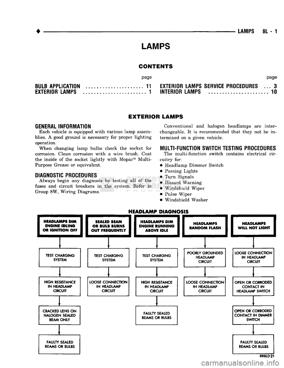
HEADLAMPS
HIM
ENGINE
IDLING
OR
IGNITION
OFF
TEST CHARGING
SYSTEM
HEADLAMP
DIAGNOSIS
SEALED
BEAM
OR
BULB
BURNS
OUT
FREQUENTLY
][
TEST CHARGING SYSTEM
HEADLAMPS
DIM
ENGINE
RUNNING
ABOVE
IDLE
][
TEST CHARGING SYSTEM
HEADLAMPS
RANDOM
FLASH
[
HEADLAMPS
WILL
NOT
LIGHT
POORLY GROUNDED HEADLAMP CIRCUIT
LOOSE
CONNECTION
IN HEADLAMP CIRCUIT
HIGH RESISTANCE IN HEADLAMP CIRCUIT
LOOSE
CONNECTION
IN HEADLAMP CIRCUIT HIGH RESISTANCE
IN HEADLAMP CIRCUIT
LOOSE
CONNECTION
IN HEADLAMP CIRCUIT OPEN OR CORRODED
CONTACT
IN
HEADLAMP SWITCH
CRACKED
LENS ON HALOGEN SEALED BEAM ONLY
FAULTY
SEALED
BEAMS
OR BULBS OPEN OR CORRODED
CONTACT IN DIMMER SWITCH
FAULTY
SEALED
BEAMS
OR BULBS
FAULTY
SEALED
BEAMS
OR BULBS
RR8LD21
Page 457 of 1502
8N
- 2
REAR WINDOW DEFOGGER
• (b) Rear window grid lines (all grid lines would
have to be broken) or one of the feed wires are not
connected for the system to be inoperative.
The following paragraphs outline component check
out procedures.
If turning the switch ON produces severe voltmeter
deflection, the circuit should be closely checked for a shorting condition. If system operation has been verified but indicator
bulb does not light, check and replace bulb.
For detailed wiring information, refer to Group 8W
- Wiring Diagrams.
REAR
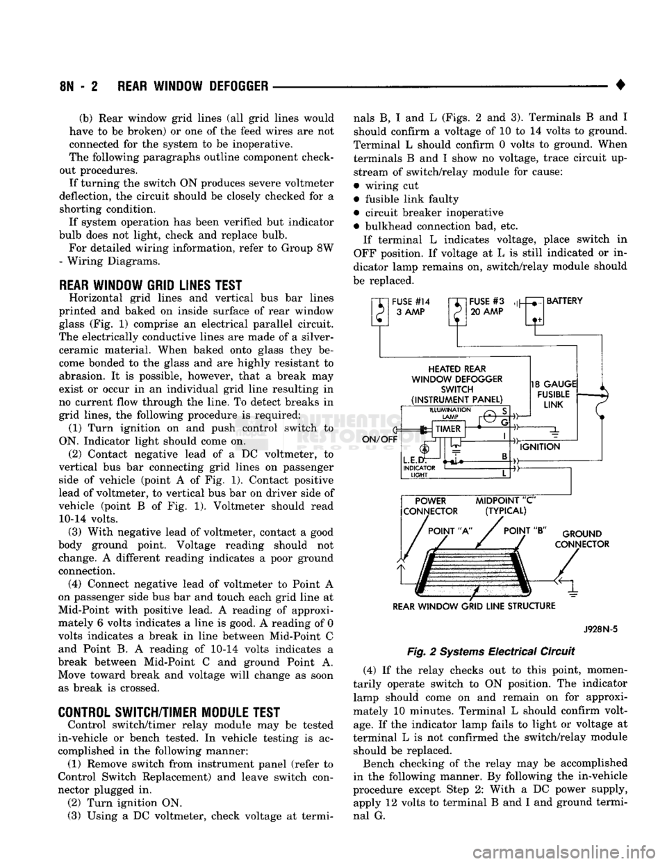
WINDOW GRID LINES TEST
Horizontal grid lines and vertical bus bar lines
printed and baked on inside surface of rear window glass (Fig. 1) comprise an electrical parallel circuit.
The electrically conductive lines are made of a silver- ceramic material. When baked onto glass they be
come bonded to the glass and are highly resistant to abrasion. It is possible, however, that a break may
exist or occur in an individual grid line resulting in
no current flow through the line. To detect breaks in
grid lines, the following procedure is required: (1) Turn ignition on and push control switch to
ON. Indicator light should come on. (2) Contact negative lead of a DC voltmeter, to
vertical bus bar connecting grid lines on passenger side of vehicle (point A of Fig. 1). Contact positive
lead of voltmeter, to vertical bus bar on driver side of
vehicle (point B of Fig. 1). Voltmeter should read 10-14 volts. (3) With negative lead of voltmeter, contact a good
body ground point. Voltage reading should not change. A different reading indicates a poor ground connection. (4) Connect negative lead of voltmeter to Point A
on passenger side bus bar and touch each grid line at
Mid-Point with positive lead. A reading of approxi mately 6 volts indicates a line is good. A reading of 0
volts indicates a break in line between Mid-Point C and Point B. A reading of 10-14 volts indicates a
break between Mid-Point C and ground Point A. Move toward break and voltage will change as soon as break is crossed.
CONTROL SWITCH/TIMER MODULE TEST
Control switch/timer relay module may be tested
in-vehicle or bench tested. In vehicle testing is ac
complished in the following manner: (1) Remove switch from instrument panel (refer to
Control Switch Replacement) and leave switch con
nector plugged in. (2) Turn ignition ON.
(3) Using a DC voltmeter, check voltage at termi nals B, I and L (Figs. 2 and 3). Terminals B and I
should confirm a voltage of 10 to 14 volts to ground.
Terminal L should confirm 0 volts to ground. When terminals B and I show no voltage, trace circuit up
stream of switch/relay module for cause:
• wiring cut
• fusible link faulty
• circuit breaker inoperative
• bulkhead connection bad, etc. If terminal L indicates voltage, place switch in
OFF position. If voltage at L is still indicated or in
dicator lamp remains on, switch/relay module should
be replaced.
"XI
FUSE
#14
rr~
P 3
AAAP
P
FUSE
#3
20
AAAP
BATTERY
HEATED
REAR
WINDOW
DEFOGGER
SWITCH
(INSTRUMENT
PANEL)
ON/OFF
ILLUMINATION
LAMP
fez TIMER
L.E.I
INDICATOR
LIGHT
-©-
18
GAUGE
FUSIBLE
LINK
IGNITION POWER
MIDPOINT
"C"
CONNECTOR (TYPICAL)
POINT
"A"
POINT
"B"
GROUND
CONNECTOR
REAR
WINDOW
GRID
LINE
STRUCTURE
Fig.
2
Systems
Electrical Circuit
J928N-5
(4) If the relay checks out to this point, momen
tarily operate switch to ON position. The indicator lamp should come on and remain on for approxi
mately 10 minutes. Terminal L should confirm volt
age.
If the indicator lamp fails to light or voltage at
terminal L is not confirmed the switch/relay module should be replaced.
Bench checking of the relay may be accomplished
in the following manner. By following the in-vehicle
procedure except Step 2: With a DC power supply, apply 12 volts to terminal B and I and ground termi
nal G.
Page 476 of 1502
•
WIRING DIAGRAMS
8W
- 1
CONTENTS
page page
COMPONENT IDENTIFICATION
.............
9
SPLICE LOCATIONS
29
GENERAL
INFORMATION
1
WIRING DIAGRAMS AD-BODY
37
GENERAL
INFORMATION
INDEX
page
Circuit
Identification
2
Component
Identification
3
Connectors
3
Fusible Links
3
Harness
Repair
3
Locating
A
System
or
Component
2
page
Secondary
Ignition
Wiring
1
Splice Locations
3
Symbols
and
Fuses
5
Troubleshooting
Wiring
Problems
3
Wire Code
Identification
2
Wiring
Diagram Sheets
and
Indexes
1
The wiring diagrams contain
the
latest information
available
at
time
of
publication. Throughout
out
this
group references
may
be
made
to a
particular vehicle
by letter
or
number designation.
A
chart showing
the
breakdown
of
these designations
is
included
in the
Introduction Section
of
this service manual.
SECONDARY
IGNITION WIRING
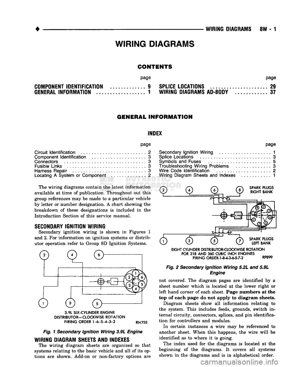
Secondary ignition wiring
is
shown
in
Figures
1
and 2.
For
information
on
ignition systems
or
distrib
utor operation refer
to
Group
8D
Ignition Systems.
SPARK
PLUGS
RIGHT
BANK
3.9L
SIX-CYLINDER
ENGINE
DISTRIBUTOR—CLOCKWISE
ROTATION
FIRING
ORDER
1-6-5-4-3-2
RN755
Fig.
1
Secondary
Ignition Wiring 3.9L
Engine
WIRING DIAGRAM SHEETS AND INDEXES
The wiring diagram sheets
are
organized
so
that
systems relating
to the
basic vehicle
and all of
its op
tions
are
shown. Add-on
or
non-factory options
are
SPARK
PLUGS
LEFT
BANK
EIGHT
CYLINDER
DISTRIBUTOR-CLOCKWISE
ROTATION
FOR
318
AND
360
CUBIC
INCH
ENGINES
FIRING
ORDER-1-8^-3-63-7-2 RP899 Fig.
2
Secondary
Ignition Wiring 5.2L and 5.9L
Engine
not covered.
The
diagram pages
are
identified
by a
sheet number which
is
located
at the
lower right
or
left hand corner
of
each sheet. Page numbers
at the
top
of
each page
do not
apply
to
diagram sheets.
Diagram sheets show
all
information relating
to
the system. This includes feeds, grounds, switch
in
ternal circuity, connectors, splices,
and
pin
identifica
tion
for
controllers
and
modules.
In certain instances
a
wire
may be
referenced
to
another sheet. When this happens,
the
wire will
be
identified
as to
where
it is
going.
The index used
for the
diagrams
is
located
at the
beginning
of the
diagrams.
It
covers
all
systems shown
in the
diagrams
and is in
alphabetical order.
WIRING
DIAGRAMS
Page 477 of 1502
8W
- 2
WIRING
DIAGRAMS
•
WIRE CODE
IDENTIFICATION
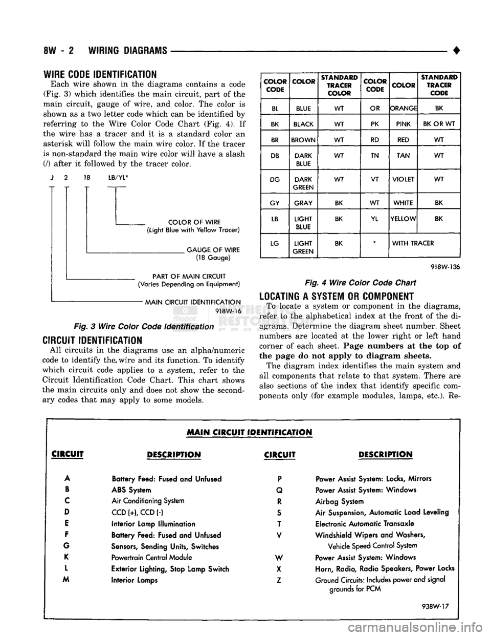
Each wire shown in the diagrams contains a code
(Fig. 3) which identifies the main circuit, part of the
main circuit, gauge of wire, and color. The color is shown as a two letter code which can be identified by
referring to the Wire Color Code Chart (Fig. 4). If
the wire has a tracer and it is a standard color an asterisk will follow the main wire color. If the tracer
is non-standard the main wire color will have a slash (/) after it followed by the tracer color. 18
LB/YL*
COLOR
OF
WIRE
(Light
Blue
with
Yellow
Tracer)
.
GAUGE
OF
WIRE
(18
Gauge)
PART
OF
AAAIN CIRCUIT
(Varies
Depending
on
Equipment)
AAAIN CIRCUIT
IDENTIFICATION
918W-16
Fig.
3
Wire
Color
Code
Identification
CIRCUIT IDENTIFICATION
All circuits in the diagrams use an alpha/numeric
code to identify the, wire and its function. To identify
which circuit code applies to a system, refer to the
Circuit Identification Code Chart. This chart shows
the main circuits only and does not show the second ary codes that may apply to some models.
COLOR
CODE COLOR
STANDARD
TRACER
COLOR COLOR
CODE
COLOR
STANDARD
TRACER
CODE
BL BLUE WT
OR ORANGE
BK
BK
BLACK
WT PK
PINK
BK
OR WT
BR
BROWN
WT RD
RED WT
DB DARK
BLUE WT
TN
TAN WT
DG DARK
GREEN WT
VT
VIOLET
WT
GY GRAY
BK
WT
WHITE
BK
LB
LIGHT
BLUE
BK
YL YELLOW
BK
LG
LIGHT
GREEN
BK
*
WITH
TRACER
918W-136
Fig.
4
Wire
Color
Code
Chart
LOCATING
A
SYSTEM
OR
COMPONENT
To locate a system or component in the diagrams,
refer to the alphabetical index at the front of the di agrams. Determine the diagram sheet number. Sheet
numbers are located at the lower right or left hand
corner of each sheet. Page numbers at the top of
the page do not apply to diagram sheets. The diagram index identifies the main system and
all components that relate to that system. There are
also sections of the index that identify specific com
ponents only (for example modules, lamps, etc.). Re-
MAIN
CIRCUIT IDENTIFICATION
CIRCUIT
DESCRIPTION
CIRCUIT
DESCRIPTION
A
Battery
Feed: Fused and Unfused
P
Power
Assist
System:
Locks,
Mirrors
B
ABS
System Q Power
Assist
System: Windows
C
Air Conditioning System
R
Airbag System
D
CCD
(+),
CCD
(-)
S
Air Suspension, Automatic Load Leveling
E
Interior
Lamp
Illumination
T Electronic Automatic Transaxle
F
Battery
Feed: Fused and Unfused
V
Windshield Wipers and Washers,
G
Sensors,
Sending Units, Switches Vehicle Speed Control System
K
Powertrain
Central
Module W Power
Assist
System: Windows
L
Exterior
Lighting, Stop Lamp Switch
X
Horn, Radio, Radio Speakers, Power Locks
M
Interior
Lamps
Z
Ground Circuits: Includes power and signal
Interior
Lamps
grounds
for PCM
938W-17
Page 478 of 1502
•
WIRING
DIAGRAMS
8W - 3 fer to a components name in the index if you are
unclear as to what a system may be called.
Diagram pages are arranged starting with the bat
tery and fuses. Then working into charging, starting, and ignition systems. After this they start at the
front of the vehicle and work to rear of the vehicle.
The diagrams end with connector identification
pages.
COMPONENT
IDENTIFICATION
To find a components actual location on the vehicle
refer to the wiring and components section index. This section shows the wire harness routing and the compo
nents location in the vehicle. When using this section
refer to the wiring diagrams for the general location of
the component. Then use the component identification index to locate the proper figure number.
SPLICE
LOCATIONS
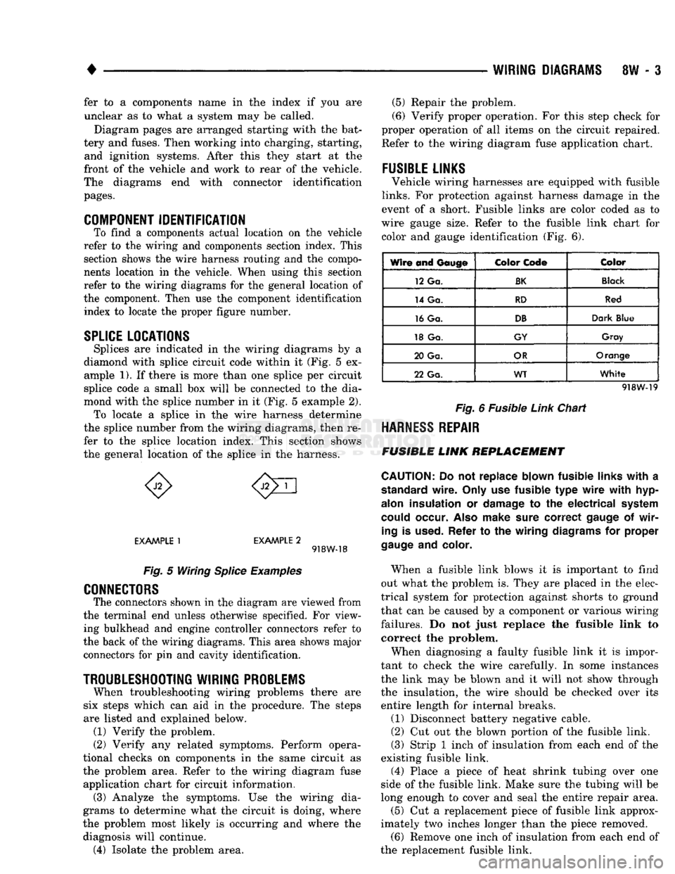
Splices are indicated in the wiring diagrams by a
diamond with splice circuit code within it (Fig. 5 ex ample 1). If there is more than one splice per circuit
splice code a small box will be connected to the dia
mond with the splice number in it (Fig. 5 example 2). To locate a splice in the wire harness determine
the splice number from the wiring diagrams, then re
fer to the splice location index. This section shows
the general location of the splice in the harness.
EXAMPLE
1
EXAMPLE
2 918W-18
Fig.
5 Wiring
Splice
Examples
CONNECTORS
The connectors shown in the diagram are viewed from
the terminal end unless otherwise specified. For view ing bulkhead and engine controller connectors refer to
the back of the wiring diagrams. This area shows major connectors for pin and cavity identification.
TROUBLESHOOTING
WIRING
PROBLEMS
When troubleshooting wiring problems there are
six steps which can aid in the procedure. The steps
are listed and explained below. (1) Verify the problem.
(2) Verify any related symptoms. Perform opera
tional checks on components in the same circuit as the problem area. Refer to the wiring diagram fuse
application chart for circuit information. (3) Analyze the symptoms. Use the wiring dia
grams to determine what the circuit is doing, where
the problem most likely is occurring and where the diagnosis will continue. (4) Isolate the problem area. (5) Repair the problem.
(6) Verify proper operation. For this step check for
proper operation of all items on the circuit repaired. Refer to the wiring diagram fuse application chart.
FUSIBLE
LINKS
Vehicle wiring harnesses are equipped with fusible
links.
For protection against harness damage in the
event of a short. Fusible links are color coded as to
wire gauge size. Refer to the fusible link chart for color and gauge identification (Fig. 6).
Wire and
Gauge
Color
Code
Color
12 Ga.
BK
Black
14 Ga.
RD
Red
16 Ga.
DB
Dark
Blue
18 Ga.
GY
Gray
20 Ga.
OR
Orange
22 Ga.
WT
White
918W-19
Fig.
6 Fusible
Link
Chart
HARNESS
REPAIR
FUSIBLE
LINK
REPLACEMENT
CAUTION:
Do not replace blown fusible
links
with
a
standard
wire.
Only
use fusible type
wire
with
hyp-
alon
insulation or
damage
to the electrical
system
could
occur.
Also
make
sure
correct
gauge
of
wir
ing
is
used.
Refer to the wiring
diagrams
for proper
gauge
and
color.
When a fusible link blows it is important to find
out what the problem is. They are placed in the elec
trical system for protection against shorts to ground
that can be caused by a component or various wiring
failures. Do not just replace the fusible link to correct the problem.
When diagnosing a faulty fusible link it is impor
tant to check the wire carefully. In some instances
the link may be blown and it will not show through the insulation, the wire should be checked over its
entire length for internal breaks.
(1) Disconnect battery negative cable.
(2) Cut out the blown portion of the fusible link.
(3) Strip 1 inch of insulation from each end of the
existing fusible link.
(4) Place a piece of heat shrink tubing over one
side of the fusible link. Make sure the tubing will be
long enough to cover and seal the entire repair area.
(5) Cut a replacement piece of fusible link approx
imately two inches longer than the piece removed. (6) Remove one inch of insulation from each end of
the replacement fusible link.
Page 479 of 1502
8W
- 4
WIRING
DIAGRAMS
(7) Spread
the
strands
of
wire apart
on
each
of the
exposed wires
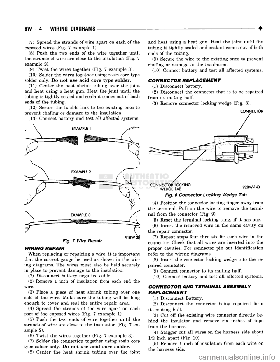
(Fig. 7
example
1).
(8) Push
the two
ends
of the
wire together until
the strands
of
wire
are
close
to the
insulation
(Fig. 7
example
2).
(9) Twist
the
wires together
(Fig. 7
example
3).
(10) Solder
the
wires together using rosin core type
solder only.
Do not use
acid core type solder.
(11) Center
the
heat shrink tubing over
the
joint
and heat using
a
heat
gun.
Heat
the
joint until
the
tubing
is
tightly sealed
and
sealant comes
out of
both ends
of the
tubing. (12) Secure
the
fusible link
to the
existing ones
to
prevent chafing
or
damage
to the
insulation.
(13) Connect battery
and
test
all
affected systems.
Fig.
7
Wire Repair
918W-20
WIRING REPAIR When replacing
or
repairing
a
wire,
it is
important
that
the
correct gauge
be
used
as
shown
in the
wir ing diagrams.
The
wires must also
be
held securely
in place
to
prevent damage
to the
insulation.
(1) Disconnect battery negative cable.
(2) Remove
1
inch
of
insulation from each
end the
wire.
(3) Place
a
piece
of
heat shrink tubing over
one
side
of the
wire. Make sure
the
tubing will
be
long
enough
to
cover
and
seal
the
entire repair area.
(4) Spread
the
strands
of the
wire apart
on
each
part
of the
exposed wires
(Fig. 7
example
1).
(5)
Push
the two
ends
of
wire together until
the
strands
of
wire
are
close
to the
insulation
(Fig. 7 ex
ample
2).
(6) Twist
the
wires together
(Fig. 7
example
3).
(7) Solder
the
connection together using rosin core
type solder only.
Do not use
acid core solder.
(8)
Center
the
heat shrink tubing over
the
joint and heat using
a
heat
gun.
Heat
the
joint until
the
tubing
is
tightly sealed
and
sealant comes
out of
both
ends
of the
tubing.
(9) Secure
the
wire
to the
existing ones
to
prevent
chafing
or
damage
to the
insulation.
(10) Connect battery
and
test
all
affected systems.
CONNECTOR REPLACEMENT (1) Disconnect battery.
(2) Disconnect
the
connector that
is to be
repaired
from
its
mating
half.
(3) Remove connector locking wedge
(Fig. 8).
CONNECTOR
CONNECTOR
LOCKING
WEDGE
TAB
928W-143
Fig.
8
Connector Locking Wedge
Tab
(4) Position
the
connector locking finger away from
the terminal. Pull
on the
wire
to
remove
the
termi nal from
the
connector
(Fig. 9).
(5) Reset
the
terminal locking tang,
if it has one.
(6) Insert
the
removed wire
in the
same cavity
on
the repair connector.
(7) Repeat steps four thru
six for
each wire
in the
connector. Check that
all
wires
are
inserted into
the
proper cavities.
For
connector
pin out
identification refer
to the
wiring diagrams.
(8) Insert
the
connector locking wedge into
the re
paired connector.
(9) Connect connector
to its
mating
half.
(10) Connect battery
and
test
all
affected systems.
CONNECTOR
AND
TERMINAL ASSEMBLY
REPLACEMENT
(1) Disconnect Battery.
(2) Disconnect
the
connector being repaired form
its mating
half.
(3)
Cut off the
existing wire connector directly
be
hind
the
insulator
and
remove
six
inches
of
tape
from
the
harness.
(4) Stagger
cut all
wires
on the
harness side about
1/2
inch apart
(Fig. 10).
(5) Remove
1
inch
of
insulation from each wire
on
the harness side.
Page 480 of 1502
WIRING DIAGRAMS
SW - 5
CONNECTOR
LOCKING WEDGE
CONNECTOR
LOCKING
FINGER
If
928W-144
Fig.
9
Connector
Locking
Finger
and
Locking
Wedge
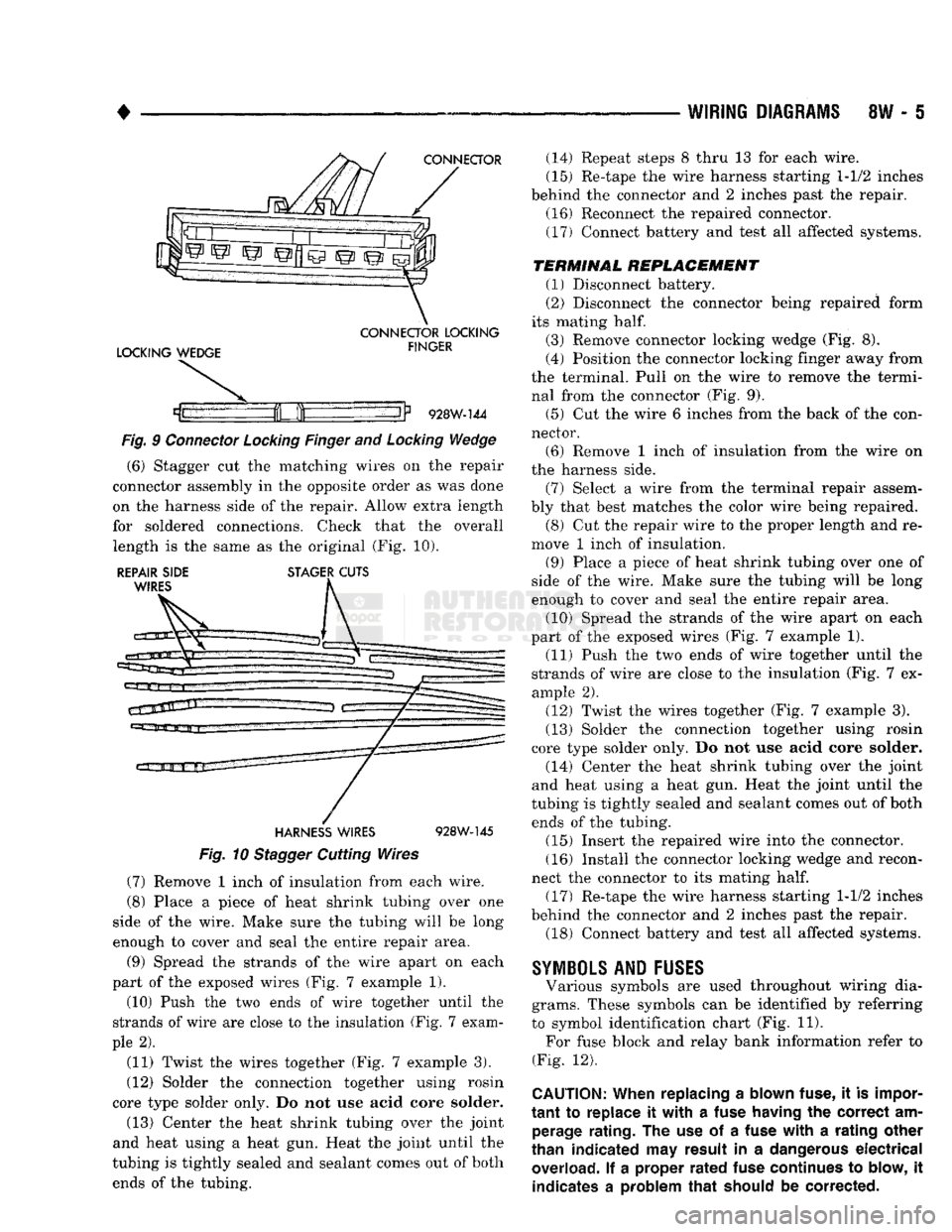
(6) Stagger cut the matching wires on the repair
connector assembly in the opposite order as was done
on the harness side of the repair. Allow extra length
for soldered connections. Check that the overall length is the same as the original (Fig. 10).
REPAIR SIDE STAGER CUTS WIRES
HARNESS
WIRES
928W-145
Fig.
10
Stagger
Cutting Wires (7) Remove 1 inch of insulation from each wire.
(8) Place a piece of heat shrink tubing over one
side of the wire. Make sure the tubing will be long
enough to cover and seal the entire repair area.
(9) Spread the strands of the wire apart on each
part of the exposed wires (Fig. 7 example 1).
(10) Push the two ends of wire together until the
strands of wire are close to the insulation (Fig. 7 exam
ple 2).
(11) Twist the wires together (Fig. 7 example 3).
(12) Solder the connection together using rosin
core type solder only. Do not use acid core solder.
(13) Center the heat shrink tubing over the joint
and heat using a heat gun. Heat the joint until the
tubing is tightly sealed and sealant comes out of both ends of the tubing. (14) Repeat steps 8 thru 13 for each wire.
(15) Re-tape the wire harness starting 1-1/2 inches
behind the connector and 2 inches past the repair. (16) Reconnect the repaired connector.
(17) Connect battery and test all affected systems.
TERMINAL
REPLACEMENT
(1) Disconnect battery.
(2) Disconnect the connector being repaired form
its mating
half.
(3) Remove connector locking wedge (Fig. 8).
(4) Position the connector locking finger away from
the terminal. Pull on the wire to remove the termi nal from the connector (Fig. 9).
(5) Cut the wire 6 inches from the back of the con
nector. (6) Remove 1 inch of insulation from the wire on
the harness side.
(7) Select a wire from the terminal repair assem
bly that best matches the color wire being repaired. (8) Cut the repair wire to the proper length and re
move 1 inch of insulation.
(9) Place a piece of heat shrink tubing over one of
side of the wire. Make sure the tubing will be long
enough to cover and seal the entire repair area.
(10) Spread the strands of the wire apart on each
part of the exposed wires (Fig. 7 example 1). (11) Push the two ends of wire together until the
strands of wire are close to the insulation (Fig. 7 ex
ample 2).
(12) Twist the wires together (Fig. 7 example 3).
(13) Solder the connection together using rosin
core type solder only. Do not use acid core solder.
(14) Center the heat shrink tubing over the joint
and heat using a heat gun. Heat the joint until the
tubing is tightly sealed and sealant comes out of both ends of the tubing.
(15) Insert the repaired wire into the connector.
(16) Install the connector locking wedge and recon
nect the connector to its mating
half.
(17) Re-tape the wire harness starting 1-1/2 inches
behind the connector and 2 inches past the repair. (18) Connect battery and test all affected systems.
SYMBOLS
AND
FUSES
Various symbols are used throughout wiring dia
grams. These symbols can be identified by referring
to symbol identification chart (Fig. 11). For fuse block and relay bank information refer to
(Fig. 12).
CAUTION:
When replacing
a
blown fuse,
it is
impor
tant
to
replace
it
with
a
fuse having
the
correct
am
perage rating.
The use of a
fuse
with
a
rating other
than indicated
may
result
in a
dangerous
electrical
overload.
If a
proper
rated
fuse continues
to
blow,
it
indicates
a
problem
that
should
be
corrected.