1993 CHEVROLET PLYMOUTH ACCLAIM ECU
[x] Cancel search: ECUPage 639 of 2438

(3) Connect electrical lead and rubber hose to pump.
(4) Position reservoir into place and install mount-
ing screws. (5) Fill reservoir.
REAR WASHER RESERVOIR PUMP
REMOVAL
(1) Remove washer reservoir and pump assembly,
refer to Washer Reservoir Removal. (2) With mechanical fingers, loosen pump filter
and nut through liquid filler opening. (3) Disconnect the outside portion of the pump.
(4) Remove inner and outer portions of the pump,
and remove pump.
INSTALLATION (1) Install rubber grommet into place in bottom of
reservoir. (2) Position pump into place, install nut through
filler opening and tighten with mechanical fingers. (3) Install reservoir and pump assembly, refer to
Reservoir Installation.
WASHER NOZZLE
FRONT WASHER NOZZLE
These models are equipped with the washer nozzles
attached to the wiper arms. Each arm emit five streams across the wiper pattern. These washer sys-
tems requires no adjustment. If nozzle performance is
unsatisfactory, they should be replaced. The right
and left nozzles are identical.
REMOVAL To remove unsnap nozzle from wiper arm and dis-
connect hose.
INSTALLATION
To install make sure that both the nozzle and the
hose guard are securely snapped into position.
REAR WASHER NOZZLE
REMOVAL
(1) Pull washer nozzle out of mounting grommet
(Fig. 35). (2) Disconnect hose from nozzle.
INSTALLATION (1) Connect the hose to the nozzle.
(2) Moisten the nozzle and hose.
(3) Insert nozzle into mounting grommet.
(4) Align nozzle.
(5) Open liftgate.
(6) Verify engagement of hose grommets to vehicle
body and liftgate.
Fig. 31 Windshield Washer SystemÐAC and AY Bodies
Ä WINDSHIELD WIPER AND WASHER SYSTEMS 8K - 19
Page 650 of 2438

INSTALLATION
Reverse the preceding operation.
TAIL, STOP AND TURN SIGNAL AND BACK-UP
LAMP
REMOVAL (FIG. 4)
(1) Open deck lid and remove the plastic wing nut
securing the rear trim cover in place. (2) Pivot the end of the trim panel out of the way
to gain access, and remove wing-nuts holding the
lamp to the vehicle. (3) Separate the tail lamp from the body far
enough to rotate the socket and bulb assemblies. Ro-
tate sockets one-half turn and pull the sockets out of
the lamp body. (4) Remove the bulb from the socket.
INSTALLATION
Reverse the preceding operation.
LICENSE PLATE LAMPSÐAA/C Body
REMOVAL (FIG. 5)
(1) Remove screws holding license plate lamp to
rear bumper fascia. (2) Separate license plate lamp from fascia.
(3) Remove socket from license plate lamp.
(4) Pull bulb from socket if bulb replacement is re-
quired.
INSTALLATION
Reverse the preceding operation.
LICENSE PLATE LAMP OR BULBÐAA/P Body
REMOVAL (FIG. 6)
(1) Remove two lamp assembly attaching screws
above the rear license plate opening. (2) Remove the lens from the deck-lid.
(3) Pull the bulb from the socket.
INSTALLATION
Reverse the preceding operation.
Fig. 3 Front Side Marker Lamps
Fig. 4 Rear LightingÐAA/P or AA/D Body
Fig. 5 License Plate LampsÐAA/C Body
Fig. 6 License Plate LampÐAA/P Body
8L - 8 LAMPS Ä
Page 654 of 2438

INSTALLATION
Reverse the preceding operation.
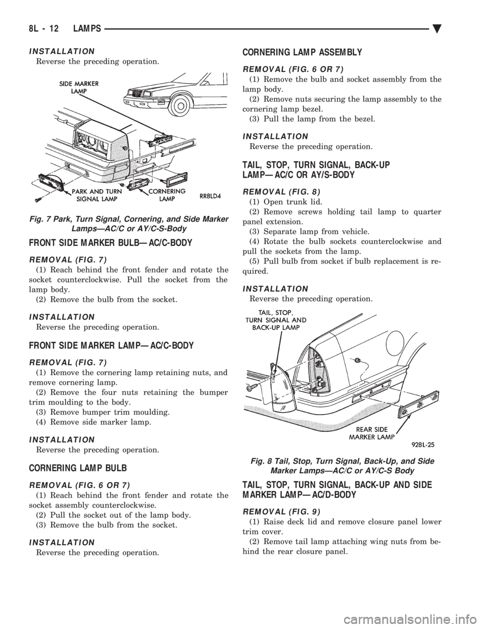
FRONT SIDE MARKER BULBÐAC/C-BODY
REMOVAL (FIG. 7)
(1) Reach behind the front fender and rotate the
socket counterclockwise. Pull the socket from the
lamp body. (2) Remove the bulb from the socket.
INSTALLATION
Reverse the preceding operation.
FRONT SIDE MARKER LAMPÐAC/C-BODY
REMOVAL (FIG. 7)
(1) Remove the cornering lamp retaining nuts, and
remove cornering lamp. (2) Remove the four nuts retaining the bumper
trim moulding to the body. (3) Remove bumper trim moulding.
(4) Remove side marker lamp.
INSTALLATION
Reverse the preceding operation.
CORNERING LAMP BULB
REMOVAL (FIG. 6 OR 7)
(1) Reach behind the front fender and rotate the
socket assembly counterclockwise. (2) Pull the socket out of the lamp body.
(3) Remove the bulb from the socket.
INSTALLATION
Reverse the preceding operation.
CORNERING LAMP ASSEMBLY
REMOVAL (FIG. 6 OR 7)
(1) Remove the bulb and socket assembly from the
lamp body. (2) Remove nuts securing the lamp assembly to the
cornering lamp bezel. (3) Pull the lamp from the bezel.
INSTALLATION
Reverse the preceding operation.
TAIL, STOP, TURN SIGNAL, BACK-UP
LAMPÐAC/C OR AY/S-BODY
REMOVAL (FIG. 8)
(1) Open trunk lid.
(2) Remove screws holding tail lamp to quarter
panel extension. (3) Separate lamp from vehicle.
(4) Rotate the bulb sockets counterclockwise and
pull the sockets from the lamp. (5) Pull bulb from socket if bulb replacement is re-
quired.
INSTALLATION
Reverse the preceding operation.
TAIL, STOP, TURN SIGNAL, BACK-UP AND SIDE
MARKER LAMPÐAC/D-BODY
REMOVAL (FIG. 9)
(1) Raise deck lid and remove closure panel lower
trim cover. (2) Remove tail lamp attaching wing nuts from be-
hind the rear closure panel.
Fig. 7 Park, Turn Signal, Cornering, and Side Marker LampsÐAC/C or AY/C-S-Body
Fig. 8 Tail, Stop, Turn Signal, Back-Up, and SideMarker LampsÐAC/C or AY/C-S Body
8L - 12 LAMPS Ä
Page 659 of 2438

TAIL, STOP, TURN SIGNAL BULB OR LAMP
REMOVAL (FIG. 3)
(1) Open deck lid and remove the plastic wing nut
securing the rear trim cover in place. (2) Pivot the end of the trim panel out of the way
to gain access, and remove three plastic wing-nuts
securing the lamp to the vehicle. (3) Separate the tail lamp from the body far
enough to rotate the socket and bulb assemblies
counterclockwise one-half turn and pull the sockets
out of the lamp body. (4) Remove the bulb from socket.
INSTALLATION
Reverse the preceding operation.
TRUNK LID TAIL LAMP BULB
REMOVAL (FIG. 3)
(1) Remove deck lid liner as necessary. Through
access hole in the inner deck lid, rotate socket coun-
terclockwise one-half turn, and pull the socket and
bulb assembly from the lamp body. (2) Remove the bulb from the socket.
INSTALLATION
Reverse the preceding operation.
TRUNK LID TAIL LAMP
REMOVAL (FIG. 3)
(1) Remove bulb and sockets from trunk lid tail
lamp. (2) Remove six nuts and four screws securing the
tail lamp to the deck lid and remove the lamp assem-
bly from the vehicle.
INSTALLATION
Reverse the preceding operation.
BACK-UP LAMP BULB
REMOVAL (FIG. 3)
(1) From behind the rear bumper fascia, rotate the
bulb and socket assembly counterclockwise one-half
turn and pull the bulb and socket out of the lamp body.
(2) Remove the bulb from the socket.
INSTALLATION
Reverse the preceding operation.
BACK-UP LAMP
REMOVAL (FIG. 3)
(1) Remove the socket and bulb assembly from the
lamp body. (2) Remove two screws from the lamp and pull the
lamp from the rear bumper fascia.
INSTALLATION
Reverse the preceding operation.
REAR SIDE MARKER LAMP BULB
REMOVAL (FIG. 3)
(1) Open the deck lid and remove the fastener
(wing nut) from the lower rear trim panel. Rotate the
inner quarter trim panel forward to gain access to
the lamp assembly. Rotate counterclockwise one-half
turn, and pull the socket and bulb from the lamp
body. (2) Remove the bulb from the socket.
INSTALLATION
Reverse the preceding operation.
REAR SIDE MARKER LAMP
REMOVAL (FIG. 3)
(1) Remove the socket and bulb assembly.
(2) Remove two attaching nuts from the lamp be-
hind the quarter panel and remove the lamp from
the vehicle.
INSTALLATION
Reverse the preceding operation.
LICENSE PLATE LAMP OR BULB
REMOVAL (FIG. 3)
(1) Remove screws holding license plate lamp to
rear bumper fascia.
Fig. 2 Park, Turn Signal, Cornering and Side Marker LampÐTypical
Fig. 3 Tail, Stop, Turn Signal, Back-Up, LicensePlate and Side Marker Lamps
Ä LAMPS 8L - 17
Page 689 of 2438

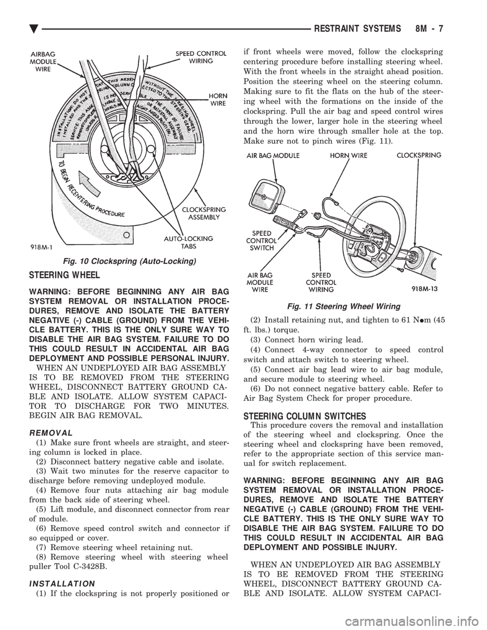
STEERING WHEEL
WARNING: BEFORE BEGINNING ANY AIR BAG
SYSTEM REMOVAL OR INSTALLATION PROCE-
DURES, REMOVE AND ISOLATE THE BATTERY
NEGATIVE (-) CABLE (GROUND) FROM THE VEHI-
CLE BATTERY. THIS IS THE ONLY SURE WAY TO
DISABLE THE AIR BAG SYSTEM. FAILURE TO DO
THIS COULD RESULT IN ACCIDENTAL AIR BAG
DEPLOYMENT AND POSSIBLE PERSONAL INJURY. WHEN AN UNDEPLOYED AIR BAG ASSEMBLY
IS TO BE REMOVED FROM THE STEERING
WHEEL, DISCONNECT BATTERY GROUND CA-
BLE AND ISOLATE. ALLOW SYSTEM CAPACI-
TOR TO DISCHARGE FOR TWO MINUTES.
BEGIN AIR BAG REMOVAL.
REMOVAL
(1) Make sure front wheels are straight, and steer-
ing column is locked in place. (2) Disconnect battery negative cable and isolate.
(3) Wait two minutes for the reserve capacitor to
discharge before removing undeployed module. (4) Remove four nuts attaching air bag module
from the back side of steering wheel. (5) Lift module, and disconnect connector from rear
of module. (6) Remove speed control switch and connector if
so equipped or cover. (7) Remove steering wheel retaining nut.
(8) Remove steering wheel with steering wheel
puller Tool C-3428B.
INSTALLATION
(1) If the clockspring is not properly positioned or if front wheels were moved, follow the clockspring
centering procedure before installing steering wheel.
With the front wheels in the straight ahead position.
Position the steering wheel on the steering column.
Making sure to fit the flats on the hub of the steer-
ing wheel with the formations on the inside of the
clockspring. Pull the air bag and speed control wires
through the lower, larger hole in the steering wheel
and the horn wire through smaller hole at the top.
Make sure not to pinch wires (Fig. 11).
(2) Install retaining nut, and tighten to 61 N Im (45
ft. lbs.) torque. (3) Connect horn wiring lead.
(4) Connect 4-way connector to speed control
switch and attach switch to steering wheel. (5) Connect air bag lead wire to air bag module,
and secure module to steering wheel. (6) Do not connect negative battery cable. Refer to
Air Bag System Check for proper procedure.
STEERING COLUMN SWITCHES
This procedure covers the removal and installation
of the steering wheel and clockspring. Once the
steering wheel and clockspring have been removed,
refer to the appropriate section of this service man-
ual for switch replacement.
WARNING: BEFORE BEGINNING ANY AIR BAG
SYSTEM REMOVAL OR INSTALLATION PROCE-
DURES, REMOVE AND ISOLATE THE BATTERY
NEGATIVE (-) CABLE (GROUND) FROM THE VEHI-
CLE BATTERY. THIS IS THE ONLY SURE WAY TO
DISABLE THE AIR BAG SYSTEM. FAILURE TO DO
THIS COULD RESULT IN ACCIDENTAL AIR BAG
DEPLOYMENT AND POSSIBLE INJURY.
WHEN AN UNDEPLOYED AIR BAG ASSEMBLY
IS TO BE REMOVED FROM THE STEERING
WHEEL, DISCONNECT BATTERY GROUND CA-
BLE AND ISOLATE. ALLOW SYSTEM CAPACI-
Fig. 10 Clockspring (Auto-Locking)
Fig. 11 Steering Wheel Wiring
Ä RESTRAINT SYSTEMS 8M - 7
Page 692 of 2438

(6) Steps (3, 4 or 5) above will confirm system op-
eration. Indicator light illumination means that
there is power available at the output of the relay
only, and does not necessarily verify system opera-
tion. (7) If turning the switch ON produced no distinct
current draw on the ammeter the problem should be
isolated in the following manner: (a) Confirm the ignition switch is ON.
(b) Ensure that the heated rear glass feed wire is
connected to the terminal or pigtail and that the
ground wire is in fact grounded. (c) Ensure that the fusible link and control cir-
cuit fuse is operational and all electrical connec-
tions are secure.
(8) When the above steps have been completed and
the system is still inoperative, one or more of the fol-
lowing is defective: (a) Control switch/timer relay module.
(b) All rear window grid lines would have to be
broken or one of the feed wires are not connected
for the system to be inoperative.
(9) If turning the switch ON produces severe volt-
meter deflection, the circuit should be closely
checked for a shorting condition. (10) If the system operation has been verified but
indicator lamp does not light, replace the switch. (11) For detailed wiring information, refer to group
8W, Wiring Diagrams.
GRID TEST
The horizontal grid lines and vertical bus bar lines
printed and fired on inside surface of rear window
glass (Fig. 2) comprise an electrical parallel circuit.
The electrically conductive lines are composed of a
silver-ceramic material which when fired on glass be-
comes bonded to the glass and is highly resistant to
abrasion. It is possible, however, that a break may
occur in an individual grid line resulting in no cur-
rent flow through the line. To detect breaks in grid
lines the following procedure is required: (1) Turn ignition ON and turn control switch to
ON. The indicator light should come on. (2) Using a DC voltmeter with 0-15 volt range,
contact terminal B with negative lead of voltmeter.
With positive lead of voltmeter, contact terminal A
(Fig. 2). The voltmeter should read 10-14 volts. A
lower voltage reading indicates a poor ground con-
nection. (3) With negative lead of voltmeter, contact a good
body ground point. The voltage reading should not
change. (4) Connect negative lead of voltmeter to terminal
B and touch each grid line at Mid-Point with Posi-
tive lead. A reading of approximately 6 volts indi-
cates a line is good. A reading of 0 volts indicates a
break in line between Mid-Point C and terminal A.
A reading of 10-14 volts indicates a break between Mid-Point C and terminal B. Move toward break and
voltage will change as soon as break is crossed (Figs.
2 and 3).
CONTROL SWITCH/TIMER RELAY MODULE TEST
Control switch/timer relay module may be tested
in-vehicle or bench tested. In vehicle testing is ac-
complished in the following manner: (1) Remove the switch, relay assembly from the in-
strument panel or console, see Group 8E, Instrument
Panel and leave the switch connector plugged in. (2) Turn ignition ON.
(3) Using a DC voltmeter, with 0-15 range, check
voltage at terminals B, I and L. (Figs. 3 and 4). Ter-
minals B and I should confirm a voltage of 10 to 14
volts to ground when the ON switch is pressed. Ter-
minal L should confirm voltage to ground. When ter-
minals B and I show no voltage, trace circuit
upstream of switch/relay module for problem (wiring
cut, fusible link or circuit breaker inoperative, bulk-
head connector not operative, etc.) If terminal L in-
dicates voltage, place switch in Off position. If
voltage at L is still indicated or indicator lamp re-
mains on, the switch/relay module should be re-
placed. (4) If the relay checks out to this point, momen-
tarily operate switch to ON position. The indicator
lamp should come on and remain on for approxi-
mately 10 minutes. Terminal L should confirm volt-
age. If the indicator lamp fails to light or voltage at
terminal L is not confirmed the switch/relay module
should be replaced.
Fig. 3 Systems Electrical Circuit
8N - 2 REAR WINDOW DEFOGGER Ä
Page 696 of 2438

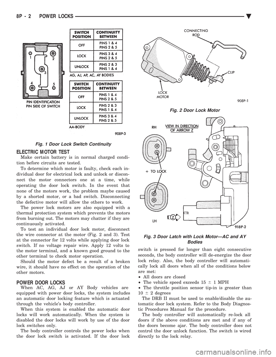
ELECTRIC MOTOR TEST
Make certain battery is in normal charged condi-
tion before circuits are tested. To determine which motor is faulty, check each in-
dividual door for electrical lock and unlock or discon-
nect the motor connectors one at a time, while
operating the door lock switch. In the event that
none of the motors work, the problem maybe caused
by a shorted motor, or a bad switch. Disconnecting
the defective motor will allow the others to work. The power lock motors are also equipped with a
thermal protection system which prevents the motors
from burning out. The motors may chatter if they are
continuously activated. To test an individual door lock motor, disconnect
the wire connector at the motor (Fig. 2 and 3). Test
at the connector for 12 volts while applying door lock
switch. If no voltage repair wire. Apply 12 volts to
the motor terminal, and a known good ground to the
other terminal to check motor operation. Should the motor defect be a result of a broken
wire, it should have no effect on the operation of the
other motors.
POWER DOOR LOCKS
When AC, AG, AJ or AY Body vehicles are
equipped with power door locks, the system includes
an automatic door locking feature which is actuated
through the vehicle's body controller. When this system is enabled the automatic door
locks will work automatically. When the system is
disabled the door locks will work by use of the door
lock switches only. The body controller controls the power locks when
the door lock switch is activated. If the door lock switch is pressed for longer than eight consecutive
seconds, the body controller will de-energize the door
lock relay. Also, the body controller will automati-
cally lock all doors when all of the conditions below
are met:
² All doors are closed
² The vehicle speed exceeds 15 61 MPH
² The throttle position sensor tip-in is greater than
10 62 degrees
The DRB II must be used to enable/disable the au-
tomatic door lock system. Refer to the Body Diagnos-
tic Procedures Manual for the procedure. The body controller will automatically re-lock all
doors if the above conditions are met and if any of
the doors become ajar. The body controller does not
control the door unlock function. The switch is wired
directly to the lock relay.
Fig. 1 Door Lock Switch Continuity
Fig. 2 Door Lock Motor
Fig. 3 Door Latch with Lock MotorÐAC and AY Bodies
8P - 2 POWER LOCKS Ä
Page 699 of 2438

to the deck lid open position. If the pull down limit
switch is depressed at this time, the motor should
stop.(c) If these results are not obtained, replace the
pull down motor assembly.
REMOTE KEYLESS ENTRY
OPERATION
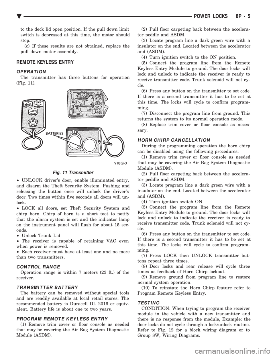
The transmitter has three buttons for operation
(Fig. 11).
² UNLOCK driver's door, enable illuminated entry,
and disarm the Theft Security System. Pushing and
releasing the button once will unlock the driver's
door. Two times within five seconds all doors will un-
lock.
² LOCK all doors, set Theft Security System and
chirp horn. Chirp of horn is a short toot to notify
that the alarm system is set and the indicator lamp
on the instrument panel will flash for about 15 sec-
onds.
² Unlock Trunk Lid
² The receiver is capable of retaining VAC even
when power is removed.
² Each receiver must have at least one and no more
than two transmitters.
CONTROL RANGE
Operation range is within 7 meters (23 ft.) of the
receiver.
TRANSMITTER BATTERY
The battery can be removed without special tools
and are readily available at local retail stores. The
recommended battery is Duracell DL 2016 or equiv-
alent. Battery life is about one to two years.
PROGRAM REMOTE KEYLESS ENTRY
(1) Remove trim cover or floor console as needed
that may be covering the Air Bag System Diagnostic
Module (ASDM). (2) Pull floor carpeting back between the accelera-
tor peddle and ASDM. (3) Locate program line a dark green wire with a
insulator on the end. Located between the accelerator
and (ASDM). (4) Turn ignition switch to the ON position.
(5) Connect the program line from the Remote
Keyless Entry Module to ground. The door locks will
lock and unlock to indicate the receiver is ready to
receive transmitter code. Trunk solenoid will not cy-
cle. (6) Press any button on the transmitter to set code.
If there is a second transmitter it has to be set at
this time. The locks will cycle to confirm program-
ming. (7) Disconnect the program line from ground. This
returns the system to its normal operation mode. (8) Replace trim cover or floor console as neces-
sary.
HORN CHIRP CANCELLATION
During the programming operation the horn chirp
can be disabled using the following procedures: (1) Remove trim cover or floor console as needed
that may be covering the Air Bag System Diagnostic
Module (ASDM). (2) Pull floor carpeting back between the accelera-
tor peddle and ASDM. (3) Locate program line a dark green wire with a
insulator on the end. Located between the accelerator
and (ASDM). (4) Turn ignition switch ON.
(5) Connect the program line from the Remote
Keyless Entry Module to ground. The door locks will
lock and unlock to indicate the receiver is ready to
receive transmitter code. Trunk solenoid will not cy-
cle. (6) Press any button on the transmitter to set code.
If there is a second transmitter it has to be set at
this time. The locks will cycle to confirm program-
ming. (7) Press LOCK then UNLOCK transmitter but-
tons repeat three times. (8) Door locks and rear release will cycle three
times as feedback of Horn Chirp lockout. (9) Remove ground from program line to restore
normal system operation. (10) To reinstate the Horn Chirp feature refer to
Program Remote Keyless Entry.
TESTING
CONDITION: When trying to program the receiver
module in the vehicle with a new transmitter and
there is no response from the module, Example: the
door locks do not cycle through a lock/unlock routine.
Refer to Fig. 12 for a block wiring diagram or to
Group 8W, Wiring Diagrams.
Fig. 11 Transmitter
Ä POWER LOCKS 8P - 5