1993 CHEVROLET PLYMOUTH ACCLAIM ECU
[x] Cancel search: ECUPage 564 of 2438
(2) Pry cover up and forward until released from
instrument panel pad. (3) Lift top cover upward and rearward to remove
from vehicle. (4) For installation place top cover on panel open-
ing. Be certain that blades of top cover are located in
the retaining spring clips. (5) Push forward and down to engage in pad.
INSTRUMENT PANEL REPLACEMENT
CAUTION: Disconnect negative battery cable, in en-
gine compartment, before servicing instrument
panel.
(1) Remove windshield wiper arms.
(2) Open hood and remove cowl top plastic cover.
(3) Remove windshield washer reservoir.
(4) Pull connector loose from the A/C resistor block
and push wiring and grommet through bulkhead into
passenger compartment. (5) Remove the console/consolette assembly.
(6) Remove the passive restraint seat belt logic
control module wiring. (7) Remove six attaching nuts securing the instru-
ment panel to console support brace. (8) Remove the instrument panel to console sup-
port brace with the Air Bag System Diagnostic Mod-
ule attached. (9) Remove right and left cowl side and scuff plate
trim moldings. (10) Remove left and right A-pillar trim moldings.
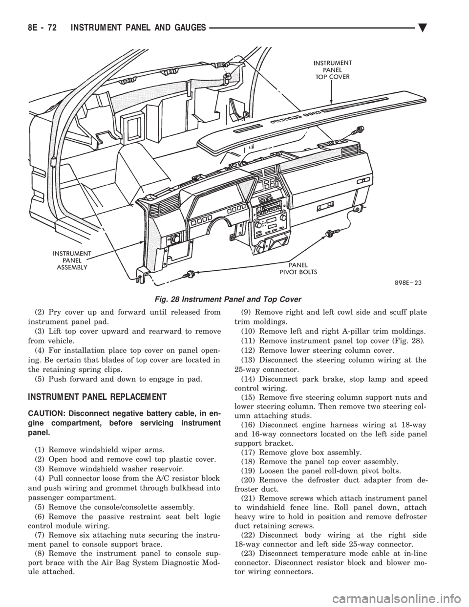
(11) Remove instrument panel top cover (Fig. 28).
(12) Remove lower steering column cover.
(13) Disconnect the steering column wiring at the
25-way connector. (14) Disconnect park brake, stop lamp and speed
control wiring. (15) Remove five steering column support nuts and
lower steering column. Then remove two steering col-
umn attaching studs. (16) Disconnect engine harness wiring at 18-way
and 16-way connectors located on the left side panel
support bracket. (17) Remove glove box assembly.
(18) Remove the panel top cover assembly.
(19) Loosen the panel roll-down pivot bolts.
(20) Remove the defroster duct adapter from de-
froster duct. (21) Remove screws which attach instrument panel
to windshield fence line. Roll panel down, attach
heavy wire to hold in position and remove defroster
duct retaining screws. (22) Disconnect body wiring at the right side
18-way connector and left side 25-way connector. (23) Disconnect temperature mode cable at in-line
connector. Disconnect resistor block and blower mo-
tor wiring connectors.
Fig. 28 Instrument Panel and Top Cover
8E - 72 INSTRUMENT PANEL AND GAUGES Ä
Page 567 of 2438
AUDIO SYSTEM
CONTENTS
page page
ANTENNAS ............................ 20
COMPACT DISC PLAYER ................. 30 RADIOS
................................ 1
SPEAKERS ............................ 24
RADIOS INDEX
page page
Audio Diagnostic Test Procedures ............. 1
Description .............................. 1
Interference Elimination ..................... 1
Radio Removal AP Body Replacement ........ 19 Radio RemovalÐAA Body
.................. 18
Radio RemovalÐAC and AY Bodies .......... 18
Radio RemovalÐAG and AJ Bodies .......... 18
DESCRIPTION
For operation of the factory installed standard and
optional radios and the optional compact disc player,
refer to the Sound Systems Operating Instructions
Manual supplied with the vehicle. All vehicles are equipped with an Ignition-Off
Draw Connector which, is used when the vehicles are
originally shipped from the factory. This connector
which, is located near the battery, helps to prevent
battery discharge during storage. For specific connec-
tor type and location, refer to Group 8W, Wiring Di-
agrams. This connector is included in the radio memory cir-
cuitry and should be checked if the memory of time
or radio station programming is inoperative.
INTERFERENCE ELIMINATION
Some components are used on vehicles equipped
with a radio capacitor, to suppress radio frequency
interference/static. Capacitors are mounted in various locations, on the
generator either internal or external, internal to the
instrument cluster, and internal to the windshield
wiper motor. Ground straps are mounted from radio chassis to
instrument panel support structure, engine to cowl,
across engine mount on right hand side. On vehicles
with air conditioning there is a strap from evapora-
tor valve to cowl. These ground straps should be se-
curely tightened to assure good metal to metal
contact. Ground straps conduct very small high fre-
quency electrical signals to ground and require clean
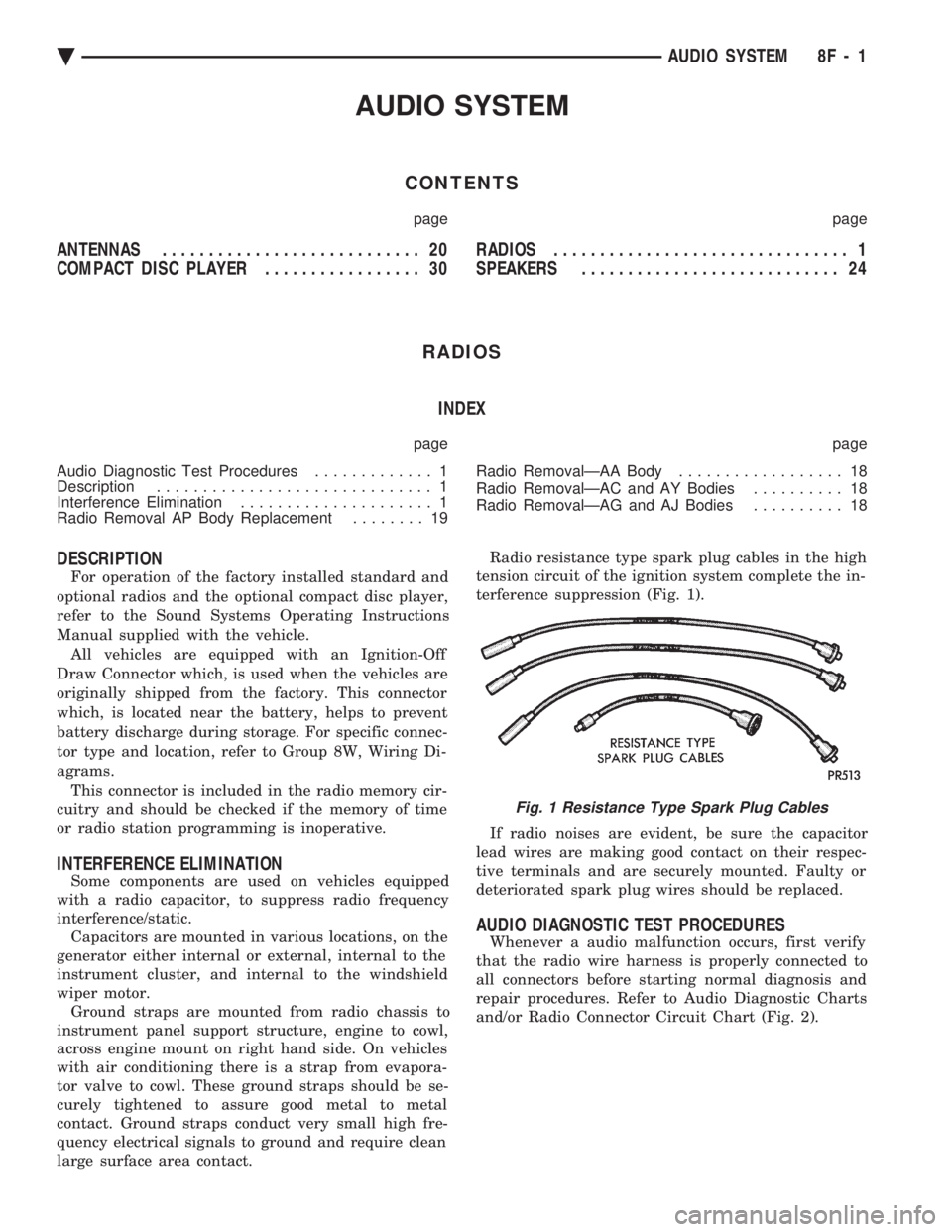
large surface area contact. Radio resistance type spark plug cables in the high
tension circuit of the ignition system complete the in-
terference suppression (Fig. 1).
If radio noises are evident, be sure the capacitor
lead wires are making good contact on their respec-
tive terminals and are securely mounted. Faulty or
deteriorated spark plug wires should be replaced.
AUDIO DIAGNOSTIC TEST PROCEDURES
Whenever a audio malfunction occurs, first verify
that the radio wire harness is properly connected to
all connectors before starting normal diagnosis and
repair procedures. Refer to Audio Diagnostic Charts
and/or Radio Connector Circuit Chart (Fig. 2).
Fig. 1 Resistance Type Spark Plug Cables
Ä AUDIO SYSTEM 8F - 1
Page 584 of 2438
RADIO REMOVALÐAA BODY
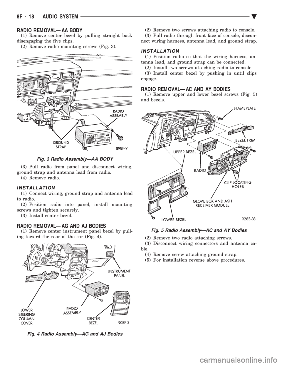
(1) Remove center bezel by pulling straight back
disengaging the five clips. (2) Remove radio mounting screws (Fig. 3).
(3) Pull radio from panel and disconnect wiring,
ground strap and antenna lead from radio. (4) Remove radio.
INSTALLATION
(1) Connect wiring, ground strap and antenna lead
to radio. (2) Position radio into panel, install mounting
screws and tighten securely. (3) Install center bezel.
RADIO REMOVALÐAG AND AJ BODIES
(1) Remove center instrument panel bezel by pull-
ing toward the rear of the car (Fig. 4). (2) Remove two screws attaching radio to console.
(3) Pull radio through front face of console, discon-
nect wiring harness, antenna lead, and ground strap.
INSTALLATION
(1) Position radio so that the wiring harness, an-
tenna lead, and ground strap can be connected. (2) Install two screws attaching radio to console.
(3) Install center bezel by pushing in until clips
engage.
RADIO REMOVALÐAC AND AY BODIES
(1) Remove upper and lower bezel screws (Fig. 5)
and bezels.
(2) Remove two radio attaching screws.
(3) Disconnect wiring connectors and antenna ca-
ble. (4) Remove screw attaching ground strap.
(5) For installation reverse above procedures.
Fig. 3 Radio AssemblyÐAA BODY
Fig. 4 Radio AssemblyÐAG and AJ Bodies
Fig. 5 Radio AssemblyÐAC and AY Bodies
8F - 18 AUDIO SYSTEM Ä
Page 605 of 2438
INOPERATIVE SYSTEM
If road test verifies an inoperative system with a
correct speedometer operation:
² Inspect fuse
² Check for loose electrical and vacuum connections
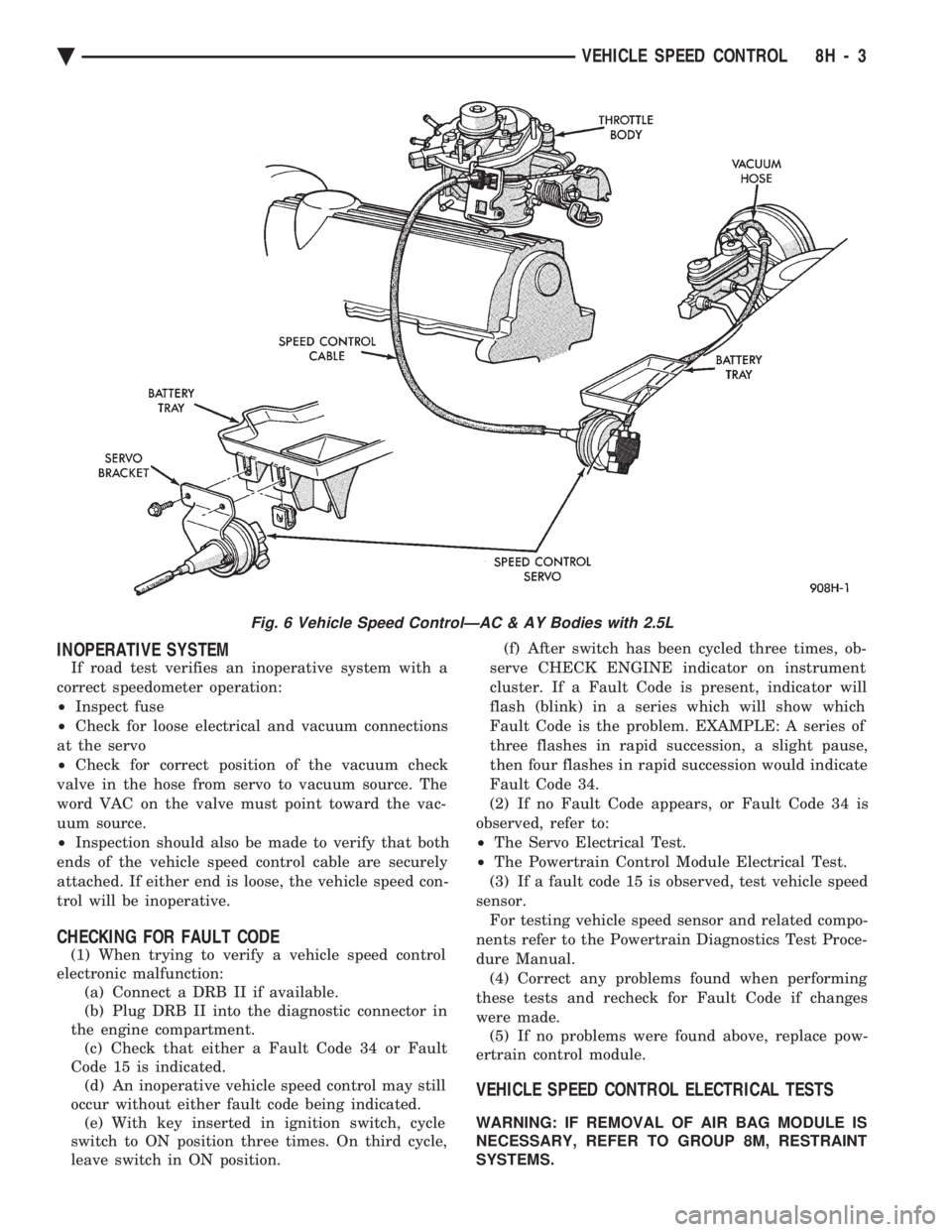
at the servo
² Check for correct position of the vacuum check
valve in the hose from servo to vacuum source. The
word VAC on the valve must point toward the vac-
uum source.
² Inspection should also be made to verify that both
ends of the vehicle speed control cable are securely
attached. If either end is loose, the vehicle speed con-
trol will be inoperative.
CHECKING FOR FAULT CODE
(1) When trying to verify a vehicle speed control
electronic malfunction: (a) Connect a DRB II if available.
(b) Plug DRB II into the diagnostic connector in
the engine compartment. (c) Check that either a Fault Code 34 or Fault
Code 15 is indicated. (d) An inoperative vehicle speed control may still
occur without either fault code being indicated. (e) With key inserted in ignition switch, cycle
switch to ON position three times. On third cycle,
leave switch in ON position. (f) After switch has been cycled three times, ob-
serve CHECK ENGINE indicator on instrument
cluster. If a Fault Code is present, indicator will
flash (blink) in a series which will show which
Fault Code is the problem. EXAMPLE: A series of
three flashes in rapid succession, a slight pause,
then four flashes in rapid succession would indicate
Fault Code 34.
(2) If no Fault Code appears, or Fault Code 34 is
observed, refer to:
² The Servo Electrical Test.
² The Powertrain Control Module Electrical Test.
(3) If a fault code 15 is observed, test vehicle speed
sensor. For testing vehicle speed sensor and related compo-
nents refer to the Powertrain Diagnostics Test Proce-
dure Manual. (4) Correct any problems found when performing
these tests and recheck for Fault Code if changes
were made. (5) If no problems were found above, replace pow-
ertrain control module.
VEHICLE SPEED CONTROL ELECTRICAL TESTS
WARNING: IF REMOVAL OF AIR BAG MODULE IS
NECESSARY, REFER TO GROUP 8M, RESTRAINT
SYSTEMS.
Fig. 6 Vehicle Speed ControlÐAC & AY Bodies with 2.5L
Ä VEHICLE SPEED CONTROL 8H - 3
Page 623 of 2438
(3) Secure arm to pivot with attaching nut and
tighten 17 to 22 N Im (155 to 195 in. lbs.) torque.
(4) Close head cover and remove pin from arm pin
hole.
WIPER ARM ADJUSTMENT
FRONT ARM ADJUSTMENT
(1) Cycle the wiper motor into the PARK position.
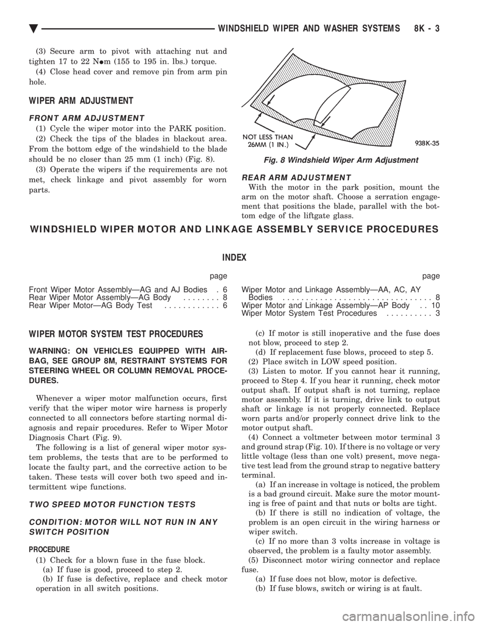
(2) Check the tips of the blades in blackout area.
From the bottom edge of the windshield to the blade
should be no closer than 25 mm (1 inch) (Fig. 8). (3) Operate the wipers if the requirements are not
met, check linkage and pivot assembly for worn
parts.
REAR ARM ADJUSTMENT
With the motor in the park position, mount the
arm on the motor shaft. Choose a serration engage-
ment that positions the blade, parallel with the bot-
tom edge of the liftgate glass.
WINDSHIELD WIPER MOTOR AND LINKAGE ASSEMBLY SERVICE PROCEDURES
INDEX
page page
Front Wiper Motor AssemblyÐAG and AJ Bodies . 6
Rear Wiper Motor AssemblyÐAG Body ........ 8
Rear Wiper MotorÐAG Body Test ............ 6 Wiper Motor and Linkage AssemblyÐAA, AC, AY
Bodies ................................ 8
Wiper Motor and Linkage AssemblyÐAP Body . . 10
Wiper Motor System Test Procedures .......... 3
WIPER MOTOR SYSTEM TEST PROCEDURES
WARNING: ON VEHICLES EQUIPPED WITH AIR-
BAG, SEE GROUP 8M, RESTRAINT SYSTEMS FOR
STEERING WHEEL OR COLUMN REMOVAL PROCE-
DURES.
Whenever a wiper motor malfunction occurs, first
verify that the wiper motor wire harness is properly
connected to all connectors before starting normal di-
agnosis and repair procedures. Refer to Wiper Motor
Diagnosis Chart (Fig. 9). The following is a list of general wiper motor sys-
tem problems, the tests that are to be performed to
locate the faulty part, and the corrective action to be
taken. These tests will cover both two speed and in-
termittent wipe functions.
TWO SPEED MOTOR FUNCTION TESTS
CONDITION: MOTOR WILL NOT RUN IN ANY SWITCH POSITION
PROCEDURE
(1) Check for a blown fuse in the fuse block. (a) If fuse is good, proceed to step 2.
(b) If fuse is defective, replace and check motor
operation in all switch positions. (c) If motor is still inoperative and the fuse does
not blow, proceed to step 2. (d) If replacement fuse blows, proceed to step 5.
(2) Place switch in LOW speed position.
(3) Listen to motor. If you cannot hear it running,
proceed to Step 4. If you hear it running, check motor
output shaft. If output shaft is not turning, replace
motor assembly. If it is turning, drive link to output
shaft or linkage is not properly connected. Replace
worn parts and/or properly connect drive link to the
motor output shaft. (4) Connect a voltmeter between motor terminal 3
and ground strap (Fig. 10). If there is no voltage or very
little voltage (less than one volt) present, move nega-
tive test lead from the ground strap to negative battery
terminal. (a) If an increase in voltage is noticed, the problem
is a bad ground circuit. Make sure the motor mount-
ing is free of paint and that nuts or bolts are tight. (b) If there is still no indication of voltage, the
problem is an open circuit in the wiring harness or
wiper switch. (c) If no more than 3 volts increase in voltage is
observed, the problem is a faulty motor assembly.
(5) Disconnect motor wiring connector and replace
fuse. (a) If fuse does not blow, motor is defective.
(b) If fuse blows, switch or wiring is at fault.
Fig. 8 Windshield Wiper Arm Adjustment
Ä WINDSHIELD WIPER AND WASHER SYSTEMS 8K - 3
Page 628 of 2438
(4) Remove the cowl top plastic screen.
(5) Remove pivot screws.
(6) Remove wiper motor cover and disconnect wiring
harness. (7) Remove three motor mounting nuts.
(8) Push pivots down into plenum chamber and pull
motor out until it clears the mounting studs. Then
move it as far to the drivers side or outboard as it will
go. Pull right pivot and link out through opening. Shift
motor to opposite side or inboard of opening and
remove motor, left link and pivot. (9) Clamp motor crank in a vise and remove nut
from end of motor shaft. Do not rotate motor output
shaft from PARK position.
INSTALLATION
(1) Assemble linkage to motor. Make sure crank fits
over D slot on motor shaft. Tighten mounting nut to 10
to 11 N Im (90 to 100 in. lbs.) torque. Be sure motor is
still in park position before assembling to linkage, if
not temporarily connect motor to wiring and operate
switch to position motor in park before assembling
linkage. (2) Place left pivot and link into plenum chamber.(a) Slide it all the way to the left or outboard side
until motor clears studs and crank is behind sheet
metal. (b) Push right pivot and link through opening.
(c) Move assembly right and position motor on
studs.
(3) Install three motor mounting nuts and tighten 7
to8N Im (60 70 in. lbs.) torque.
(4) Position pivots and install pivot screws and
tighten 7 to 8 N Im (60 to 70 in. lbs.) torque.
(5) Connect wiring to motor.
(6) Install motor cover. Tighten screws to 4 N Im (35
in. lbs.) torque. (7) Attach reservoir hose to T-connector through hole
provided in cowl screen. (8) Use plastic fasteners to install cowl screen.
(9) Install arm and blade assemblies. Refer to Wiper
Arm Adjustment. Connect arm washer hoses to
T-connector.
REAR WIPER MOTOR ASSEMBLYÐAG BODY
REMOVAL
(1) Remove arm and blade assembly, refer to Arm
and Blade Removal. (2) Unlock and open liftgate.
(3) Remove trim panel refer to Group 23, Body.
(4) Disconnect feed wire connector from motor.
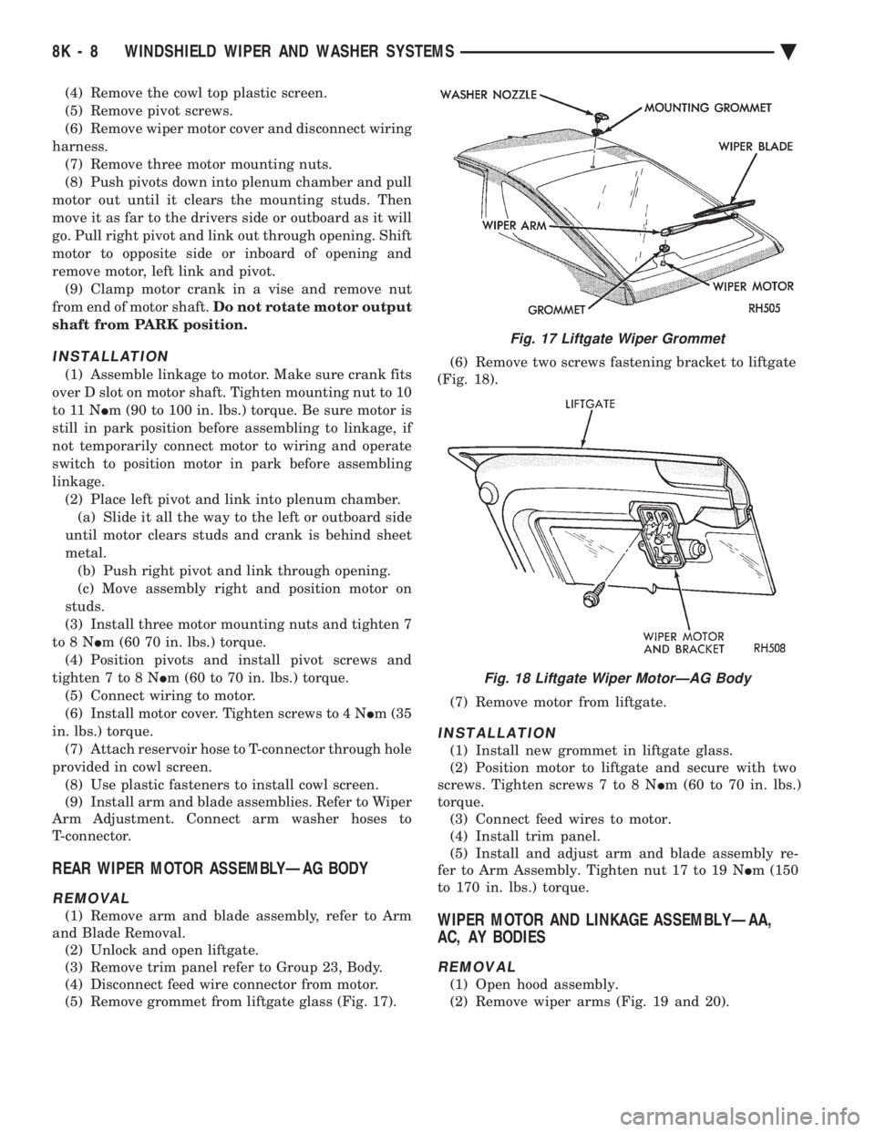
(5) Remove grommet from liftgate glass (Fig. 17). (6) Remove two screws fastening bracket to liftgate
(Fig. 18).
(7) Remove motor from liftgate.
INSTALLATION
(1) Install new grommet in liftgate glass.
(2) Position motor to liftgate and secure with two
screws. Tighten screws 7 to 8 N Im (60 to 70 in. lbs.)
torque. (3) Connect feed wires to motor.
(4) Install trim panel.
(5) Install and adjust arm and blade assembly re-
fer to Arm Assembly. Tighten nut 17 to 19 N Im (150
to 170 in. lbs.) torque.
WIPER MOTOR AND LINKAGE ASSEMBLYÐAA,
AC, AY BODIES
REMOVAL
(1) Open hood assembly.
(2) Remove wiper arms (Fig. 19 and 20).
Fig. 17 Liftgate Wiper Grommet
Fig. 18 Liftgate Wiper MotorÐAG Body
8K - 8 WINDSHIELD WIPER AND WASHER SYSTEMS Ä
Page 630 of 2438

(3) Remove cowl top plastic cover.
(4) Remove three attaching screws from each pivot.
(5) Disconnect the wiper motor wiring harness.
(6) Remove three bolts that attach motor mounting
bracket to body. (7) Remove wiper motor, bracket, and linkage as-
sembly from cowl plenum. (8) Clamp motor crank in a vise and remove nut
from end of motor shaft. Do not rotate motor out-
put shaft from PARK position.
INSTALLATION
(1) Assemble linkage to motor. Make sure crank
fits over D slot on motor shaft. Tighten mounting nut
10 to 11 N Im (90 to 100 in. lbs.) torque. Be sure mo-
tor is still in park position before assembling to link-
age, if not temporarily connect motor to wiring and
operate switch to position motor in park before as-
sembling linkage. (2) Install wiper motor, bracket, crank and linkage
assembly into cowl plenum. (3) Loosely install pivots and hose connector with
three attaching screws. (4) Secure motor mounting bracket screws to body
and tighten to 7 to 8 N Im (60 to 70 in. lbs.) torque.
(5) Tighten pivot attaching screws to 7 to 8 N Im
(60 to 70 in. lbs.) torque. (6) Attach wiper motor wiring harness. (7) Cycle wiper motor and turn OFF. To ensure
wiper motor is in the park position. (8) Install cowl top plastic cover.
(9) Install and adjust wiper arm assembly tighten
to 17 to 19 N Im (150 to 170 in. lbs.) torque.
WIPER MOTOR AND LINKAGE ASSEMBLYÐAP
BODY
REMOVAL
(1) Open hood assembly.
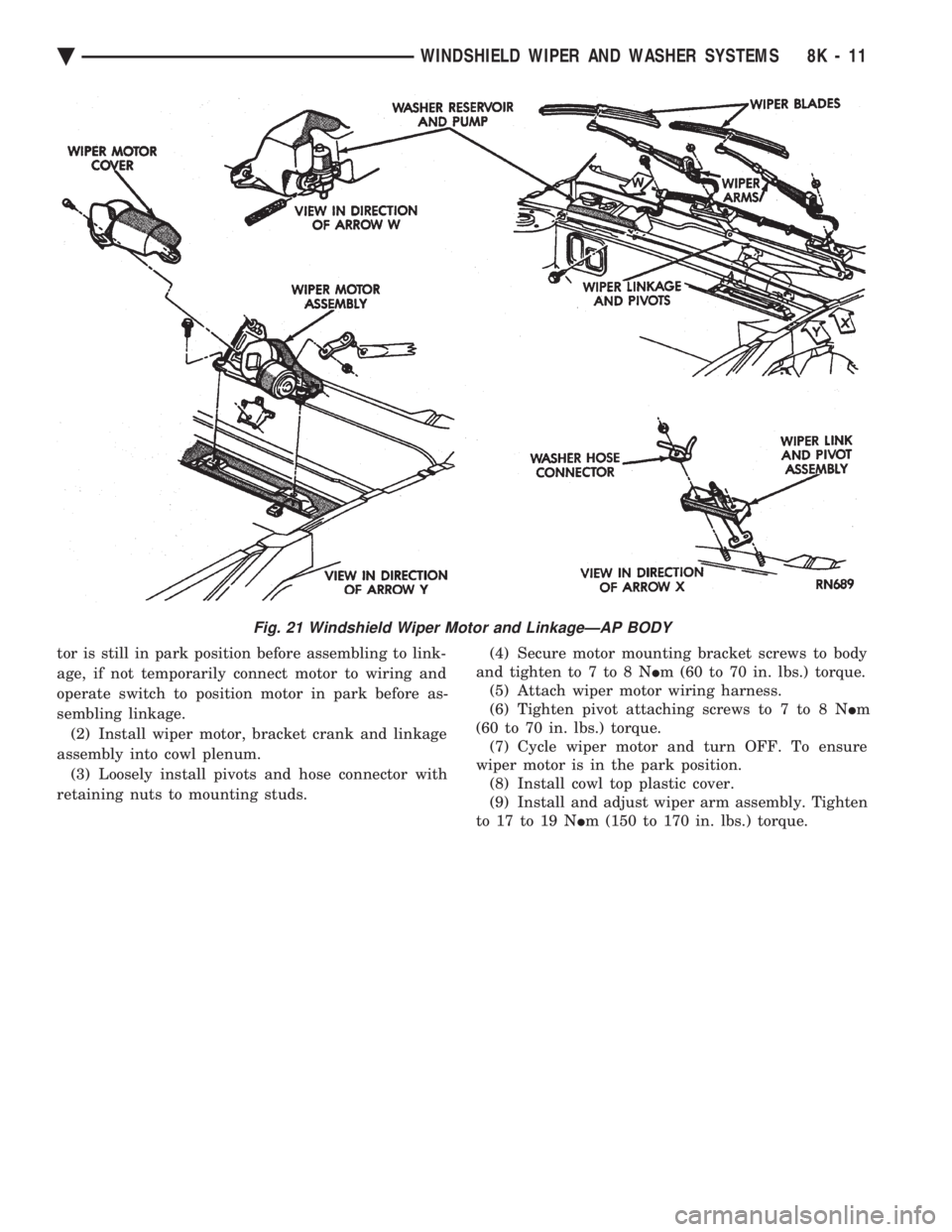
(2) Remove wiper arms (Fig. 21).
(3) Remove cowl top plastic cover.
(4) Disconnect the wiper motor wiring harness.
(5) Remove retaining nuts from the pivot mount-
ing studs. (6) Remove the three bolts that attach motor
mounting bracket to body. (7) Remove wiper motor, bracket, and linkage as-
sembly from cowl plenum. (8) Clamp motor crank in a vise and remove nut
from end of motor shaft. Do not rotate motor out-
put shaft from PARK position.
INSTALLATION
(1) Assemble linkage to motor. Make sure crank
fits over D slot on motor shaft. Tighten mounting nut
10 to 11 N Im (90 to 100 in. lbs.) torque. Be sure mo-
Fig. 20 Windshield Wiper Motor and LinkageÐAA Body
8K - 10 WINDSHIELD WIPER AND WASHER SYSTEMS Ä
Page 631 of 2438
tor is still in park position before assembling to link-
age, if not temporarily connect motor to wiring and
operate switch to position motor in park before as-
sembling linkage. (2) Install wiper motor, bracket crank and linkage
assembly into cowl plenum. (3) Loosely install pivots and hose connector with
retaining nuts to mounting studs. (4) Secure motor mounting bracket screws to body
and tighten to 7 to 8 N Im (60 to 70 in. lbs.) torque.
(5) Attach wiper motor wiring harness.
(6) Tighten pivot attaching screws to 7 to 8 N Im
(60 to 70 in. lbs.) torque. (7) Cycle wiper motor and turn OFF. To ensure
wiper motor is in the park position. (8) Install cowl top plastic cover.
(9) Install and adjust wiper arm assembly. Tighten
to 17 to 19 N Im (150 to 170 in. lbs.) torque.
Fig. 21 Windshield Wiper Motor and LinkageÐAP BODY
Ä WINDSHIELD WIPER AND WASHER SYSTEMS 8K - 11