1993 CHEVROLET PLYMOUTH ACCLAIM ECU
[x] Cancel search: ECUPage 1287 of 2438
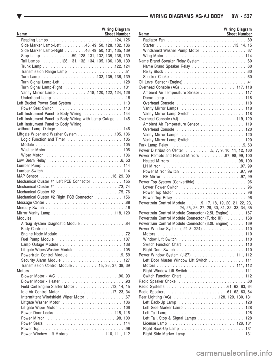
Wiring Diagram
Name Sheet Number
Reading Lamps ....................... .124, 126
Side Marker Lamp-Left .........45, 49, 50, 128, 132, 136
Side Marker Lamp-Right ........46, 49, 50, 131, 135, 139
Stop Lamp .......... .59, 128, 131, 132, 135, 136, 139
Tail Lamps .......128, 131, 132, 134, 135, 136, 138, 139
Trunk Lamp .......................... .122, 124
Transmission Range Lamp .....................51
Turn Lamp .................... .132, 135, 136, 139
Turn Signal Lamp-Left ...................... .128
Turn Signal Lamp-Right ..................... .131
Vanity Mirror Lamp ............118, 120, 122, 124, 126
Underhood Lamp ...........................16
Left Bucket Power Seat System ...................113
Power Seat Switch ........................ .113
Left Instrument Panel to Body Wiring ...............144
Left Instrument Panel to Body Wiring with Lamp Outage . . .145
Left Instrument Panel to Body Wiring without Lamp Outage ........................ .146
Liftgate Wiper and Washer System ..............105, 106
Logic Function and Timer .................... .105
Module ................................ .105
Washer Motor ........................... .106
Wiper Motor ............................ .106
Low Beam Relay ...........................6,53
Lumbar Pump ............................. .114
Lumbar Switch ............................ .114
MAP Sensor .......................... .18, 29, 30
Mechanical Cluster #1 Left PCB Connector ............155
Mechanical Cluster #1 ...................... .73, 74
Mechanical Cluster #2 ...................... .75, 76
Mechanical Cluster #2 Right PCB Connector ...........156
Message Center ..............................88
Mercury Switch ..............................16
Mirror Vanity Lamp ...................... .118, 120
Modules Airbag System Diagnostic Module .................84
Body Controller
Engine Node Module .........................72
Fuel Pump Module ........................ .107
Lamp Outage Module ....................... .138
Liftgate Wiper/Washer Module ..................105
Powertrain Control Module ...................9,59
Security Alarm Module ...................... .127
Transmission Control Module ..........15, 36, 37, 38, 39
Motors Blower Motor - A/C ...................... .90, 93
Blower Motor - Heater ........................93
Field Coil Engine Starter Motor ..............13, 14, 15
Idle Air Control Motor .................. .17, 23, 34
Intermittent Windshield Wiper Motor ...............67
Liftgate Washer Motor ...................... .106
Liftgate Wiper Motor ....................... .106
Power Door Locks ..................... .115, 116
Power Mirror ......................... .98, 100
Power Seats ............................ .114
Power Top ...............................96
Power Window Lift Motors ..............110, 111, 112Wiring Diagram
Name Sheet Number
Radiator Fan ..............................89
Starter ............................ .13, 14, 15
Windshield Washer Pump Motor .................67
Wing Motor ............................. .114
Name Brand Speaker Relay System .................60
Name Brand Speaker Relay .....................60
Relay Block ...............................60
Speaker Choke .............................60
Oil Level Sensor (Engine) ........................41
Overhead Console (AG) .................... .117, 118
Ambient Air Temperature Sensor .................117
Dome Lamp ............................. .118
Overhead Console ......................... .118
Vanity Mirror Lamps ....................... .118
Vanity Mirror Lamp Switch ................... .118
Overhead Console (AJ) .................... .119, 120
Ambient Air Temperature Sensor .................119
Overhead Console ......................... .120
Vanity Mirror Lamps ....................... .120
Vanity Mirror Lamp Switch ................... .120
Park Lamp Relay ...........................5,53
Power Distribution Center ..........5,7,9,10,11,12,160
Power Remote and Heated Mirrors .........97, 98, 99, 100
Heated Mirrors ........................ .98, 100
LH Mirror ............................ .97, 99
Power Mirror Switch ..................... .97, 99
RH Mirror ............................ .97, 99
Power Top System (Convertible) ...................96
Lower Power Switch .........................96
Power Top Motor ...........................96
Power Top Relay ...........................96
Powertrain Control Module ......9,17,18,19,20,21,22,23,
24, 25, 26, 27, 29, 30, 31, 32, 33, 34, 35
Powertrain Control Module Connector (2.5L Engine) ......167
Powertrain Control Module Connector (Turbo III) ........168
Powertrain Control Module Connector (3.0L Engine) ......169
Power Window System (J21 & G24) ................110
Motors ................................ .110
Window Lift Switch ........................ .110
Switch Function Chart ...................... .110
Right Door Switch ......................... .110
Power Window System (J-27) ................111, 112
Left Door Master Window Lift Switch ..............111
Motors ............................. .111, 112
Right Window Lift Switch .................... .111
Switch Function Chart ...................... .112
Radio Speaker Choke ..........................60
Radio Systems ...................... .61, 62, 63, 64
Radio Speakers ..................... .61, 62, 63, 64
Rear Lighting (AG) ................ .128, 129, 130, 131
Left Back-Up Lamp ........................ .128
Left Side Marker Lamp ...................... .128
Left Tail Lamp ........................... .128
Left Tail, Stop & Signal Lamps ..................128
License Lamp ........................ .128, 131
Right Back-Up Lamp ....................... .131
Right Side Marker Lamp ..................... .131
Ä WIRING DIAGRAMS AG-AJ BODY 8W - 537
Page 1288 of 2438
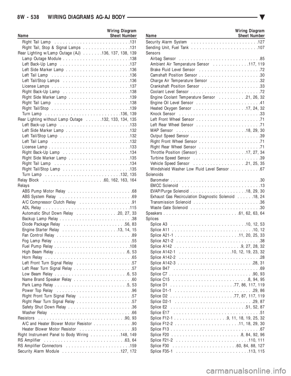
Wiring Diagram
Name Sheet Number
Right Tail Lamp .......................... .131
Right Tail, Stop & Signal Lamps .................131
Rear Lighting w/Lamp Outage (AJ) .......136, 137, 138, 139
Lamp Outage Module ....................... .138
Left Back-Up Lamp ........................ .137
Left Side Marker Lamp ...................... .136
Left Tail Lamp ........................... .136
Left Tail/Stop Lamps ....................... .136
License Lamps ........................... .137
Right Back-Up Lamp ....................... .138
Right Side Marker Lamp ..................... .139
Right Tail Lamp .......................... .138
Right Tail/Stop ........................... .139
Turn Lamp .......................... .136, 139
Rear Lighting without Lamp Outage ......132, 133, 134, 135
Left Back-up Lamp ........................ .133
Left Side Marker Lamp ...................... .132
Left Tail/Stop Lamp ........................ .132
Left Tail Lamp ........................... .132
License Lamp ............................ .133
Right Back-Up Lamp ....................... .134
Right Side Marker Lamp ..................... .135
Right Tail Lamp .......................... .134
Right Tail/Stop Lamp ....................... .135
Turn Lamp .......................... .132, 135
Relay Block ..................... .60, 162, 163, 164
Relays ABS Pump Motor Relay .......................68
ABS System Relay ..........................69
A/C Compressor Clutch Relay ...................91
ADL Relay .............................. .115
Automatic Shut Down Relay ...............20, 27, 33
Backup Lamp Relay ..........................38
Diode Package Relay ..................... .56, 83
Engine Starter Relay ................... .13, 14, 15
Fan Control Relay ...........................89
Fog Lamp Relay ............................55
Fuel Pump Relay .......................... .108
High Beam Relay ..........................6,53
Horn Relay ...............................65
Left Front Turn Signal Relay ....................57
Left Rear Turn Signal Relay .....................57
Low Beam Relay ..........................6,53
Name Brand Speaker Relay .....................60
Park Lamp Relay ..........................5,53
Power Top Relay ...........................96
Right Front Turn Signal Relay ...................57
Right Rear Turn Signal Relay ....................57
Safety Shut Down Relay .......................36
Washer Relay .............................66
Resistors .............................. .90, 93
A/C and Heater Blower Motor Resistor ..............90
Heater Blower Motor Resistor ...................93
Right Instrument Panel to Body Wiring ...........148, 149
RS Amplifier ............................ .63, 64
RS Amplifier Connectors ...................... .159
Security Alarm Module .................... .127, 172Wiring Diagram
Name Sheet Number
Security Alarm System ....................... .127
Sending Unit, Fuel Tank ....................... .107
Sensors Airbag Sensor .............................85
Ambient Air Temperature Sensor .............117, 119
Brake Fluid Level Sensor ......................72
Camshaft Position Sensor ......................30
Charge Air Temperature Sensor ..................32
Crankshaft Position Sensor .....................33
Coolant Level Sensor .........................72
Engine Coolant Temperature Sensor ..........21, 26, 32
Engine Oil Level Sensor .......................41
Heated Oxygen Sensor .................. .17, 24, 32
Knock Sensor .............................33
Left Front Wheel Sensor .......................71
Left Rear Wheel Sensor .......................71
MAP Sensor ........................ .18, 29, 30
Output Speed Sensor .........................39
Right Front Wheel Sensor ......................71
Right Rear Wheel Sensor ......................71
Throttle Position (Sensor) .................17, 27, 34
Turbine Speed Sensor ........................39
Vehicle Speed Sensor .................. .21, 25, 35
Windshield Washer Low Fluid Level Sensor ...........67
Solenoids Barometer ................................30
EMCC Solenoid ............................13
EVAP/Purge Solenoid ................... .18, 29, 30
Exhaust Gas Recirculation Diagnostic Solenoid ......18, 24
Transmission Solenoid ........................36
Waste Gate Solenoid .........................30
Speakers .......................... .61, 62, 63, 64
Splices Splice A3 .......................... .10, 12, 53
Splice A11 ............................ .10, 12
Splice A21-1 ...................... .11, 20, 25, 33
Splice A21-2 ..............................38
Splice A142 ........................9,27,28,32
Splice A142-1 .................. .10, 12, 19, 23, 32
Splice A142-2 .............................28
Splice A142-3 .......................... .28, 31
Splice B47 ...............................69
Splice C7 ............................. .90, 93
Splice C15 ...........................8,94,95
Splice D1 ...................... .77, 86, 117, 119
Splice D1-1 ........................... .29, 86
Splice D2 ...................... .77, 87, 117, 119
Splice D2-1 ........................... .29, 87
Splice E2 .......................... .51, 52, 87
Splice E17 ...............................51
Splice F12-1 ...................9,11,18,19,25,32
Splice F12-2 ...................... .11, 18, 29, 30
Splice F13 ................................67
Splice F20 .........................8,84,92,96
Splice F21-2 ......................... .110, 111
Splice F30 ...................... .60, 84, 88, 127
Splice F35-1 ......................... .113, 115
8W - 538 WIRING DIAGRAMS AG-AJ BODY Ä
Page 1567 of 2438
ENGINE
CONTENTS
page page
2.2/2.5L ENGINES ....................... 8
3.0L ENGINE .......................... 66 3.3/3.8L ENGINE
....................... 98
STANDARD SERVICE PROCEDURES ......... 1
STANDARD SERVICE PROCEDURES INDEX
page page
Crankshaft Sprocket Bolt Access Plug .......... 2
Engine Performance ....................... 2
Form-In-Place Gaskets ..................... 1
Honing Cylinder Bores ..................... 2
Hydrostatic Locked Engine .................. 5 Lash Adjuster (Tappet) Noise Diagnosis
........ 4
Measuring Main Bearing Clearance and Connecting Rod Bearing Clearance ................... 3
Repair of Damaged or Worn Threads .......... 4
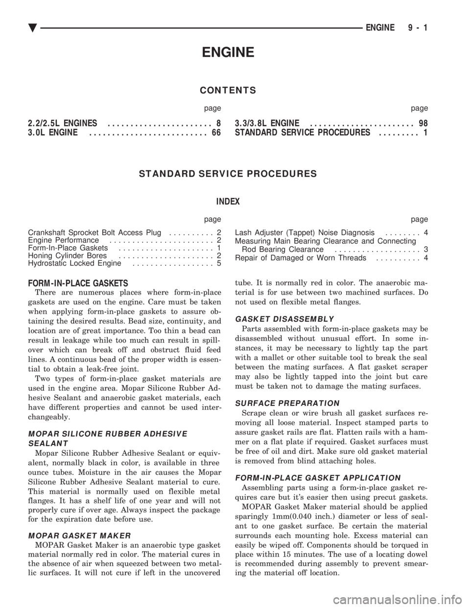
FORM-IN-PLACE GASKETS
There are numerous places where form-in-place
gaskets are used on the engine. Care must be taken
when applying form-in-place gaskets to assure ob-
taining the desired results. Bead size, continuity, and
location are of great importance. Too thin a bead can
result in leakage while too much can result in spill-
over which can break off and obstruct fluid feed
lines. A continuous bead of the proper width is essen-
tial to obtain a leak-free joint. Two types of form-in-place gasket materials are
used in the engine area. Mopar Silicone Rubber Ad-
hesive Sealant and anaerobic gasket materials, each
have different properties and cannot be used inter-
changeably.
MOPAR SILICONE RUBBER ADHESIVE SEALANT
Mopar Silicone Rubber Adhesive Sealant or equiv-
alent, normally black in color, is available in three
ounce tubes. Moisture in the air causes the Mopar
Silicone Rubber Adhesive Sealant material to cure.
This material is normally used on flexible metal
flanges. It has a shelf life of one year and will not
properly cure if over age. Always inspect the package
for the expiration date before use.
MOPAR GASKET MAKER
MOPAR Gasket Maker is an anaerobic type gasket
material normally red in color. The material cures in
the absence of air when squeezed between two metal-
lic surfaces. It will not cure if left in the uncovered tube. It is normally red in color. The anaerobic ma-
terial is for use between two machined surfaces. Do
not used on flexible metal flanges.
GASKET DISASSEMBLY
Parts assembled with form-in-place gaskets may be
disassembled without unusual effort. In some in-
stances, it may be necessary to lightly tap the part
with a mallet or other suitable tool to break the seal
between the mating surfaces. A flat gasket scraper
may also be lightly tapped into the joint but care
must be taken not to damage the mating surfaces.
SURFACE PREPARATION
Scrape clean or wire brush all gasket surfaces re-
moving all loose material. Inspect stamped parts to
assure gasket rails are flat. Flatten rails with a ham-
mer on a flat plate if required. Gasket surfaces must
be free of oil and dirt. Make sure old gasket material
is removed from blind attaching holes.
FORM-IN-PLACE GASKET APPLICATION
Assembling parts using a form-in-place gasket re-
quires care but it's easier then using precut gaskets. MOPAR Gasket Maker material should be applied
sparingly 1mm(0.040 inch.) diameter or less of seal-
ant to one gasket surface. Be certain the material
surrounds each mounting hole. Excess material can
easily be wiped off. Components should be torqued in
place within 15 minutes. The use of a locating dowel
is recommended during assembly to prevent smear-
ing the material off location.
Ä ENGINE 9 - 1
Page 1580 of 2438
CAUTION: Make sure clutch cable has been discon-
nected. (20) Remove front engine mount screw and nut.
(21) Remove manual transmission damper.
(22) Remove left insulator through bolt from inside
wheelhouse or insulator bracket to transmission
screws. (23) Remove engine from vehicle.
INSTALLATION
(1) Install hoist to the engine and lower engine
into the engine compartment. SEE: ENGINE MOUNT RUBBER INSULATORS,
THIS GROUP. (2) Align engine mounts and install but do not
tighten until all mounting bolts have been installed.
(3) Install transmission case to cylinder block
mounting screws. Tighten to 95 N Im (70 ft. lbs.)
torque. (4) Remove engine hoist and transmission holding
fixture. (5) Install ground strap.
(6) Install right inner splash shield.
(7) Connect starter. See Electrical Group 8 for in-
stallation. (8) Connect exhaust system. See Exhaust Systems
Group 11 for installation. (9) Manual Transmission: Install transmission
case lower cover. Automatic Transmission: Remove C clamp from
torque converter housing. Align flexplate to torque
converter and install mounting screws. Tighten to 75
N Im (55 ft. lbs.) torque.
(10) Manual Transmission: Connect clutch cable.
See Clutch Group 6. (11) Install power steering pump. Refer to Cooling
System Group 7, Accessory Drive Section for belt
tension adjustment. (12) Connect fuel line, heater hose, and accelerator
cable. (13) Connect all electrical connections and har-
nesses at throttle body and engine. (14) Install oil filter. Fill engine crankcase with
proper oil to correct level. (15) Install air conditioning compressor (if
equipped). See Heater and Air Conditioning, Group
24 for installation. (16) Install air cleaner and hoses.
(17) Install radiator and shroud assembly . Install
radiator hoses. Fill cooling system. See Cooling Sys-
tem Group 7 for filling procedure. (18) Install hood.
(19) Connect battery.
(20) Start engine and run until operating temper-
ature is reached. (21) Adjust transmission linkage, if necessary.
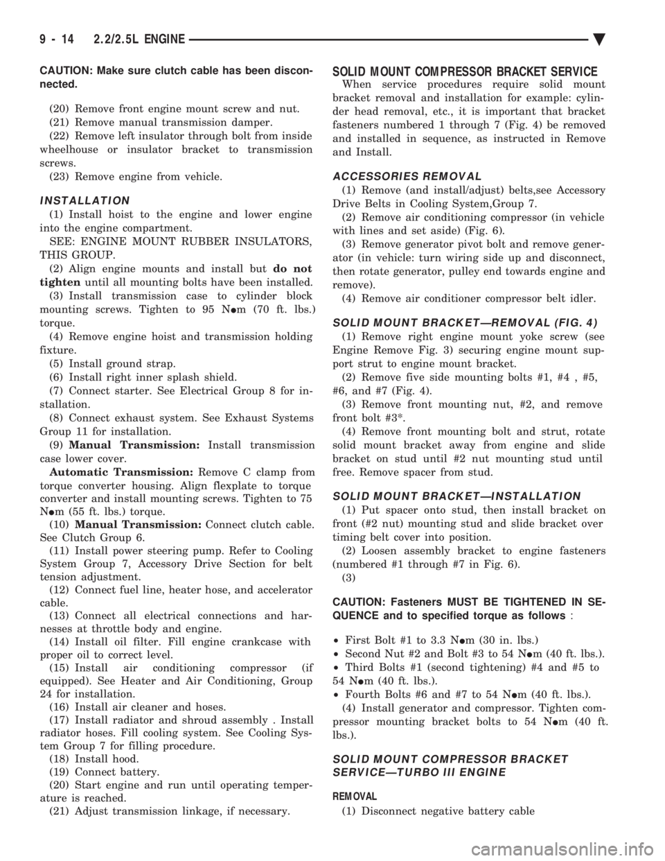
SOLID MOUNT COMPRESSOR BRACKET SERVICE
When service procedures require solid mount
bracket removal and installation for example: cylin-
der head removal, etc., it is important that bracket
fasteners numbered 1 through 7 (Fig. 4) be removed
and installed in sequence, as instructed in Remove
and Install.
ACCESSORIES REMOVAL
(1) Remove (and install/adjust) belts,see Accessory
Drive Belts in Cooling System,Group 7. (2) Remove air conditioning compressor (in vehicle
with lines and set aside) (Fig. 6). (3) Remove generator pivot bolt and remove gener-
ator (in vehicle: turn wiring side up and disconnect,
then rotate generator, pulley end towards engine and
remove). (4) Remove air conditioner compressor belt idler.
SOLID MOUNT BRACKETÐREMOVAL (FIG. 4)
(1) Remove right engine mount yoke screw (see
Engine Remove Fig. 3) securing engine mount sup-
port strut to engine mount bracket. (2) Remove five side mounting bolts #1, #4 , #5,
#6, and #7 (Fig. 4). (3) Remove front mounting nut, #2, and remove
front bolt #3*. (4) Remove front mounting bolt and strut, rotate
solid mount bracket away from engine and slide
bracket on stud until #2 nut mounting stud until
free. Remove spacer from stud.
SOLID MOUNT BRACKETÐINSTALLATION
(1) Put spacer onto stud, then install bracket on
front (#2 nut) mounting stud and slide bracket over
timing belt cover into position. (2) Loosen assembly bracket to engine fasteners
(numbered #1 through #7 in Fig. 6). (3)
CAUTION: Fasteners MUST BE TIGHTENED IN SE-
QUENCE and to specified torque as follows :
² First Bolt #1 to 3.3 N Im (30 in. lbs.)
² Second Nut #2 and Bolt #3 to 54 N Im (40 ft. lbs.).
² Third Bolts #1 (second tightening) #4 and #5 to
54 N Im (40 ft. lbs.).
² Fourth Bolts #6 and #7 to 54 N Im (40 ft. lbs.).
(4) Install generator and compressor. Tighten com-
pressor mounting bracket bolts to 54 N Im (40 ft.
lbs.).
SOLID MOUNT COMPRESSOR BRACKET SERVICEÐTURBO III ENGINE
REMOVAL
(1) Disconnect negative battery cable
9 - 14 2.2/2.5L ENGINE Ä
Page 1587 of 2438
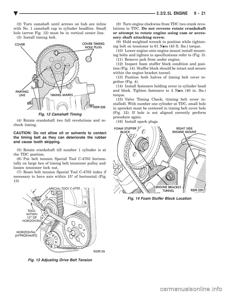
(2) Turn camshaft until arrows on hub are inline
with No. 1 camshaft cap to cylinder headline. Small
hole (arrow Fig. 12) must be in vertical center line. (3) Install timing belt.
(4) Rotate crankshaft two full revolutions and re-
check timing.
CAUTION: Do not allow oil or solvents to contact
the timing belt as they can deteriorate the rubber
and cause tooth skipping.
(5) Rotate crankshaft till number 1 cylinder is at
the TDC position. (6) Put belt tension Special Tool C-4703 horizon-
tally on large hex of timing belt tensioner pulley and
loosen tensioner lock nut. (7) Reset belt tension Special Tool C-4703 index if
necessary to have axis within 15É of horizontal. (Fig.
13) (8) Turn engine clockwise from TDC two crank revo-
lutions to TDC. Do not reverse rotate crankshaft
or attempt to rotate engine using cam or acces-
sory shaft attaching screw. (9) Hold weighted wrench in position while tighten-
ing bolt on tensioner to 61 N Im (45 ft. lbs.) torque.
(10) Lower engine onto engine mount install mount-
ing bolts and tighten to specifications refer to (Fig. 3). (11) Remove jack from under engine.
(12) Inspect foam stuffer block condition and posi-
tion (Fig. 14). Stuffer block should be intact and secure
within the engine bracket tunnel. (13) Position both halves of timing belt cover to-
gether (Fig. 4). (14) Install fasteners holding cover to cylinder head
and block. Tighten fasteners to 4 N Im (40 in. lbs.)
torque. (15) Valve Timing Check; (timing belt cover in-
stalled). With number one cylinder at TDC, small hole
in sprocket must be centered in timing belt cover hole
(Fig. 12). If hole is not aligned correctly perform
procedure again. (16) Install spark plugs.
Fig. 12 Camshaft Timing
Fig. 13 Adjusting Drive Belt Tension
Fig. 14 Foam Stuffer Block Location
Ä 2.2/2.5L ENGINE 9 - 21
Page 1601 of 2438
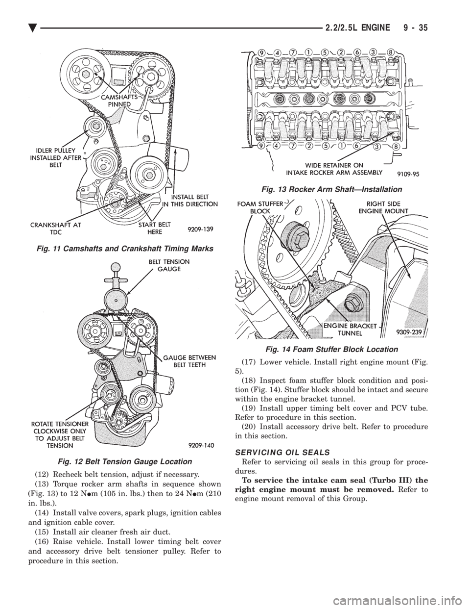
(12) Recheck belt tension, adjust if necessary.
(13) Torque rocker arm shafts in sequence shown
(Fig. 13) to 12 N Im (105 in. lbs.) then to 24 N Im (210
in. lbs.). (14) Install valve covers, spark plugs, ignition cables
and ignition cable cover. (15) Install air cleaner fresh air duct.
(16) Raise vehicle. Install lower timing belt cover
and accessory drive belt tensioner pulley. Refer to
procedure in this section. (17) Lower vehicle. Install right engine mount (Fig.
5). (18) Inspect foam stuffer block condition and posi-
tion (Fig. 14). Stuffer block should be intact and secure
within the engine bracket tunnel. (19) Install upper timing belt cover and PCV tube.
Refer to procedure in this section. (20) Install accessory drive belt. Refer to procedure
in this section.
SERVICING OIL SEALS
Refer to servicing oil seals in this group for proce-
dures. To service the intake cam seal (Turbo III) the
right engine mount must be removed. Refer to
engine mount removal of this Group.
Fig. 13 Rocker Arm ShaftÐInstallation
Fig. 14 Foam Stuffer Block Location
Fig. 11 Camshafts and Crankshaft Timing Marks
Fig. 12 Belt Tension Gauge Location
Ä 2.2/2.5L ENGINE 9 - 35
Page 1674 of 2438
(15) Install rocker arm covers tighten screws to 14
N Im (120 in. lbs.) and connector to ignition coils.
(16) Install Intake Manifold; Refer to Intake Mani-
fold Installation 3.3/3.8L Engine, Group 11 Exhaust
System and Intake Manifold.
HYDRAULIC TAPPETS
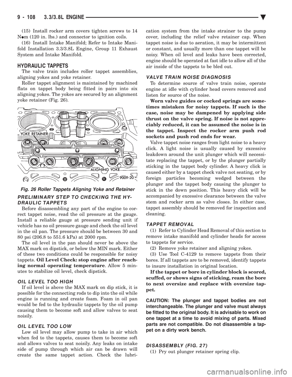
The valve train includes roller tappet assemblies,
aligning yokes and yoke retainer. Roller tappet alignment is maintained by machined
flats on tappet body being fitted in pairs into six
aligning yokes. The yokes are secured by an alignment
yoke retainer (Fig. 26).
PRELIMINARY STEP TO CHECKING THE HY- DRAULIC TAPPETS
Before disassembling any part of the engine to cor-
rect tappet noise, read the oil pressure at the gauge.
Install a reliable gauge at pressure sending unit if
vehicle has no oil pressure gauge and check the oil level
in the oil pan. The pressure should be between 30 and
80 psi (206.8 to 551.6 kPa) at 2000 rpm. The oil level in the pan should never be above the
MAX mark on dipstick, or below the MIN mark. Either
of these two conditions could be responsible for noisy
tappets. Oil Level Check: stop engine after reach-
ing normal operating temperature . Allow 5 min-
utes to stabilize oil level, check dipstick.
OIL LEVEL TOO HIGH
If oil level is above the MAX mark on dip stick, it is
possible for the connecting rods to dip into the oil while
engine is running and create foam. Foam in oil pan
would be fed to the hydraulic tappets by the oil pump
causing them to become soft and allow valves to seat
noisily.
OIL LEVEL TOO LOW
Low oil level may allow pump to take in air which
when fed to the tappets, causes them to become soft
and allows valves to seat noisily. Any leaks on intake
side of pump through which air can be drawn will
create the same tappet action. Check the lubri- cation system from the intake strainer to the pump
cover, including the relief valve retainer cap. When
tappet noise is due to aeration, it may be intermittent
or constant, and usually more than one tappet will be
noisy. When oil level and leaks have been corrected,
engine should be operated at fast idle to allow all of the
air inside of the tappets to be bled out.
VALVE TRAIN NOISE DIAGNOSIS
To determine source of valve train noise, operate
engine at idle with cylinder head covers removed and
listen for source of the noise. Worn valve guides or cocked springs are some-
times mistaken for noisy tappets. If such is the
case, noise may be dampened by applying side
thrust on the valve spring. If noise is not appre-
ciably reduced, it can be assumed the noise is in
the tappet. Inspect the rocker arm push rod
sockets and push rod ends for wear. Valve tappet noise ranges from light noise to a heavy
click. A light noise is usually caused by excessive
leakdown around the unit plunger which will necessi-
tate replacing the tappet, or by the plunger partially
sticking in the tappet body cylinder. A heavy click is
caused either by a tappet check valve not seating, or by
foreign particles becoming wedged between the
plunger and the tappet body causing the plunger to
stick in the down position. This heavy click will be
accompanied by excessive clearance between the valve
stem and rocker arm as valve closes. In either case,
tappet assembly should be removed for inspection and
cleaning.
TAPPET REMOVAL
(1) Refer to Cylinder Head Removal of this section to
remove intake manifold and cylinder heads for access
to tappets for service. (2) Remove yoke retainer and aligning yokes.
(3) Use Tool C-4129 to remove tappets from their
bores. If all tappets are to be removed, identify tappets
to insure installation in original location. If the tappet or bore in cylinder block is scored,
scuffed, or shows signs of sticking, ream the bore
to next oversize and replace with oversize tap-
pet.
CAUTION: The plunger and tappet bodies are not
interchangeable. The plunger and valve must always
be fitted to the original body. It is advisable to work on
one tappet at a time to avoid mixing of parts. Mixed
parts are not compatible. Do not disassemble a tap-
pet on a dirty work bench.
DISASSEMBLY (FIG. 27)
(1) Pry out plunger retainer spring clip.
Fig. 26 Roller Tappets Aligning Yoke and Retainer
9 - 108 3.3/3.8L ENGINE Ä
Page 1776 of 2438
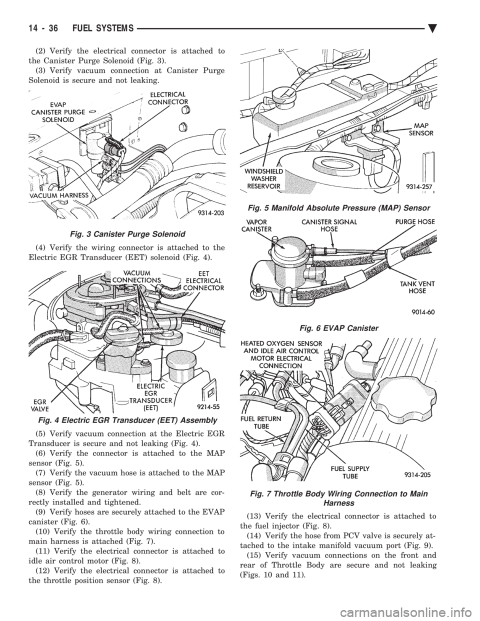
(2) Verify the electrical connector is attached to
the Canister Purge Solenoid (Fig. 3). (3) Verify vacuum connection at Canister Purge
Solenoid is secure and not leaking.
(4) Verify the wiring connector is attached to the
Electric EGR Transducer (EET) solenoid (Fig. 4).
(5) Verify vacuum connection at the Electric EGR
Transducer is secure and not leaking (Fig. 4). (6) Verify the connector is attached to the MAP
sensor (Fig. 5). (7) Verify the vacuum hose is attached to the MAP
sensor (Fig. 5). (8) Verify the generator wiring and belt are cor-
rectly installed and tightened. (9) Verify hoses are securely attached to the EVAP
canister (Fig. 6). (10) Verify the throttle body wiring connection to
main harness is attached (Fig. 7). (11) Verify the electrical connector is attached to
idle air control motor (Fig. 8). (12) Verify the electrical connector is attached to
the throttle position sensor (Fig. 8). (13) Verify the electrical connector is attached to
the fuel injector (Fig. 8). (14) Verify the hose from PCV valve is securely at-
tached to the intake manifold vacuum port (Fig. 9). (15) Verify vacuum connections on the front and
rear of Throttle Body are secure and not leaking
(Figs. 10 and 11).
Fig. 3 Canister Purge Solenoid
Fig. 4 Electric EGR Transducer (EET) Assembly
Fig. 5 Manifold Absolute Pressure (MAP) Sensor
Fig. 6 EVAP Canister
Fig. 7 Throttle Body Wiring Connection to Main Harness
14 - 36 FUEL SYSTEMS Ä