1993 CHEVROLET PLYMOUTH ACCLAIM ECU
[x] Cancel search: ECUPage 1949 of 2438
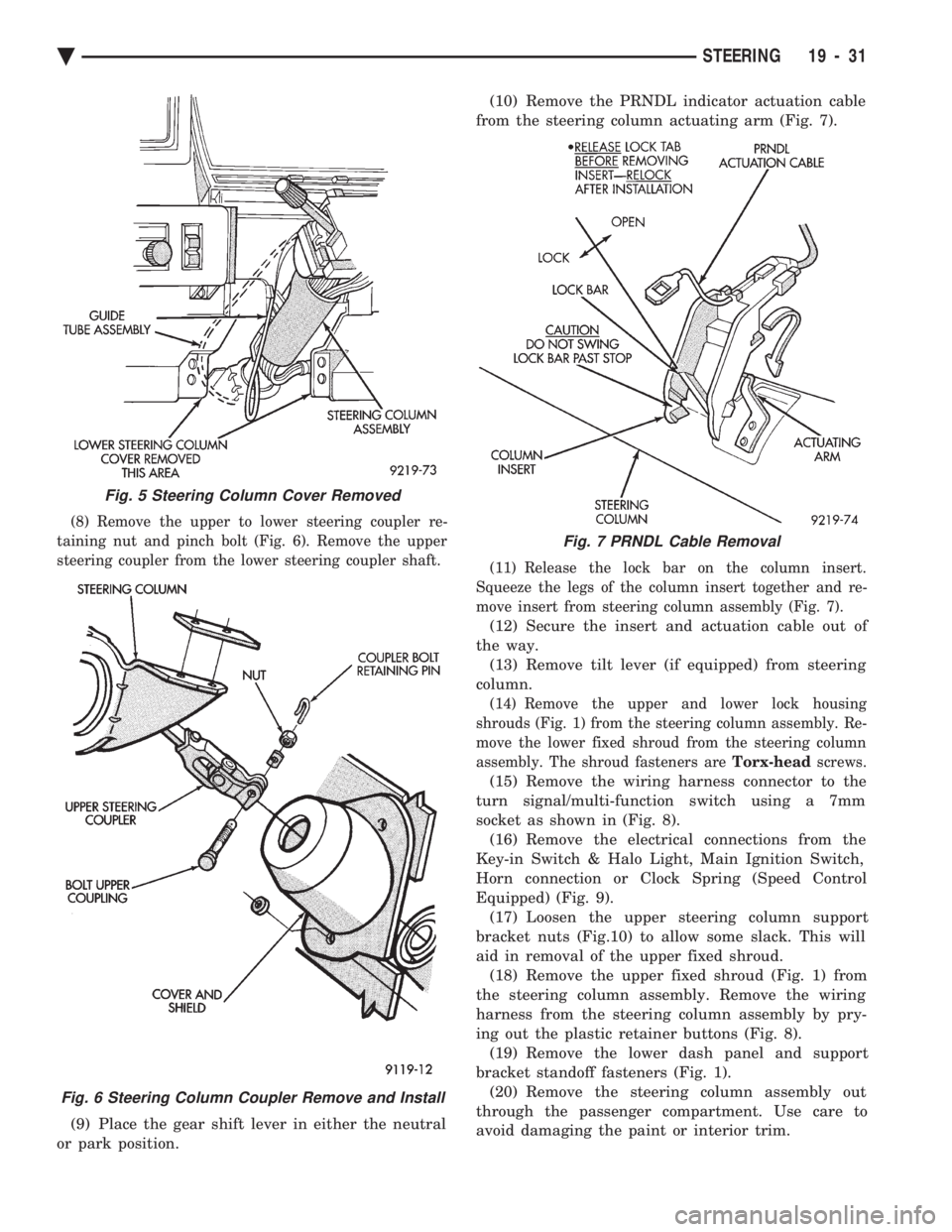
(8) Remove the upper to lower steering coupler re-
taining nut and pinch bolt (Fig. 6). Remove the upper
steering coupler from the lower steering coupler shaft.
(9) Place the gear shift lever in either the neutral
or park position. (10) Remove the PRNDL indicator actuation cable
from the steering column actuating arm (Fig. 7).
(11) Release the lock bar on the column insert.
Squeeze the legs of the column insert together and re-
move insert from steering column assembly (Fig. 7).
(12) Secure the insert and actuation cable out of
the way. (13) Remove tilt lever (if equipped) from steering
column.
(14) Remove the upper and lower lock housing
shrouds (Fig. 1) from the steering column assembly. Re-
move the lower fixed shroud from the steering column
assembly. The shroud fasteners are Torx-headscrews.
(15) Remove the wiring harness connector to the
turn signal/multi-function switch using a 7mm
socket as shown in (Fig. 8). (16) Remove the electrical connections from the
Key-in Switch & Halo Light, Main Ignition Switch,
Horn connection or Clock Spring (Speed Control
Equipped) (Fig. 9). (17) Loosen the upper steering column support
bracket nuts (Fig.10) to allow some slack. This will
aid in removal of the upper fixed shroud. (18) Remove the upper fixed shroud (Fig. 1) from
the steering column assembly. Remove the wiring
harness from the steering column assembly by pry-
ing out the plastic retainer buttons (Fig. 8). (19) Remove the lower dash panel and support
bracket standoff fasteners (Fig. 1). (20) Remove the steering column assembly out
through the passenger compartment. Use care to
avoid damaging the paint or interior trim.
Fig. 5 Steering Column Cover Removed
Fig. 6 Steering Column Coupler Remove and Install
Fig. 7 PRNDL Cable Removal
Ä STEERING 19 - 31
Page 1951 of 2438
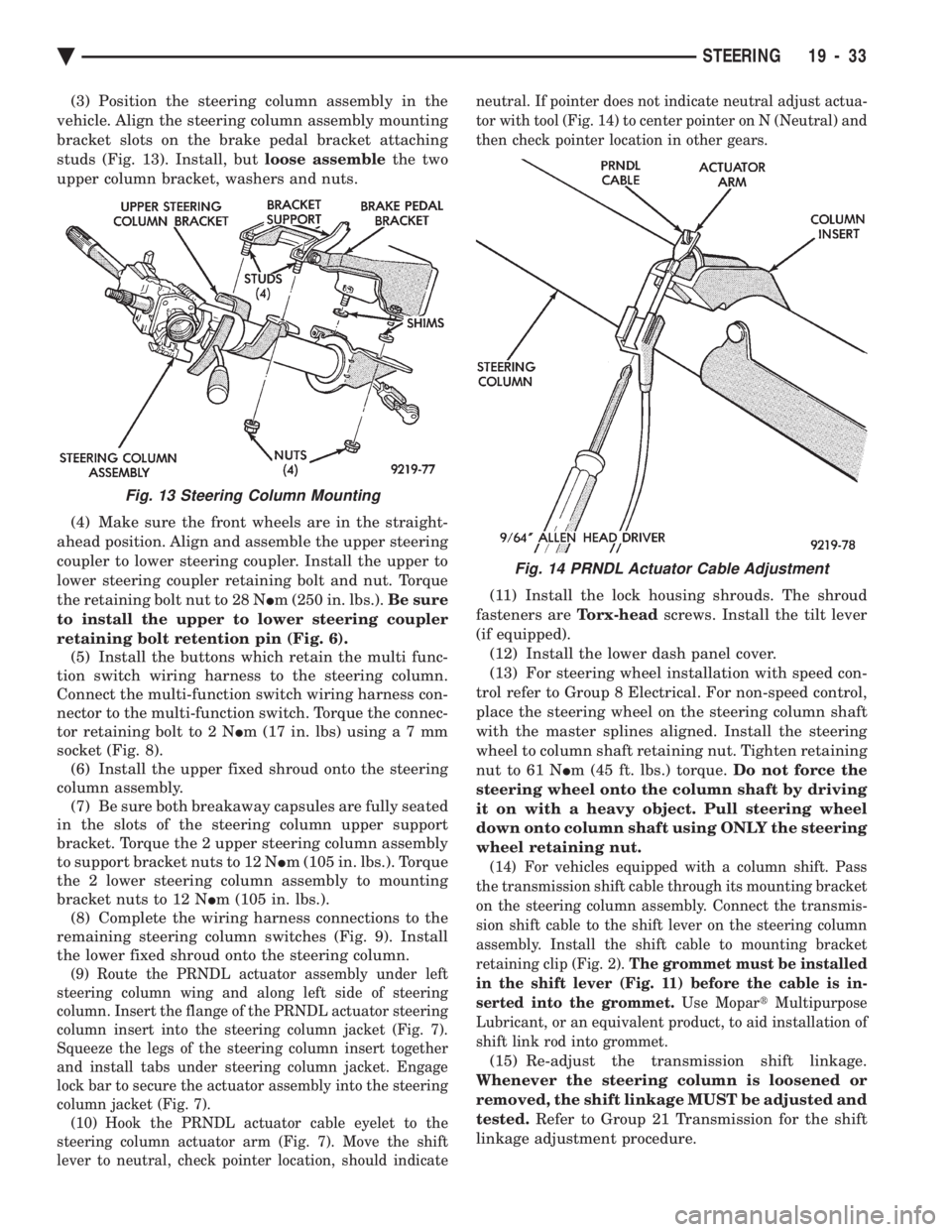
(3) Position the steering column assembly in the
vehicle. Align the steering column assembly mounting
bracket slots on the brake pedal bracket attaching
studs (Fig. 13). Install, but loose assemblethe two
upper column bracket, washers and nuts.
(4) Make sure the front wheels are in the straight-
ahead position. Align and assemble the upper steering
coupler to lower steering coupler. Install the upper to
lower steering coupler retaining bolt and nut. Torque
the retaining bolt nut to 28 N Im (250 in. lbs.). Be sure
to install the upper to lower steering coupler
retaining bolt retention pin (Fig. 6). (5) Install the buttons which retain the multi func-
tion switch wiring harness to the steering column.
Connect the multi-function switch wiring harness con-
nector to the multi-function switch. Torque the connec-
tor retaining bolt to 2 N Im (17 in. lbs) usin ga7mm
socket (Fig. 8). (6) Install the upper fixed shroud onto the steering
column assembly. (7) Be sure both breakaway capsules are fully seated
in the slots of the steering column upper support
bracket. Torque the 2 upper steering column assembly
to support bracket nuts to 12 N Im (105 in. lbs.). Torque
the 2 lower steering column assembly to mounting
bracket nuts to 12 N Im (105 in. lbs.).
(8) Complete the wiring harness connections to the
remaining steering column switches (Fig. 9). Install
the lower fixed shroud onto the steering column.
(9) Route the PRNDL actuator assembly under left
steering column wing and along left side of steering
column. Insert the flange of the PRNDL actuator steering
column insert into the steering column jacket (Fig. 7).
Squeeze the legs of the steering column insert together
and install tabs under steering column jacket. Engage
lock bar to secure the actuator assembly into the steering
column jacket (Fig. 7). (10) Hook the PRNDL actuator cable eyelet to the
steering column actuator arm (Fig. 7). Move the shift
lever to neutral, check pointer location, should indicate neutral. If pointer does not indicate neutral adjust actua-
tor with tool (Fig. 14) to center pointer on N (Neutral) and
then check pointer location in other gears.
(11) Install the lock housing shrouds. The shroud
fasteners are Torx-headscrews. Install the tilt lever
(if equipped). (12) Install the lower dash panel cover.
(13) For steering wheel installation with speed con-
trol refer to Group 8 Electrical. For non-speed control,
place the steering wheel on the steering column shaft
with the master splines aligned. Install the steering
wheel to column shaft retaining nut. Tighten retaining
nut to 61 N Im (45 ft. lbs.) torque. Do not force the
steering wheel onto the column shaft by driving
it on with a heavy object. Pull steering wheel
down onto column shaft using ONLY the steering
wheel retaining nut.
(14) For vehicles equipped with a column shift. Pass
the transmission shift cable through its mounting bracket
on the steering column assembly. Connect the transmis-
sion shift cable to the shift lever on the steering column
assembly. Install the shift cable to mounting bracket
retaining clip (Fig. 2). The grommet must be installed
in the shift lever (Fig. 11) before the cable is in-
serted into the grommet. Use MopartMultipurpose
Lubricant, or an equivalent product, to aid installation of
shift link rod into grommet.
(15) Re-adjust the transmission shift linkage.
Whenever the steering column is loosened or
removed, the shift linkage MUST be adjusted and
tested. Refer to Group 21 Transmission for the shift
linkage adjustment procedure.
Fig. 13 Steering Column Mounting
Fig. 14 PRNDL Actuator Cable Adjustment
Ä STEERING 19 - 33
Page 2005 of 2438
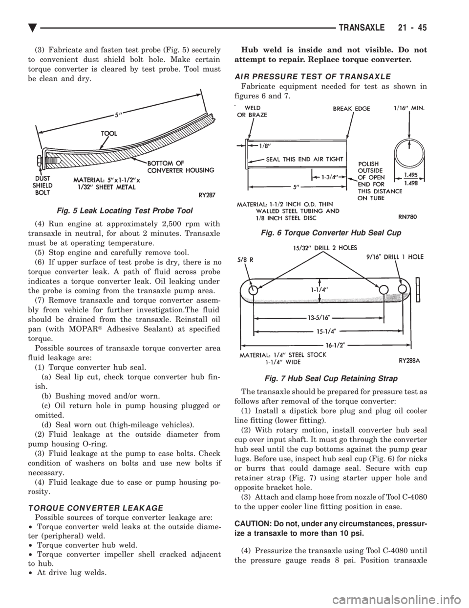
(3) Fabricate and fasten test probe (Fig. 5) securely
to convenient dust shield bolt hole. Make certain
torque converter is cleared by test probe. Tool must
be clean and dry.
(4) Run engine at approximately 2,500 rpm with
transaxle in neutral, for about 2 minutes. Transaxle
must be at operating temperature. (5) Stop engine and carefully remove tool.
(6) If upper surface of test probe is dry, there is no
torque converter leak. A path of fluid across probe
indicates a torque converter leak. Oil leaking under
the probe is coming from the transaxle pump area. (7) Remove transaxle and torque converter assem-
bly from vehicle for further investigation.The fluid
should be drained from the transaxle. Reinstall oil
pan (with MOPAR tAdhesive Sealant) at specified
torque. Possible sources of transaxle torque converter area
fluid leakage are: (1) Torque converter hub seal.(a) Seal lip cut, check torque converter hub fin-
ish. (b) Bushing moved and/or worn.
(c) Oil return hole in pump housing plugged or
omitted. (d) Seal worn out (high-mileage vehicles).
(2) Fluid leakage at the outside diameter from
pump housing O-ring. (3) Fluid leakage at the pump to case bolts. Check
condition of washers on bolts and use new bolts if
necessary. (4) Fluid leakage due to case or pump housing po-
rosity.
TORQUE CONVERTER LEAKAGE
Possible sources of torque converter leakage are:
² Torque converter weld leaks at the outside diame-
ter (peripheral) weld.
² Torque converter hub weld.
² Torque converter impeller shell cracked adjacent
to hub.
² At drive lug welds. Hub weld is inside and not visible. Do not
attempt to repair. Replace torque converter.
AIR PRESSURE TEST OF TRANSAXLE
Fabricate equipment needed for test as shown in
figures 6 and 7.
The transaxle should be prepared for pressure test as
follows after removal of the torque converter: (1) Install a dipstick bore plug and plug oil cooler
line fitting (lower fitting). (2) With rotary motion, install converter hub seal
cup over input shaft. It must go through the converter
hub seal until the cup bottoms against the pump gear
lugs. Before use, inspect hub seal cup (Fig. 6) for nicks
or burrs that could damage seal. Secure with cup
retainer strap (Fig. 7) using starter upper hole and
opposite bracket hole. (3) Attach and clamp hose from nozzle of Tool C-4080
to the upper cooler line fitting position in case.
CAUTION: Do not, under any circumstances, pressur-
ize a transaxle to more than 10 psi. (4) Pressurize the transaxle using Tool C-4080 until
the pressure gauge reads 8 psi. Position transaxle
Fig. 5 Leak Locating Test Probe Tool
Fig. 6 Torque Converter Hub Seal Cup
Fig. 7 Hub Seal Cup Retaining Strap
Ä TRANSAXLE 21 - 45
Page 2007 of 2438
BAND ADJUSTMENT
KICKDOWN BAND (FRONT)
The kickdown band adjusting screw is located on
left side (top front) of the transaxle case. (1) Loosen locknut and back off nut approximately
five turns. Test adjusting screw for free turning in
the transaxle case. (2) Using wrench, Tool C-3880-A with adapter Tool
C-3705, tighten band adjusting screw to 5 N Im (47 to
50 in. lbs.). If adapter C-3705 is not used, tighten ad-
justing screw to 8 N Im (72 in. lbs.) which is the true
torque. (3) Back off adjusting screw the number of turns
listed in Specifications . Hold adjusting screw in this
position and tighten locknut to 47 N Im (35 ft. lbs.)
LOW/REVERSE BAND-REAR
To adjust low-reverse band, proceed as follows:
(1) Loosen and back off locknut approximately 5
turns. (2) Using an inch-pound torque wrench, tighten
adjusting screw to 5 N Im (41 in. lbs.) true torque.
(3) Back off adjusting screw the number of turns
listed under Specifications in the rear of the Tran-
saxle Section in this service manual. (4) Tighten locknut to 14 N Im (10 ft. lbs.).
HYDRAULIC CONTROL PRESSURE ADJUSTMENTS
LINE PRESSURE
An incorrect throttle pressure setting will cause in-
correct line pressure readings even though line pres-
sure adjustment is correct. Always inspect and
correct throttle pressure adjustment before adjusting
the line pressure. The approximate adjustment for line pressure is
1-5/16 inches, measured from valve body to inner
edge of adjusting nut. However, due to manufactur-
ing tolerances, the adjustment can be varied to ob-
tain specified line pressure. The adjusting screw may be turned with an Allen
wrench. One complete turn of adjusting screw
changes closed throttle line pressure approximately
1-2/3 psi. Turning adjusting screw counterclockwise
increases pressure, and clockwise decreases pressure.
THROTTLE PRESSURE
Throttle pressures cannot be tested accurately;
therefore, the adjustment should be measured if a
malfunction is evident. (1) Insert gauge pin of Tool C-3763 between the
throttle lever cam and kickdown valve. (2) By pushing in on tool, compress kickdown
valve against its spring so throttle valve is com-
pletely bottomed inside the valve body. (3) While compressing spring, turn throttle lever
stop screw with adapter C-4553. Turn until head of screw touches throttle lever tang, with throttle lever
cam touching tool and throttle valve bottomed. Be sure
adjustment is made with spring fully compressed and
valve bottomed in the valve body.
VEHICLE SPEED SENSOR PINION GEAR
When the speed sensor is removed for any reason, a
NEW O-ring must be installed on its outside diameter.
REMOVAL AND INSTALLATION
(1) Remove speedometer cable (if so equipped).
(2) Remove harness connector from sensor. Make
sure weatherseal stays on harness connector. (3) Remove bolt securing the distance sensor in the
extension housing. (4) Carefully pull sensor and pinion gear assembly
out of extension housing. (5) Remove pinion gear from sensor.
(6) To install, reverse the above procedure. Make
sure extension housing and sensor flange are clean
prior to installation. Always use a NEW sensor O-ring. (7) Tighten securing bolt to 7 N Im (60 in. lbs.).
Tighten speedometer cable to 4 N Im (35 in. lbs.).
PARK/NEUTRAL POSITION AND BACK-UP LAMP
SWITCH
REPLACEMENT AND TEST
The Park/Neutral switch is the center terminal of the
3 terminal switch. It provides ground for the starter
solenoid circuit through the selector lever in only Park
and Neutral positions. (1) To test switch, remove wiring connector from
switch and test for continuity between center pin of
switch and transaxle case. Continuity should exist only
when transaxle is in Park or Neutral. (2) Check gearshift cable adjustment before replac-
ing a switch which tests bad. (3) Unscrew switch from transaxle case allowing
fluid to drain into a container. Move selector lever to
Park and then to Neutral positions. Inspect to see that
the switch operating lever fingers are centered in
switch opening in the case. (4) Screw the switch with a new seal into transaxle
case and tighten to 33 N Im (24 ft. lbs.). Retest switch
with the test lamp. (5) Add fluid to transaxle to bring up to proper level.
(6) The back-up lamp switch circuit is through the
two outside terminals of the 3 terminal switch. (7) To test switch, remove wiring connector from
switch and test for continuity between the two outside
pins. (8) Continuity should exist only with transaxle in
Reverse position. (9) No continuity should exist from either pin to the
case.
Ä TRANSAXLE 21 - 47
Page 2057 of 2438
first separator plate and watch carefully for the pis-
ton to move forward. The piston should return to its
original position after the air pressure is removed.
UNDERDRIVE CLUTCH
Because this clutch piston cannot be seen, its oper-
ation is checked by function. Air pressure is applied
to the low/reverse and the 2/4 clutches. This locks
the output shaft. Use a piece of rubber hose wrapped
around the input shaft and a pair of clamp-on pliers
to turn the input shaft. Next apply air pressure to
the underdrive clutch. The input shaft should not ro-
tate with hand torque. Release the air pressure and
confirm that the input shaft will rotate.
FLUID LEAKAGE-TORQUE CONVERTER HOUSING
AREA
(1) Check for source of leakage.
Since fluid leakage at or around the torque con-
verter area may originate from an engine oil leak,
the area should be examined closely. Factory fill
fluid is dyed red and, therefore, can be distinguished
from engine oil. (2) Prior to removing the transaxle, perform the
following checks: When leakage is determined to originate from the
transaxle, check fluid level prior to removal of the
transaxle and torque converter. High oil level can result in oil leakage out the vent
in the manual shaft. If the fluid level is high, adjust
to proper level. After performing this operation, inspect for leak-
age. If a leak persists, perform the following opera-
tion on the vehicle to determine if it is the torque
converter or transaxle that is leaking.
LEAKAGE TEST PROBE
(1) Remove torque converter housing dust shield.
(2) Clean the inside of torque converter housing
(lower area) as dry as possible. A solvent spray fol-
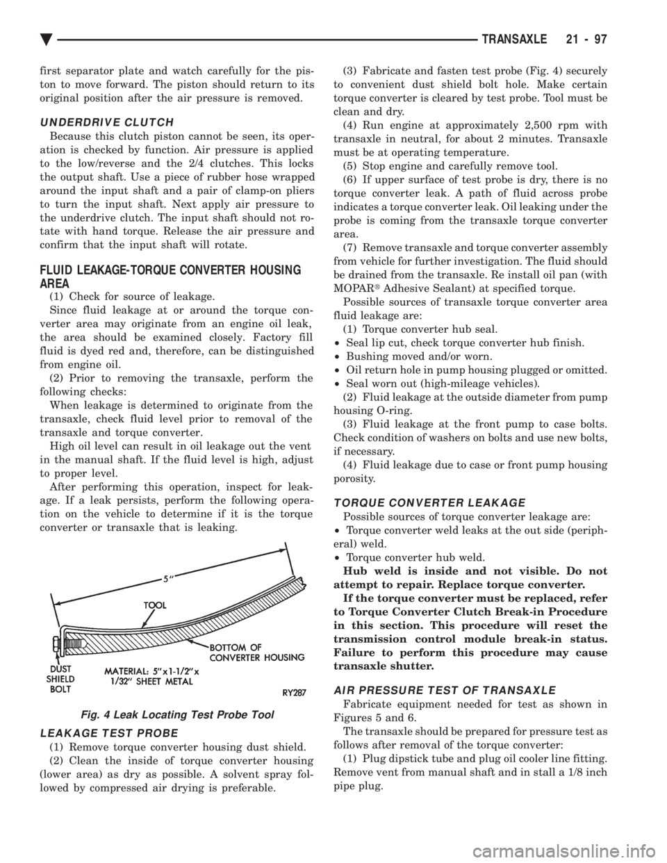
lowed by compressed air drying is preferable. (3) Fabricate and fasten test probe (Fig. 4) securely
to convenient dust shield bolt hole. Make certain
torque converter is cleared by test probe. Tool must be
clean and dry. (4) Run engine at approximately 2,500 rpm with
transaxle in neutral, for about 2 minutes. Transaxle
must be at operating temperature. (5) Stop engine and carefully remove tool.
(6) If upper surface of test probe is dry, there is no
torque converter leak. A path of fluid across probe
indicates a torque converter leak. Oil leaking under the
probe is coming from the transaxle torque converter
area. (7) Remove transaxle and torque converter assembly
from vehicle for further investigation. The fluid should
be drained from the transaxle. Re install oil pan (with
MOPAR tAdhesive Sealant) at specified torque.
Possible sources of transaxle torque converter area
fluid leakage are: (1) Torque converter hub seal.
² Seal lip cut, check torque converter hub finish.
² Bushing moved and/or worn.
² Oil return hole in pump housing plugged or omitted.
² Seal worn out (high-mileage vehicles).
(2) Fluid leakage at the outside diameter from pump
housing O-ring. (3) Fluid leakage at the front pump to case bolts.
Check condition of washers on bolts and use new bolts,
if necessary. (4) Fluid leakage due to case or front pump housing
porosity.
TORQUE CONVERTER LEAKAGE
Possible sources of torque converter leakage are:
² Torque converter weld leaks at the out side (periph-
eral) weld.
² Torque converter hub weld.
Hub weld is inside and not visible. Do not
attempt to repair. Replace torque converter. If the torque converter must be replaced, refer
to Torque Converter Clutch Break-in Procedure
in this section. This procedure will reset the
transmission control module break-in status.
Failure to perform this procedure may cause
transaxle shutter.
AIR PRESSURE TEST OF TRANSAXLE
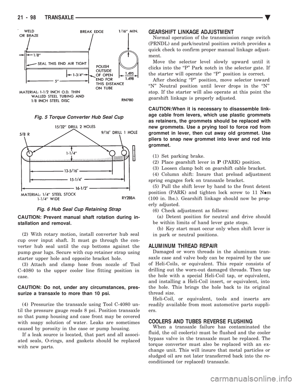
Fabricate equipment needed for test as shown in
Figures 5 and 6. The transaxle should be prepared for pressure test as
follows after removal of the torque converter: (1) Plug dipstick tube and plug oil cooler line fitting.
Remove vent from manual shaft and in stall a 1/8 inch
pipe plug.Fig. 4 Leak Locating Test Probe Tool
Ä TRANSAXLE 21 - 97
Page 2058 of 2438
CAUTION: Prevent manual shaft rotation during in-
stallation and removal. (2) With rotary motion, install converter hub seal
cup over input shaft. It must go through the con-
verter hub seal until the cup bottoms against the
pump gear lugs. Secure with cup retainer strap using
starter upper hole and opposite bracket hole. (3) Attach and clamp hose from nozzle of Tool
C-4080 to the upper cooler line fitting position in
case.
CAUTION: Do not, under any circumstances, pres-
surize a transaxle to more than 10 psi.
(4) Pressurize the transaxle using Tool C-4080 un-
til the pressure gauge reads 8 psi. Position transaxle
so that pump housing and case front may be covered
with soapy solution of water. Leaks are sometimes
caused by porosity in the case or pump housing. If a leak source is located, that part and all associ-
ated seals, O-rings, and gaskets should be replaced
with new parts.
GEARSHIFT LINKAGE ADJUSTMENT
Normal operation of the transmission range switch
(PRNDL) and park/neutral position switch provides a
quick check to confirm proper manual linkage adjust-
ment. Move the selector level slowly upward until it
clicks into the ``P'' Park notch in the selector gate. If
the starter will operate the ``P'' position is correct. After checking ``P'' position, move selector toward
``N'' Neutral position until lever drops in the ``N''
stop. If the starter will also operate at this point the
gearshift linkage is properly adjusted.
CAUTION:When it is necessary to disassemble link-
age cable from levers, which use plastic grommets
as retainers, the grommets should be replaced with
new grommets. Use a prying tool to force rod from
grommet in lever, then cut away old grommet. Use
pliers to snap new grommet into lever and rod into
grommet.
(1) Set parking brake.
(2) Place gearshift lever in P(PARK) position.
(3) Loosen clamp bolt on gearshift cable bracket.
(4) Column shift: Insure that preload adjustment
spring engages fork on transaxle bracket. (5) Pull the shift lever by hand to the front detent
position (PARK) and tighten lock screw to 11 N Im
(100 in. lbs.). Gearshift linkage should now be prop-
erly adjusted. (6) Check adjustment as follows:(a) Detent position for neutral and drive should
be within limits of hand lever gate stops. (b) Key start must occur only when shift lever is
in park or neutral positions.
ALUMINUM THREAD REPAIR
Damaged or worn threads in the aluminum tran-
saxle case and valve body can be repaired by the use
of Heli-Coils, or equivalent. This repair consists of
drilling out the worn-out damaged threads. Then tap
the hole with a special Heli-Coil tap, or equivalent,
and installing a Heli-Coil insert, or equivalent, into
the hole. This brings the hole back to its original
thread size. Heli-Coil, or equivalent, tools and inserts are
readily available from most automotive parts suppli-
ers.
COOLERS AND TUBES REVERSE FLUSHING
When a transaxle failure has contaminated the
fluid, the oil cooler(s) must be flushed and the cooler
bypass valve in the transaxle must be replaced. The
torque converter must also be replaced with an ex-
change unit. This will insure that metal particles or
sludged oil are not later transferred back into the re-
conditioned (or replaced) transaxle.
Fig. 5 Torque Converter Hub Seal Cup
Fig. 6 Hub Seal Cup Retaining Strap
21 - 98 TRANSAXLE Ä
Page 2060 of 2438
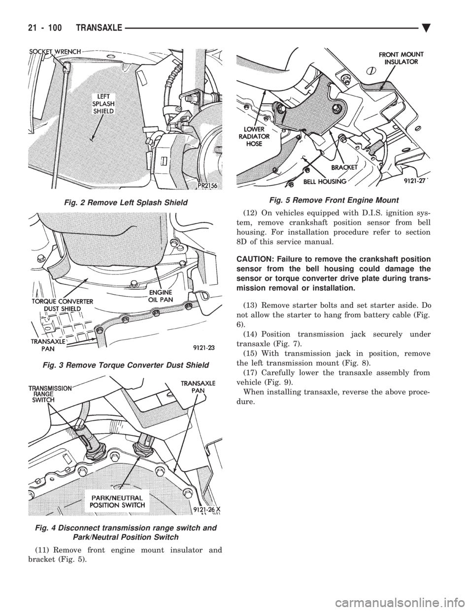
(11) Remove front engine mount insulator and
bracket (Fig. 5). (12) On vehicles equipped with D.I.S. ignition sys-
tem, remove crankshaft position sensor from bell
housing. For installation procedure refer to section
8D of this service manual.
CAUTION: Failure to remove the crankshaft position
sensor from the bell housing could damage the
sensor or torque converter drive plate during trans-
mission removal or installation.
(13) Remove starter bolts and set starter aside. Do
not allow the starter to hang from battery cable (Fig.
6). (14) Position transmission jack securely under
transaxle (Fig. 7). (15) With transmission jack in position, remove
the left transmission mount (Fig. 8). (17) Carefully lower the transaxle assembly from
vehicle (Fig. 9). When installing transaxle, reverse the above proce-
dure.
Fig. 2 Remove Left Splash Shield
Fig. 3 Remove Torque Converter Dust Shield
Fig. 4 Disconnect transmission range switch and Park/Neutral Position Switch
Fig. 5 Remove Front Engine Mount
21 - 100 TRANSAXLE Ä
Page 2157 of 2438
BODY
CONTENTS
page page
AA-VEHICLE BODY COMPONENT SERVICE . . . 11
AC-VEHICLE BODY COMPONENT SERVICE . . . 37
AG-VEHICLE BODY COMPONENT SERVICE . . . 52
AJ-VEHICLE BODY COMPONENT SERVICE . . . 71
AJ/27-VEHICLE CONVERTIBLE BODYCOMPONENT SERVICE ................. 86
AP-VEHICLE BODY COMPONENT SERVICE . . . 97
AP/17-VEHICLE CONVERTIBLE BODY COMPONENT SERVICE ................. 117 AY-VEHICLE BODY COMPONENT SERVICE . . 133
BODY DIAGNOSTIC PROCEDURES .......... 2
GENERAL SERVICE INFORMATION .......... 1
PAINT ................................. 4
POWER SUNROOF ....................... 6
WINDSHIELD ........................... 9
GENERAL SERVICE INFORMATION
VEHICLE IDENTIFICATION
Throughout this group, references to the Chrysler
Corporation vehicle family identification code is used
when describing a procedure that is unique to that
vehicle. Refer to Introduction Group of this manual for
detailed information on vehicle identification. If a
procedure is common to all vehicles covered in this
manual, no reference will be made to a vehicle family
code.
SAFETY PRECAUTIONS AND WARNINGS
WARNING: WHEN SERVICING A VEHICLE EQUIPPED
WITH AIRBAG RESTRAINT SYSTEM, REVIEW ALL
PRECAUTIONS IN GROUP 8M, RESTRAINT SYS-
TEMS. PERSONAL INJURY CAN RESULT. EYE PROTECTION SHOULD BE USED WHEN SER-
VICING GLASS COMPONENTS. PERSONAL INJURY
CAN RESULT. USE A BREATHING FILTER WHEN SPRAYING
PAINT OR SOLVENTS IN A CONFINED AREA. PER-
SONAL INJURY CAN RESULT. AVOID PROLONGED SKIN CONTACT WITH PETRO-
LEUM OR ALCOHOL BASED CLEANING SOLVENTS.
PERSONAL INJURY CAN RESULT. DO NOT VENTURE UNDER A HOISTED VEHICLE
THAT IS NOT PROPERLY SUPPORTED ON SAFETY
STANDS. PERSONAL INJURY CAN RESULT.
CAUTION: When holes must be drilled or punched in
a inner body panel, verify depth of space to the outer
body panel, electrical wiring, or other components.
Damage to vehicle can result. Do not use abrasive chemicals or compounds on
painted surfaces. Damage to finish can result. Do not use harsh alkaline based cleaning solvents
on painted or upholstered surfaces. Damage to finish
or color can result. Do not hammer or pound on plastic trim panel
attaching fasteners when servicing interior trim. Plas-
tic panel can break.
Chrysler Corporation uses many different types of
push-in fasteners to secure the interior and exterior
trim to the body . Most of these fasteners can be reused
to assemble the trim during various repair procedures.
At times a push-in fastener cannot be removed without
damaging the fastener or the component it is holding.
If it is not possible to remove a fastener without
damaging a component or body, cut or brake the
fastener and use a new one when installing the com-
ponent. Never pry or pound on a plastic or press-board
trim component. Using a suitable fork-type prying
device, pry the fastener from the retaining hole behind
the component being removed. When installing, verify
that fastener is aligned with the retaining hole, by
hand, push directly on or over the fastener until it
seats. Apply a low force pull to the panel to verify that
it is secure. When it is necessary to remove components to service
another, it should not be necessary to apply excessive
force or bend a component to remove it. Before damag-
ing a component to be reused, verify there is no hidden
fasteners or captured edges holding the component in.
Often a fastener is hidden by carpeting nap or trim
plugs.
Ä BODY 23 - 1