1993 CHEVROLET PLYMOUTH ACCLAIM ECU
[x] Cancel search: ECUPage 729 of 2438
(4) Reverse battery leads (steps 1 and 2 above) and
window should now move. If window does not move,
remove motor. See below for motor removal from ve-
hicle. (5) If window moved completely up or down, motor
should be reversed one more time (reverse leads from
step 4) to complete a full window travel inspection.
GEAR AND PINION REPLACEMENT AND
LUBRICATION
The window glass and mechanism have been found
to move freely. The window motor works. But the
glass does not move up or down. The motor gear and
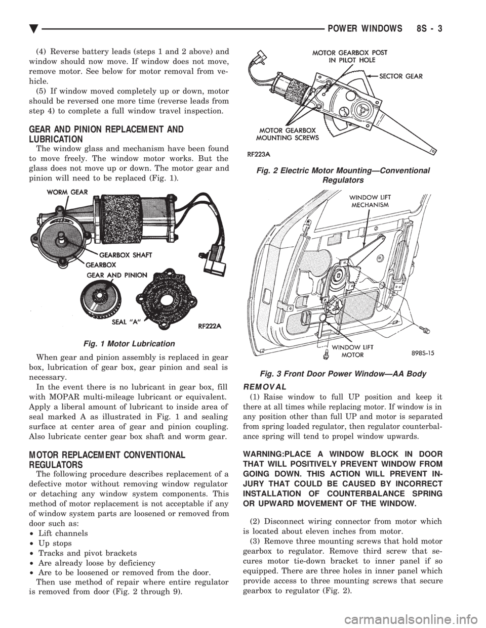
pinion will need to be replaced (Fig. 1).
When gear and pinion assembly is replaced in gear
box, lubrication of gear box, gear pinion and seal is
necessary. In the event there is no lubricant in gear box, fill
with MOPAR multi-mileage lubricant or equivalent.
Apply a liberal amount of lubricant to inside area of
seal marked A as illustrated in Fig. 1 and sealing
surface at center area of gear and pinion coupling.
Also lubricate center gear box shaft and worm gear.
MOTOR REPLACEMENT CONVENTIONAL
REGULATORS
The following procedure describes replacement of a
defective motor without removing window regulator
or detaching any window system components. This
method of motor replacement is not acceptable if any
of window system parts are loosened or removed from
door such as:
² Lift channels
² Up stops
² Tracks and pivot brackets
² Are already loose by deficiency
² Are to be loosened or removed from the door.
Then use method of repair where entire regulator
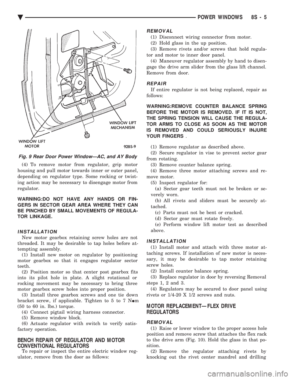
is removed from door (Fig. 2 through 9).
REMOVAL
(1) Raise window to full UP position and keep it
there at all times while replacing motor. If window is in
any position other than full UP and motor is separated
from spring loaded regulator, then regulator counterbal-
ance spring will tend to propel window upwards.
WARNING:PLACE A WINDOW BLOCK IN DOOR
THAT WILL POSITIVELY PREVENT WINDOW FROM
GOING DOWN. THIS ACTION WILL PREVENT IN-
JURY THAT COULD BE CAUSED BY INCORRECT
INSTALLATION OF COUNTERBALANCE SPRING
OR UPWARD MOVEMENT OF THE WINDOW.
(2) Disconnect wiring connector from motor which
is located about eleven inches from motor. (3) Remove three mounting screws that hold motor
gearbox to regulator. Remove third screw that se-
cures motor tie-down bracket to inner panel if so
equipped. There are three holes in inner panel which
provide access to three mounting screws that secure
gearbox to regulator (Fig. 2).
Fig. 1 Motor Lubrication
Fig. 2 Electric Motor MountingÐConventional Regulators
Fig. 3 Front Door Power WindowÐAA Body
Ä POWER WINDOWS 8S - 3
Page 731 of 2438
(4) To remove motor from regulator, grip motor
housing and pull motor towards inner or outer panel,
depending on regulator type. Some rocking or twist-
ing action may be necessary to disengage motor from
regulator.
WARNING:DO NOT HAVE ANY HANDS OR FIN-
GERS IN SECTOR GEAR AREA WHERE THEY CAN
BE PINCHED BY SMALL MOVEMENTS OF REGULA-
TOR LINKAGE.
INSTALLATION
New motor gearbox retaining screw holes are not
threaded. It may be desirable to tap holes before at-
tempting assembly. (1) Install new motor on regulator by positioning
motor gearbox so that it engages regulator sector
teeth. (2) Position motor so that center post gearbox fits
into its pilot hole in plate. A slight rotational or
rocking movement may be necessary to bring three
motor gearbox screw holes into proper position. (3) Install three gearbox screws and one tie down
bracket screw, if applicable. Tighten to 5 to 7 N Im
(50 to 60 in. lbs.) torque. (4) Connect pigtail wiring harness connector.
(5) Remove window block.
(6) Actuate regulator with switch to verify satis-
factory operation.
BENCH REPAIR OF REGULATOR AND MOTOR
CONVENTIONAL REGULATORS
To repair or inspect the entire electric window reg-
ulator, remove from the door as follows:
REMOVAL
(1) Disconnect wiring connector from motor.
(2) Hold glass in the up position.
(3) Remove rivets and/or screws that hold regula-
tor and motor to inner door panel. (4) Maneuver regulator assembly by hand to disen-
gage the drive arm slider from the glass lift channel.
Remove from door.
REPAIR
If entire regulator is not being replaced, repair as
follows:
WARNING:REMOVE COUNTER BALANCE SPRING
BEFORE THE MOTOR IS REMOVED. IF IT IS NOT,
THE SPRING TENSION WILL CAUSE THE REGULA-
TOR ARMS TO CLOSE AS SOON AS THE MOTOR
IS REMOVED AND COULD SERIOUSLY INJURE
YOUR FINGERS .
(1) Remove regulator as described above.
(2) Secure regulator in vise to prevent sector gear
from rotating. (3) Remove counter balance spring.
(4) Remove three motor attaching screws and re-
move motor. (5) Inspect regulator for:(a) Sector gear teeth must not be broken or se-
verely worn. (b) All rivets and sliders must be securely at-
tached. (c) Parts must not be bent or cracked.
(d) Sector gear must rotate freely.
(e) Perform window lift motor test as described
above.
INSTALLATION
(1) Install motor and attach with three motor at-
taching screws. If installation of new motor is neces-
sary, it may be desirable to tap motor retaining
screw holes. (2) Install counter balance spring.
(3) Replace regulator in door by reversing Removal
steps 1, 2 and 3. (4) Regulators may be secured to door panel using
rivets or 1/4-20 X 1/2 screws and nuts.
MOTOR REPLACEMENTÐFLEX DRIVE
REGULATORS
REMOVAL
(1) Raise or lower window to the proper access hole
position and remove screw that attaches the flex rack
to the drive arm (Fig. 10). Hold the glass in that po-
sition. (2) Remove the regulator attaching rivets by
knocking out the rivet center mandrel and drilling
Fig. 9 Rear Door Power WindowÐAC, and AY Body
Ä POWER WINDOWS 8S - 5
Page 734 of 2438

INSTALLATION
(1) Install motor into housing with one stud and in
center of housing to secure motor to housing. (2) Before installing new spring, power the motor
into the full-up position. (3) Replace assist spring on cable housing. Wind
spring counter clockwise 3 1/2 turns on the left door.
The right door, wind spring clockwise 3 1/2 turns
(Fig. 19).
(4) Install the other two studs and nuts and
tighten to 4 to 5 M Im (35 to 45 in. lbs.) torque.
(5) Inspect that cables are not twisted prior to in-
stalling motor and housing into door.
QUARTER WINDOW REPLACEMENTÐAJ BODY
For steps (1) through (5) refer to Group 23, Body,
for complete procedures. (1) Remove the folding top sling well assembly.
(2) Remove the quarter trim upper moldings.
(3) Remove the cowl trim and scuff plate panels.
(4) Remove the rear seat cushion.
(5) Remove the quarter trim and rear seat back as-
sembly. (6) Remove quarter windows assembly (Fig. 20).
Fig. 16 Separating Motor from Housing
Fig. 17 Cable/Drum and Motor
Fig. 18 Assist Spring Cover
Fig. 19 Wind Assist Spring Cover
Fig. 20 Power Quarter WindowÐAJ Body
8S - 8 POWER WINDOWS Ä
Page 755 of 2438
When a fusible link blows it is important to find
out what the problem is. They are placed in the sys-
tem for protection against shorts. Which can be
caused by a component failure or wiring failures. Do
not just replace the fusible link to correct the
problem. When diagnosing a faulty fusible link it is impor-
tant to check the wire carefully. In some instances
the link may be blown and it will not show through
the insulation, the wire should be checked over its
entire length for internal breaks. (1) Disconnect battery negative cable.
(2) Cut out the blown portion of the fusible link.
(3) Strip 1 inch of insulation from each end of the
existing fusible link. (4) Place a piece of heat shrink tubing over one
side of the fusible link. Make sure the tubing will be
long enough to cover and seal the entire repair area. (5) Cut a replacement piece of fusible link approx-
imately two inches longer than the piece removed. (6) Remove one inch of insulation from each end of
the replacement fusible link. (7) Spread the strands of wire apart on each of the
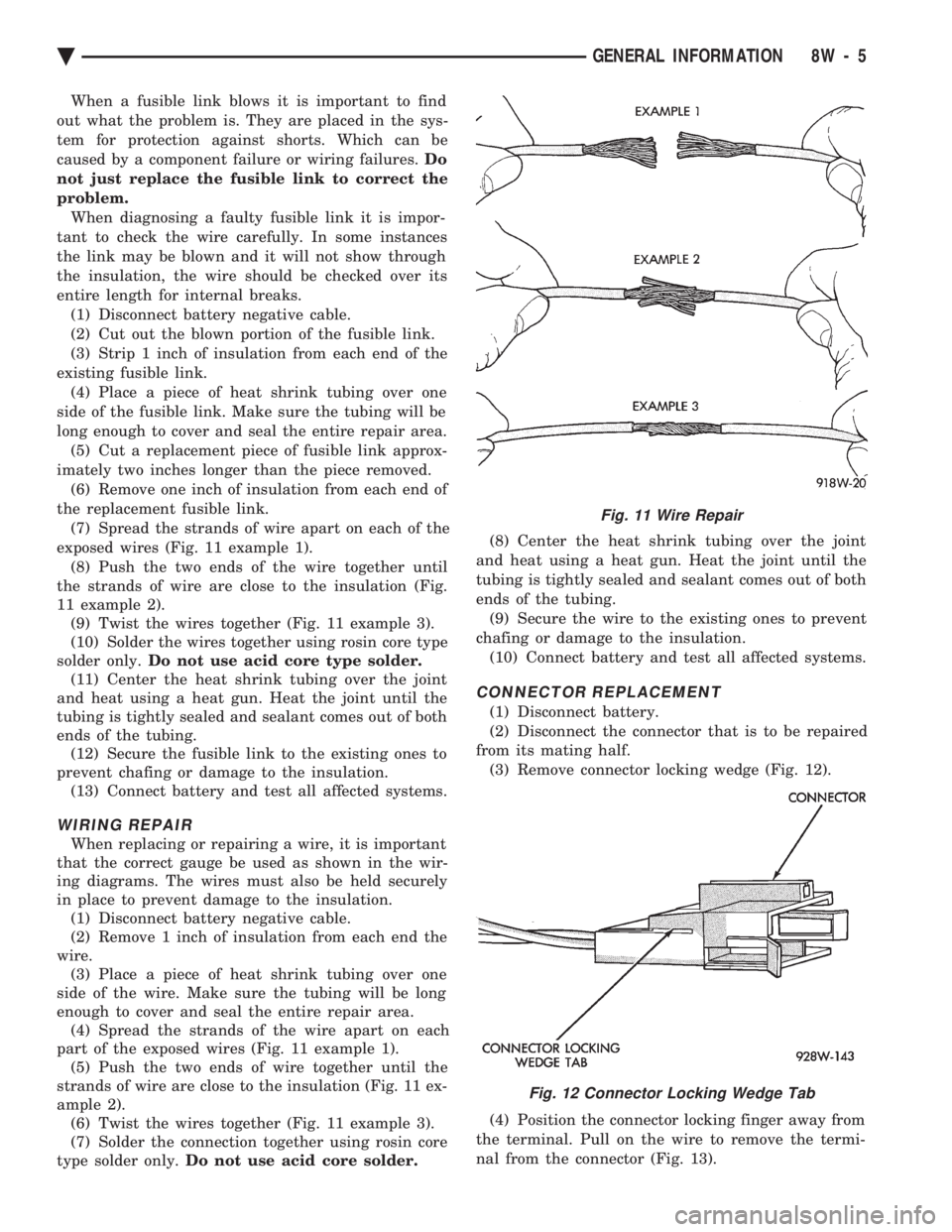
exposed wires (Fig. 11 example 1). (8) Push the two ends of the wire together until
the strands of wire are close to the insulation (Fig.
11 example 2). (9) Twist the wires together (Fig. 11 example 3).
(10) Solder the wires together using rosin core type
solder only. Do not use acid core type solder.
(11) Center the heat shrink tubing over the joint
and heat using a heat gun. Heat the joint until the
tubing is tightly sealed and sealant comes out of both
ends of the tubing. (12) Secure the fusible link to the existing ones to
prevent chafing or damage to the insulation. (13) Connect battery and test all affected systems.
WIRING REPAIR
When replacing or repairing a wire, it is important
that the correct gauge be used as shown in the wir-
ing diagrams. The wires must also be held securely
in place to prevent damage to the insulation. (1) Disconnect battery negative cable.
(2) Remove 1 inch of insulation from each end the
wire. (3) Place a piece of heat shrink tubing over one
side of the wire. Make sure the tubing will be long
enough to cover and seal the entire repair area. (4) Spread the strands of the wire apart on each
part of the exposed wires (Fig. 11 example 1). (5) Push the two ends of wire together until the
strands of wire are close to the insulation (Fig. 11 ex-
ample 2). (6) Twist the wires together (Fig. 11 example 3).
(7) Solder the connection together using rosin core
type solder only. Do not use acid core solder. (8) Center the heat shrink tubing over the joint
and heat using a heat gun. Heat the joint until the
tubing is tightly sealed and sealant comes out of both
ends of the tubing. (9) Secure the wire to the existing ones to prevent
chafing or damage to the insulation. (10) Connect battery and test all affected systems.
CONNECTOR REPLACEMENT
(1) Disconnect battery.
(2) Disconnect the connector that is to be repaired
from its mating half. (3) Remove connector locking wedge (Fig. 12).
(4) Position the connector locking finger away from
the terminal. Pull on the wire to remove the termi-
nal from the connector (Fig. 13).
Fig. 11 Wire Repair
Fig. 12 Connector Locking Wedge Tab
Ä GENERAL INFORMATION 8W - 5
Page 1067 of 2438
Wiring Diagram
Name Sheet Number
Blower Slide Control .........................51
Illumination Lamp ...........................51
Resistor .................................51
Horn System ............................ .63, 64
Clockspring ...............................63
Horn (Hi-note) .............................63
Horn (Lo-note) .............................63
Horn Relay ...............................63
Horn Switch ..............................63
Idle Air Control Motor .................... .14, 21, 26
Ignition Switch .............................4,11
Injectors ............................ .15, 20, 24
Illuminated Entry System ........................91
Left Front Door Courtesy Lamp ..................91
Left Front Door Illuminated Entry Switch ............91
Right Front Door Courtesy Lamp .................91
Right Front Door Illuminated Entry Switch ...........91
Instrument Panel to Multi-Function Switch Wiring .......180
Instrument Panel Ground System ...................86
Interface Grommet ............................58
Intermittent Wiper System .................... .61, 62
Intermittent Wiper Motor ......................62
Intermittent Wiper Switch ......................61
Washer Pump Motor .........................61
Windshield Washer Low Fluid Level Sensor ...........61
Key Cylinders .......................... .131, 135
Key-In Switch .......................... .104, 107
Keyless Entry Connectors ...................... .208
Lamp Outage Module ...................... .96, 209
Lamps Ash Receiver Lamp ........................ .111
Back-Up Lamps ................ .161, 162, 163, 164
Center High Mounted Stop Lamp ......161, 162, 163, 164
Cornering Lamp Left ...............74, 77, 80, 82, 84
Cornering Lamp Right ..............73, 75, 78, 81, 83
Courtesy Lamps ................... .87, 88, 89, 90
Deck Lid Ajar Warning Lamp ....................95
Door Ajar Lamps ...........................95
Door Courtesy Lamp ................ .87, 88, 90, 91
Glove Box Lamp .......................... .111
Halo Lamp .......................... .104, 106
Headlamp-Left ............... .70, 72, 74, 80, 82, 84
Headlamp-Right ............ .69, 71, 73, 75, 78, 81, 83
Headlamp Switch Lamp .......................85
Illuminated Entry Lamps .......................91
Illumination Lamp ..................... .51, 53, 55
License Lamp .................. .161, 162, 163, 164
Low Engine Oil Pressure Lamp .............30, 31, 32
Low Windshield Washer Fluid Warning Lamp .........95
Parking/Turn Lamp-Left ........70, 72, 74, 77, 80, 82, 84
Parking/Turn Lamp-Right .......69, 71, 73, 75, 78, 81, 83
Park Lamp-Left ............................74
Park Lamp-Right ...........................73
Reading Lamps ............................90
Security Lamp ..................... .128, 132, 136
Side Marker Lamp-Left Front ............70, 72, 82, 84
Side Marker Lamp-Right Front ...........69, 71, 81, 83Wiring Diagram
Name Sheet Number
Side Marker Lamp-Left Rear ................161, 163
Side Marker Lamp-Right Rear ...............162, 164
Tail, Stop/Turn Signal Lamp-Left Rear ..........161, 163
Tail, Stop/Turn Signal Lamp-Right Rear .........162, 164
Transmission Range Lamp .....................85
Trunk Lamp ...............................90
Turn Signal Lamp-Left Front ...............74, 77, 80
Turn Signal Lamp-Right Front ..............73, 75, 78
Underhood Lamp ......................... .159
Vanity Mirror ..............................89
Visor Lamp ...............................89
Left Body to Instrument Panel Wiring ............190, 191
Left Front Door Jamb Switch .....................87
Left Rear Door Jamb Switch ......................87
MAP Sensor .......................... .18, 21, 26
Mechanical Cluster Printed Circuit Board .............167
Mechanical Cluster Printed Circuit Board Connectors ......166
Memory Power Seat & Mirror Connector .............204
Memory Power Seat System ...........151, 152, 153, 154
Circuit Breaker ........................... .153
Left Power Seat Motors ..................... .153
Left Power Seat Switch ...................... .152
Left Power Seat Switch Insulator ................152
Left Recliner Motor ........................ .154
Memory Module ................ .151, 152, 153, 154
Recliner Position Sense Resistor .................154
Recliner Seat Switch ....................... .152
Relay Bank ............................. .153
Seat Memory Selector Switch ...................151
Seat Track Position Sense Resistor ...............154
Memory Power Seat System Connectors .............205
Message Center Connector ..................... .207
Mirror-Heated ....................... .143, 144, 146
Mirror-Power .................... .143, 144, 145, 146
Modules Airbag System Diagnostic Module .................57
Air Suspension Control Module ................41, 43
ATC Power Module ........................ .115
Daytime Running Lamp Module ...........72, 76, 79, 84
Lamp Outage Module .................... .96, 209
Mirror Memory Module .................. .143, 144
Power Seat Memory Module .........151, 152, 153, 154
Powertrain Control Module ........14, 15, 16, 17, 18, 19,
20, 21, 22, 23, 24, 25, 26, 27, 28, 29, 37
Relay Module ............................ .171
Remote Keyless Entry Module ...............141, 142
Security Alarm Module ......127, 128, 129, 130, 131, 132,
133, 134, 135, 136, 137, 138
Sunroof Control .......................... .147
Transmission Control Module ...............33, 34, 35
Motors ABS Pump Motor ...........................46
Antenna Motor ........................... .118
Blower-A/C ............................ .53, 55
Blower ATC ............................. .115
Blower-Heater .............................51
Compressor Motor ....................... .40, 42
Ä WIRING DIAGRAMS AC-AY BODY 8W - 317
Page 1069 of 2438
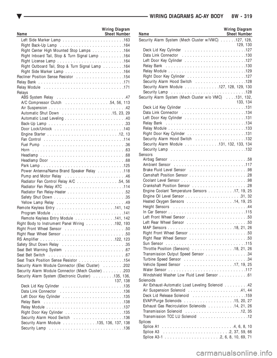
Wiring Diagram
Name Sheet Number
Left Side Marker Lamp ...................... .163
Right Back-Up Lamp ....................... .164
Right Center High Mounted Stop Lamps ............164
Right Inboard Tail, Stop & Turn Signal Lamp .........164
Right License Lamp ........................ .164
Right Outboard Tail, Stop & Turn Signal Lamp ........164
Right Side Marker Lamp ..................... .164
Recliner Position Sense Resistor ..................154
Relay Bank ............................... .171
Relay Module ............................. .171
Relays ABS System Relay ..........................47
A/C Compressor Clutch .................54, 56, 113
Air Suspension .............................42
Automatic Shut Down .................. .15, 23, 29
Automatic Load Leveling .......................40
Back-Up Lamp .............................33
Door Lock/Unlock ......................... .140
Engine Starter .......................... .12, 13
Fan Control ............................. .114
Fuel Pump ...............................36
Horn ...................................63
Headlamp ................................68
Headlamp Door ............................68
Park Lamp .............................. .125
Power Antenna/Name Brand Speaker Relay ..........118
Pump and Motor Relay .......................46
Radiator Fan Control Relay A/C ................54, 56
Radiator Fan Relay ATC ..................... .114
Radiator Fan Relay-Heater ......................52
Safety Shut Down ...........................35
Yellow Lamp Relay ..........................49
Remote Keyless Entry ..................... .141, 142
Program Module .......................... .141
Remote Keyless Entry Module ...............141, 142
Right Body to Instrument Panel Wiring ...........192, 193
Right Front Wheel Sensor .......................50
Right Rear Wheel Sensor ........................50
RS Amplifier ........................... .122, 123
Safety Shut Down Relay ........................35
Seat Belt Warning System .......................67
Seat Belt Switch .............................67
Seat Track Position Sense Resistor .................154
Security Alarm Module Connector (Elec Cluster) ........202
Security Alarm Module Connector (Mech Cluster) ........203
Security Alarm System (Electronic Cluster) ........135, 136,
137, 138
Deck Lid Key Cylinder ...................... .135
Data Link Connector ....................... .136
Left Door Key Cylinder ...................... .135
Relay Bank ............................. .138
Relay Module ............................ .137
Right Door Key Cylinder ..................... .135
Security Alarm Hood Switch ...................136
Security Alarm Module .............135, 136, 137, 138
Security Lamp ........................... .136Wiring Diagram
Name Sheet Number
Security Alarm System (Mech Cluster w/VMC) ......127, 128,
129, 130
Deck Lid Key Cylinder ...................... .127
Data Link Connector ....................... .130
Left Door Key Cylinder ...................... .127
Relay Bank ............................. .130
Relay Module ............................ .129
Right Door Key Cylinder ..................... .127
Security Alarm Hood Switch ...................128
Security Alarm Module .............127, 128, 129, 130
Security Lamp ........................... .128
Security Alarm System (Mech Cluster w/o VMC) . . . .131, 132,
133, 134
Deck Lid Key Cylinder ...................... .131
Data Link Connector ....................... .134
Left Door Key Cylinder ...................... .131
Relay Bank ............................. .134
Relay Module ............................ .133
Right Door Key Cylinder ..................... .131
Security Alarm Hood Switch ...................132
Security Alarm Module .............131, 132, 133, 134
Security Lamp ........................... .132
Sensors Airbag Sensor .............................58
Ambient Sensor .......................... .117
Brake Fluid Level Sensor ......................98
Camshaft Position Sensor ......................28
Coolant Level Sensor .........................98
Crankshaft Position Sensor .....................28
Engine Coolant Temperature Sensors ..........17, 19, 25
Engine Oil Level Sensor .................... .31, 32
Heated Oxygen Sensors ................. .14, 19, 25
Height Sensors ............................44
In Car Senso r............................ .115
Left Front Wheel Sensor .......................50
Left Rear Wheel Sensor .......................50
MAP Sensors ........................ .18, 21, 26
Right Front Wheel Sensor ......................50
Right Rear Wheel Sensor ......................50
Sun Sensor ............................. .115
Throttle Position (Sensors) ................18, 21, 26
Transmission Output Speed Sensor ................34
Turbine Speed Sensor ........................34
Vehicle Speed Sensor .................. .17, 19, 25
Water Sensor ............................ .117
Windshield Washer Low Fluid Level Sensor ...........61
Solenoids Air Exhaust-Automatic Load Leveling Solenoid .........42
Air Suspension Solenoid ................... .41, 44
Deck Lid Release Solenoid ................... .159
EVAP/Purge Solenoids .................. .15, 20, 27
Exhaust Gas Recirculation Solenoids ..........14, 21, 26
Transmission Solenoid .................... .12, 35
Transmission TCC LU Solenoid ..................12
Splices Splice A1 ...........................4,6,8,10
Splice A3 .........................2,37,59,66
Splice A3-1 .....................2,6,8,10,69,71
Ä WIRING DIAGRAMS AC-AY BODY 8W - 319
Page 1071 of 2438
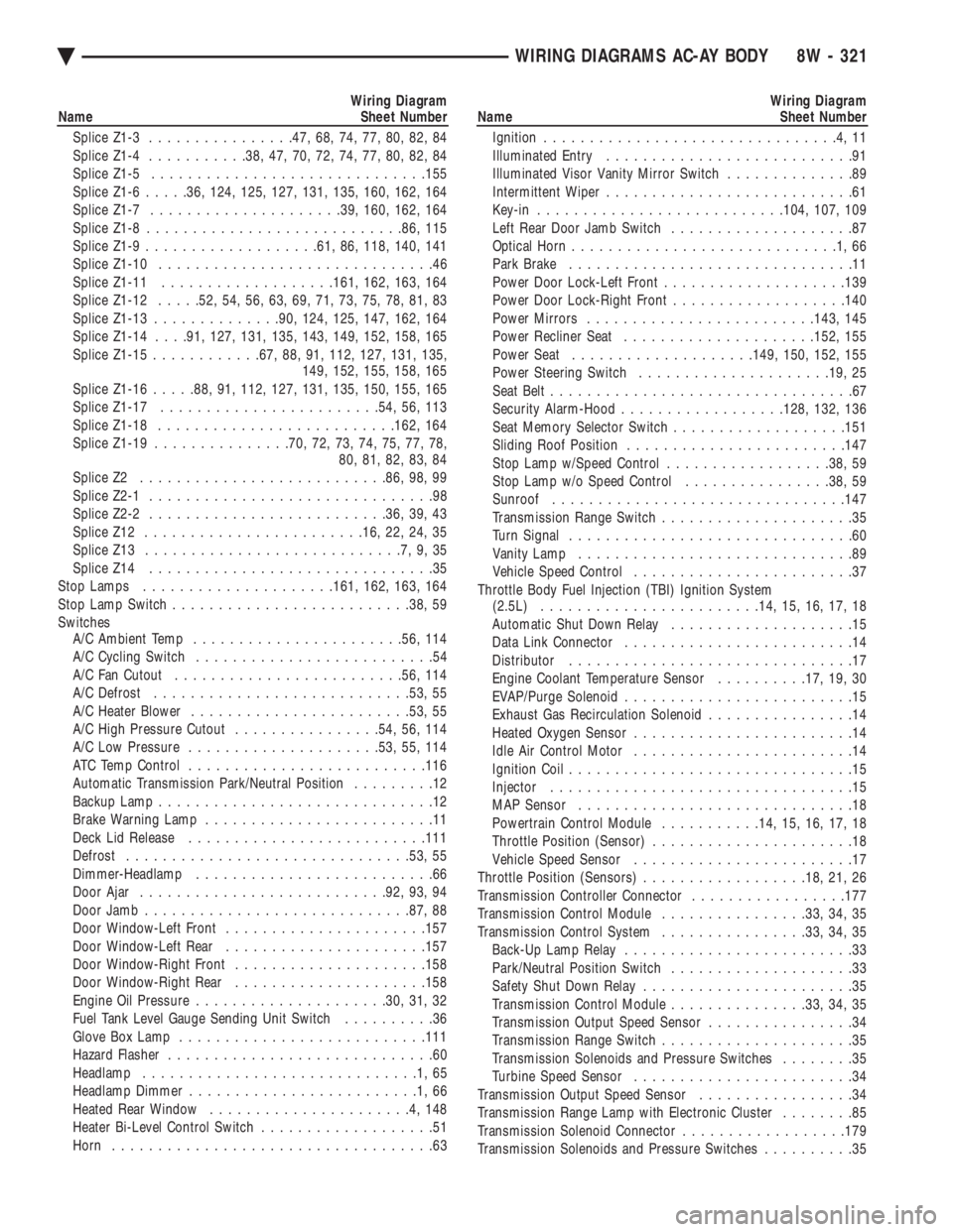
Wiring Diagram
Name Sheet Number
Splice Z1-3 ............... .47, 68, 74, 77, 80, 82, 84
Splice Z1-4 .......... .38, 47, 70, 72, 74, 77, 80, 82, 84
Splice Z1-5 ............................. .155
Splice Z1-6 .....36, 124, 125, 127, 131, 135, 160, 162, 164
Splice Z1-7 .................... .39, 160, 162, 164
Splice Z1-8 ........................... .86, 115
Splice Z1-9 .................. .61, 86, 118, 140, 141
Splice Z1-10 ..............................46
Splice Z1-11 .................. .161, 162, 163, 164
Splice Z1-12 .....52, 54, 56, 63, 69, 71, 73, 75, 78, 81, 83
Splice Z1-13 ............. .90, 124, 125, 147, 162, 164
Splice Z1-14 . . . .91, 127, 131, 135, 143, 149, 152, 158, 165
Splice Z1-15 ........... .67, 88, 91, 112, 127, 131, 135,
149, 152, 155, 158, 165
Splice Z1-16 .....88, 91, 112, 127, 131, 135, 150, 155, 165
Splice Z1-17 ....................... .54, 56, 113
Splice Z1-18 ......................... .162, 164
Splice Z1-19 .............. .70, 72, 73, 74, 75, 77, 78,
80, 81, 82, 83, 84
Splice Z2 .......................... .86, 98, 99
Splice Z2-1 ...............................98
Splice Z2-2 ......................... .36, 39, 43
Splice Z12 ....................... .16, 22, 24, 35
Splice Z13 ............................7,9,35
Splice Z14 ...............................35
Stop Lamps .................... .161, 162, 163, 164
Stop Lamp Switch ......................... .38, 59
Switches A/C Ambient Temp ...................... .56, 114
A/C Cycling Switch ..........................54
A/C Fan Cutout ........................ .56, 114
A/C Defrost ........................... .53, 55
A/C Heater Blower ....................... .53, 55
A/C High Pressure Cutout ................54, 56, 114
A/C Low Pressure .................... .53, 55, 114
ATC Temp Control ......................... .116
Automatic Transmission Park/Neutral Position .........12
Backup Lamp ..............................12
Brake Warning Lamp .........................11
Deck Lid Release ......................... .111
Defrost .............................. .53, 55
Dimmer-Headlamp ..........................66
Door Ajar .......................... .92, 93, 94
Door Jamb ............................ .87, 88
Door Window-Left Front ..................... .157
Door Window-Left Rear ..................... .157
Door Window-Right Front .................... .158
Door Window-Right Rear .................... .158
Engine Oil Pressure .................... .30, 31, 32
Fuel Tank Level Gauge Sending Unit Switch ..........36
Glove Box Lamp .......................... .111
Hazard Flasher .............................60
Headlamp ..............................1,65
Headlamp Dimmer .........................1,66
Heated Rear Window ......................4,148
Heater Bi-Level Control Switch ...................51
Horn ...................................63Wiring Diagram
Name Sheet Number
Ignition ................................4,11
Illuminated Entry ...........................91
Illuminated Visor Vanity Mirror Switch ..............89
Intermittent Wiper ...........................61
Key-in .......................... .104, 107, 109
Left Rear Door Jamb Switch ....................87
Optical Horn .............................1,66
Park Brake ...............................11
Power Door Lock-Left Front ................... .139
Power Door Lock-Right Front ...................140
Power Mirrors ........................ .143, 145
Power Recliner Seat .................... .152, 155
Power Seat ................... .149, 150, 152, 155
Power Steering Switch .................... .19, 25
Seat Belt .................................67
Security Alarm-Hood ................. .128, 132, 136
Seat Memory Selector Switch ...................151
Sliding Roof Position ....................... .147
Stop Lamp w/Speed Control ..................38, 59
Stop Lamp w/o Speed Control ................38, 59
Sunroof ............................... .147
Transmission Range Switch .....................35
Turn Signal ...............................60
Vanity Lamp ..............................89
Vehicle Speed Control ........................37
Throttle Body Fuel Injection (TBI) Ignition System (2.5L) ....................... .14, 15, 16, 17, 18
Automatic Shut Down Relay ....................15
Data Link Connector .........................14
Distributor ...............................17
Engine Coolant Temperature Sensor ..........17, 19, 30
EVAP/Purge Solenoid .........................15
Exhaust Gas Recirculation Solenoid ................14
Heated Oxygen Sensor ........................14
Idle Air Control Motor ........................14
Ignition Coil ...............................15
Injector .................................15
MAP Sensor ..............................18
Powertrain Control Module ...........14, 15, 16, 17, 18
Throttle Position (Sensor) ......................18
Vehicle Speed Sensor ........................17
Throttle Position (Sensors) ..................18, 21, 26
Transmission Controller Connector .................177
Transmission Control Module ................33, 34, 35
Transmission Control System ................33, 34, 35
Back-Up Lamp Relay .........................33
Park/Neutral Position Switch ....................33
Safety Shut Down Relay .......................35
Transmission Control Module ...............33, 34, 35
Transmission Output Speed Sensor ................34
Transmission Range Switch .....................35
Transmission Solenoids and Pressure Switches ........35
Turbine Speed Sensor ........................34
Transmission Output Speed Sensor .................34
Transmission Range Lamp with Electronic Cluster ........85
Transmission Solenoid Connector ..................179
Transmission Solenoids and Pressure Switches ..........35
Ä WIRING DIAGRAMS AC-AY BODY 8W - 321
Page 1283 of 2438
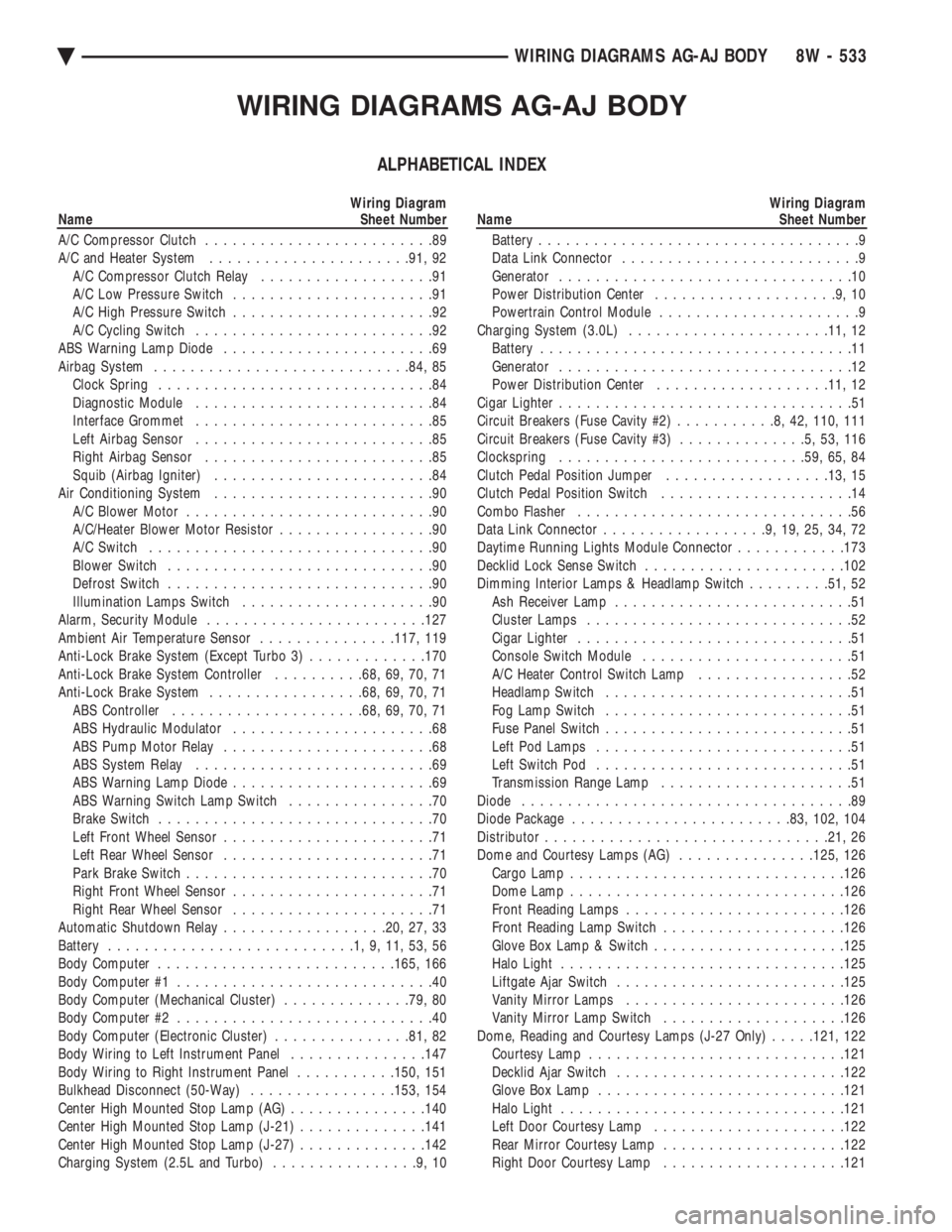
WIRING DIAGRAMS AG-AJ BODY
ALPHABETICAL INDEX
Wiring Diagram
Name Sheet Number
A/C Compressor Clutch .........................89
A/C and Heater System ..................... .91, 92
A/C Compressor Clutch Relay ...................91
A/C Low Pressure Switch ......................91
A/C High Pressure Switch ......................92
A/C Cycling Switch ..........................92
ABS Warning Lamp Diode .......................69
Airbag System ........................... .84, 85
Clock Spring ..............................84
Diagnostic Module ..........................84
Interface Grommet ..........................85
Left Airbag Sensor ..........................85
Right Airbag Sensor .........................85
Squib (Airbag Igniter) ........................84
Air Conditioning System ........................90
A/C Blower Motor ...........................90
A/C/Heater Blower Motor Resistor .................90
A/C Switch ...............................90
Blower Switch .............................90
Defrost Switch .............................90
Illumination Lamps Switch .....................90
Alarm, Security Module ....................... .127
Ambient Air Temperature Sensor ...............117, 119
Anti-Lock Brake System (Except Turbo 3) .............170
Anti-Lock Brake System Controller ..........68, 69, 70, 71
Anti-Lock Brake System .................68, 69, 70, 71
ABS Controller .................... .68, 69, 70, 71
ABS Hydraulic Modulator ......................68
ABS Pump Motor Relay .......................68
ABS System Relay ..........................69
ABS Warning Lamp Diode ......................69
ABS Warning Switch Lamp Switch ................70
Brake Switch ..............................70
Left Front Wheel Sensor .......................71
Left Rear Wheel Sensor .......................71
Park Brake Switch ...........................70
Right Front Wheel Sensor ......................71
Right Rear Wheel Sensor ......................71
Automatic Shutdown Relay ..................20, 27, 33
Battery ...........................1,9,11,53,56
Body Computer ......................... .165, 166
Body Computer #1 ............................40
Body Computer (Mechanical Cluster) ..............79, 80
Body Computer #2 ............................40
Body Computer (Electronic Cluster) ...............81, 82
Body Wiring to Left Instrument Panel ...............147
Body Wiring to Right Instrument Panel ...........150, 151
Bulkhead Disconnect (50-Way) ................153, 154
Center High Mounted Stop Lamp (AG) ...............140
Center High Mounted Stop Lamp (J-21) ..............141
Center High Mounted Stop Lamp (J-27) ..............142
Charging System (2.5L and Turbo) ................9,10Wiring Diagram
Name Sheet Number
Battery ...................................9
Data Link Connector ..........................9
Generator ................................10
Power Distribution Center ....................9,10
Powertrain Control Module ......................9
Charging System (3.0L) ..................... .11, 12
Battery ..................................11
Generator ................................12
Power Distribution Center .................. .11, 12
Cigar Lighter ................................51
Circuit Breakers (Fuse Cavity #2) ...........8,42,110, 111
Circuit Breakers (Fuse Cavity #3) ..............5,53,116
Clockspring .......................... .59, 65, 84
Clutch Pedal Position Jumper ..................13, 15
Clutch Pedal Position Switch .....................14
Combo Flasher ..............................56
Data Link Connector ..................9,19,25,34,72
Daytime Running Lights Module Connector ............173
Decklid Lock Sense Switch ..................... .102
Dimming Interior Lamps & Headlamp Switch .........51, 52
Ash Receiver Lamp ..........................51
Cluster Lamps .............................52
Cigar Lighter ..............................51
Console Switch Module .......................51
A/C Heater Control Switch Lamp .................52
Headlamp Switch ...........................51
Fog Lamp Switch ...........................51
Fuse Panel Switch ...........................51
Left Pod Lamps ............................51
Left Switch Pod ............................51
Transmission Range Lamp .....................51
Diode ....................................89
Diode Package ....................... .83, 102, 104
Distributor .............................. .21, 26
Dome and Courtesy Lamps (AG) ...............125, 126
Cargo Lamp ............................. .126
Dome Lamp ............................. .126
Front Reading Lamps ....................... .126
Front Reading Lamp Switch ................... .126
Glove Box Lamp & Switch .................... .125
Halo Light .............................. .125
Liftgate Ajar Switch ........................ .125
Vanity Mirror Lamps ....................... .126
Vanity Mirror Lamp Switch ................... .126
Dome, Reading and Courtesy Lamps (J-27 Only) .....121, 122
Courtesy Lamp ........................... .121
Decklid Ajar Switch ........................ .122
Glove Box Lamp .......................... .121
Halo Light .............................. .121
Left Door Courtesy Lamp .................... .122
Rear Mirror Courtesy Lamp ................... .122
Right Door Courtesy Lamp ................... .121
Ä WIRING DIAGRAMS AG-AJ BODY 8W - 533