1993 CHEVROLET PLYMOUTH ACCLAIM ECU
[x] Cancel search: ECUPage 531 of 2438

(3) Remove switch assembly and escutcheon from
switch module by removing four attaching screws
(Fig. 37).
(4) Remove headlamp switch mounting plate from
switch by removing retaining nut. (5) For installation reverse above procedures.
REAR WINDOW DEFOGGER SWITCHREPLACEMENT
(1) Remove headlamp and accessory switch module
from instrument panel (Fig. 36). (2) Remove rear window defogger switch by de-
pressing snap-in clips on top and bottom of switch. (3) For installation reverse above procedures.
HOOD RELEASE HANDLE AND CABLEREPLACEMENT
(1) Disconnect hood release cable at hood latch.
(2) Remove two screws from underside of hood re-
lease handle. (3) Pull mechanism assembly rearward to remove.
(4) For installation reverse above procedures.
PARK BRAKE RELEASE HANDLE AND LINK REPLACEMENT
(1) Remove left side under panel silencer.
(2) Remove park brake link from lever on park
brake mechanism. (3) Remove upper and lower cluster bezels.
(4) Pull park brake release handle and remove
screw. (5) Remove column cover/park brake release han-
dle assembly by removing four remaining screws. (6) For installation reverse above procedures.
LAMP OUTAGE MODULE REPLACEMENT
(1) Disconnect battery negative cable and isolate
or remove fuse #13 prior to removing switch or wires
may short to ground. (2) Remove lower right instrument panel silencer.
(3) Remove glove box and ash receiver module.
(4) Remove three screws attaching the mounting
bracket to instrument panel. (5) Lower bracket and module assembly, to discon-
nect wire connectors. (6) Remove two screws attaching the Lamp Outage
Module to bracket. (7) Remove two screws attaching the security mod-
ule to bracket. (8) To installation reverse above procedures.
BODY CONTROLLER REPLACEMENT
(1) Remove right side door sill and kick panel trim
five screws (Fig. 38).
(2) Disconnect body controller wiring.
(3) Remove controller retaining nuts.
(4) For installation reverse above procedures.
GLOVE BOX/ASH RECEIVER ASSEMBLY REPLACEMENT
(1) Disconnect battery negative cable and isolate
or remove fuse #13 prior to removing switch or wires
may short to ground. (2) Remove center support cover/floor console as
necessary. (3) Disconnect glovebox/Ash receiver wiring con-
nectors (Fig. 39). (4) Remove ten screws around edge of glovebox/ash
receiver assembly. (5) Remove glovebox/ash receiver module from in-
strument panel. (6) For installation reverse above procedures.
Fig. 37 Headlamp and Accessory Switch
Fig. 38 Body Controller Location
Ä INSTRUMENT PANEL AND GAUGES 8E - 39
Page 533 of 2438
(4) Remove panel top cover by pushing forward
and prying up, using a straight edge to assist in the
removal. (5) Disconnect bulkhead connector at brace under
instrument panel at left side. (6) Remove glovebox/ash receiver module and right
instrument panel silencer. (7) Remove center panel support brace and air bag
diagnostic module assembly. (8) Disconnect wiring to airbag module.
(9) Remove upper and lower cluster bezels.
(10) Remove steering column cover.
(11) Remove steering column mounting nuts and
lower steering column. (12) Unhook shift indicator cable eyelet from steer-
ing column actuator. (13) Unlatch lock tab in shift indicator column in-
sert and squeeze legs together to remove from steer-
ing column. (14) Remove cluster assembly while guiding trans-
mission range indicator guide tube through access
hole in the base panel. (15) Remove instrument panel steering column
opening support/hood release handle assembly. (16) Remove two steering column upper studs and
loosen side cowl tie-down bolts. (17) Remove steering column tilt lever.
(18) Remove upper and lower lock housing shroud.
(19) Remove lower fixed shroud.
(20) Remove upper fixed shroud (snaps in place).
(21) Disconnect airbag pigtail, ignition switch and
halo light/key buzzer switch wiring. (22) Disconnect Multi-function switch by loosening
connector jack screw and pulling connector from
switch. (23) Disconnect airbag pigtail from wiring trough
housing by pulling two push fasteners. (24) Remove wiring trough from steering column.
(25) Remove defroster ducts.
(26) Remove five screws along fence line and roll
panel down, attach a hook to hold in position. (27) Open hood and remove plenum grill.
(28) Disconnect washer bottle, resistor block and
under hood lamp wiring. Washer bottle must be re-
moved to gain access. (29) Remove grommet and pull plenum wiring into
vehicle through plenum panel. (30) Disconnect right demister hose from instru-
ment panel. (31) Disconnect antenna cable.
(32) Disconnect right and left 25 way body wiring
connectors. (33) Disconnect A/C heater control cables, wiring
connectors and vacuum harness. (34) Remove right side panel ground wire.
(35) Disconnect body controller wiring.
(36) Remove instrument panel assembly from vehi-
cle. (37) For installation reverse above procedures.
INTERIOR LAMP REPLACEMENT
The reading, overhead console and door lamps op-
erate when the doors are open or headlamp switch is
placed in courtesy position. Front overhead lamps re-
fer to Group 8C, Overhead Console.
TRUNK LAMP
The lamp has easily accessible without removing
components.
DOOR LAMP
Pry along the forward edge of the lens and pivot
lens out of the door trim panel. Remove lamp. To re-
move lamp housing, remove door trim panel. Refer to
Group 23, Body. Disconnect all wiring. Remove
screws, if so equipped securing lamp housing to trim
panel, and replace housing.
CÐPILLAR READING/COURTESY LAMP
Pry along the rearward edge of the lamp and pivot
lamp out from quarter trim panel. Disconnect wiring
and remove lamp cover. Replace lamp. The lamp operates when the doors are open or the
headlamp switch is turned to the courtesy mode. The
lamp will function as a reading lamp when the doors
are closed and the button switch on the lamp is de-
pressed.
ROOF RAIL READING
Pry along the bottom edge of the lens and pivot
lens out. Replace lamp. To remove the lamp, remove
the screw which retains the coat hook. Remove the
garnish molding. Disconnect the wiring harness. Re-
move the two clips which retain the lamp to the
molding. Replace lamp. The lamp operates like the
C-pillar reading/courtesy lamp.
Ä INSTRUMENT PANEL AND GAUGES 8E - 41
Page 542 of 2438

VEHICLE SPEED SENSOR TEST
For testing of the vehicle speed sensor and related
components using DRB II, refer to the appropriate
Powertrain Diagnostics Test Procedure Manual.
TACHOMETER DRIVE MODULE REMOVAL
(1) Remove cluster assembly.
(2) Pull tachometer drive module from printed cir-
cuit board (Fig. 22). (3) For installation reverse above procedures. Use
care when aligning module to printed circuit board.
PRINTED CIRCUIT BOARD REMOVAL
(1) Remove cluster assembly.
(2) Remove mounting screws securing printed cir-
cuit board to cluster housing. (3) Remove tachometer drive module (Fig. 22).
(4) Twist out all lamp sockets.
(5) For installation reverse above procedures.
CLUSTER LAMPS REMOVALÐMECHANIALCLUSTER ONLY
(1) Remove cluster assembly (Fig. 23).
(2) Remove one piece integral lamp and socket
from rear of cluster.
ELECTRONIC CLUSTER
Refer to Body Diagnostic Procedures Manual when
using DRB II.
SELF DIAGNOSTIC SYSTEM
The electronic clusters have an internal diagnostic
routing to isolate problems within the cluster.
Fig. 20 Vehicle Speed Sensor and Speedometer Pinion
Fig. 21 Vehicle Speed Sensor Removal
Fig. 22 Cluster Printed Circuit Board
Fig. 19 Vehicle Speed Sensor and Connector
8E - 50 INSTRUMENT PANEL AND GAUGES Ä
Page 548 of 2438
(7) Unscrew lighter receptacle shell from element
and remove. (8) For installation reverse above procedures.
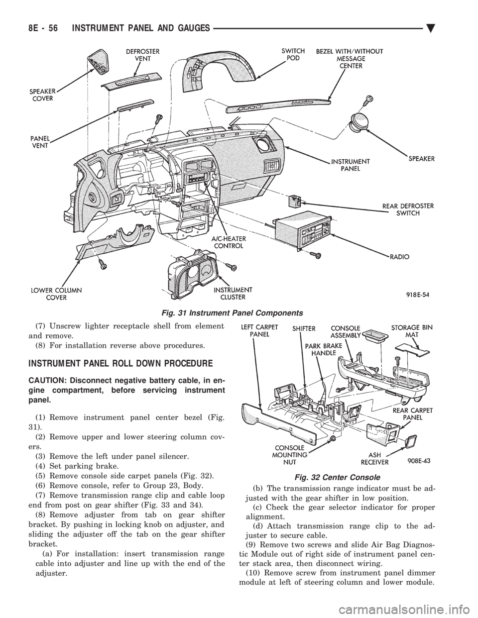
INSTRUMENT PANEL ROLL DOWN PROCEDURE
CAUTION: Disconnect negative battery cable, in en-
gine compartment, before servicing instrument
panel.
(1) Remove instrument panel center bezel (Fig.
31). (2) Remove upper and lower steering column cov-
ers. (3) Remove the left under panel silencer.
(4) Set parking brake.
(5) Remove console side carpet panels (Fig. 32).
(6) Remove console, refer to Group 23, Body.
(7) Remove transmission range clip and cable loop
end from post on gear shifter (Fig. 33 and 34). (8) Remove adjuster from tab on gear shifter
bracket. By pushing in locking knob on adjuster, and
sliding the adjuster off the tab on the gear shifter
bracket. (a) For installation: insert transmission range
cable into adjuster and line up with the end of the
adjuster. (b) The transmission range indicator must be ad-
justed with the gear shifter in low position. (c) Check the gear selector indicator for proper
alignment. (d) Attach transmission range clip to the ad-
juster to secure cable.
(9) Remove two screws and slide Air Bag Diagnos-
tic Module out of right side of instrument panel cen-
ter stack area, then disconnect wiring. (10) Remove screw from instrument panel dimmer
module at left of steering column and lower module.
Fig. 31 Instrument Panel Components
Fig. 32 Center Console
8E - 56 INSTRUMENT PANEL AND GAUGES Ä
Page 552 of 2438

CLUSTER BEZEL REPLACEMENT
(1) Remove four screws holding bezel to instru-
ment panel (Fig. 7). (2) Remove bezel over steering wheel. (3) For installation reverse above procedures.
CLUSTER MASK AND LENS
REMOVAL
(1) Remove instrument cluster bezel.
(2) Remove five screws holding mask and lens to
cluster. (3) Remove mask and lens.
(4) For installation reverse above procedures.
CLUSTER ASSEMBLY REPLACEMENT
(1) Disconnect battery to assure no Air Bag Sys-
tem fault codes are stored. (2) Remove cluster bezel (Fig. 7).
(3) Remove the upper steering column cover.
(4) Remove the four screws attaching cluster hous-
ing to the base panel. (5) Pull cluster rearward, reach behind cluster and
disconnect the two wiring harnesses. (6) Remove cluster assembly.
INSTALLATION (1) Connect wiring harnesses.
(2) Position cluster and secure to base panel with
four screws. (3) Install upper and lower steering column cover.
(4) Install cluster bezel.
Fig. 5 Brake System Warning Lamp Diagnosis
Fig. 6 Brake Warning Lamp Switch
8E - 60 INSTRUMENT PANEL AND GAUGES Ä
Page 556 of 2438
(4) Remove two retaining screws and pull fuel
gauge straight back. (5) For installation reverse above procedures.
TEMPERATURE GAUGE REPLACEMENT
(1) Remove instrument cluster bezel (Fig. 7).
(2) Remove mask and lens.
(3) Remove two retaining screws and pull temper-
ature gauge straight back. (4) For installation reverse above procedures.
VOLTMETER REPLACEMENT
(1) Remove instrument cluster bezel (Fig. 7).
(2) Remove mask and lens.
(3) Remove three speedometer retaining screws
and pull the speedometer straight back and set aside. (4) Remove two voltmeter retaining screws and
pull voltmeter straight back. (5) For installation, place voltmeter on gauge pins
and push until gauge is securely seated in cluster
and reverse above procedures.
TACHOMETER REPLACEMENT
(1) Remove instrument cluster bezel.
(2) Remove mask and lens.
(3) Remove three retaining screws and pull ta-
chometer straight back. (4) For installation, place tachometer on gauge
pins and push until gauge is securely seated in clus- ter and reverse above procedures.
TACHOMETER CIRCUIT TESTING
(1) Remove cluster.
(2) Check for battery voltage at cavity J if instru-
ment cluster gray connector. (3) With the ignition in the ON position, check for
battery voltage at cavity K of the instrument cluster
gray connector (Fig. 8). (4) Check cavity F of the instrument cluster red
connector for continuity to ground (Fig. 8). (5) Check for tachometer signal from the power-
train control module by connecting an AC DIGITAL
VOLTMETER to cavity H of the instrument cluster
gray connector and ground. A reading of at least 1.0
volts should be present with the engine running. (a) If voltage is within specification, go to step 7.
(b) If voltage is NOT within specification, per-
form steps 5 and 6.
(6) If there is less than 1.0 volts at cavity H check
for continuity between cavity H of the instrument
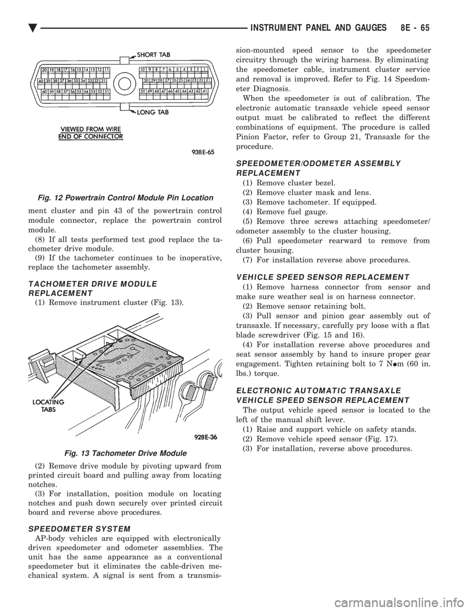
cluster and pin 43 of the powertrain control module
connector (Fig. 12). Also, check the connector at the
powertrain control module for damaged pins or ter-
minal push outs. (7) If voltage is less than 1.0 volts at cavity H and
there is continuity between cavity H of the instru-
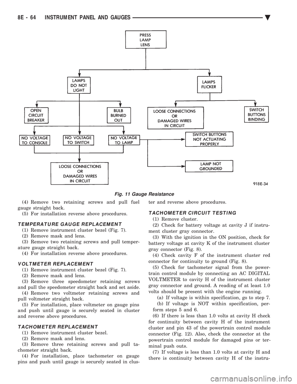
Fig. 11 Gauge Resistance
8E - 64 INSTRUMENT PANEL AND GAUGES Ä
Page 557 of 2438
ment cluster and pin 43 of the powertrain control
module connector, replace the powertrain control
module. (8) If all tests performed test good replace the ta-
chometer drive module. (9) If the tachometer continues to be inoperative,
replace the tachometer assembly.
TACHOMETER DRIVE MODULE REPLACEMENT
(1) Remove instrument cluster (Fig. 13).
(2) Remove drive module by pivoting upward from
printed circuit board and pulling away from locating
notches. (3) For installation, position module on locating
notches and push down securely over printed circuit
board and reverse above procedures.
SPEEDOMETER SYSTEM
AP-body vehicles are equipped with electronically
driven speedometer and odometer assemblies. The
unit has the same appearance as a conventional
speedometer but it eliminates the cable-driven me-
chanical system. A signal is sent from a transmis- sion-mounted speed sensor to the speedometer
circuitry through the wiring harness. By eliminating
the speedometer cable, instrument cluster service
and removal is improved. Refer to Fig. 14 Speedom-
eter Diagnosis.
When the speedometer is out of calibration. The
electronic automatic transaxle vehicle speed sensor
output must be calibrated to reflect the different
combinations of equipment. The procedure is called
Pinion Factor, refer to Group 21, Transaxle for the
procedure.
SPEEDOMETER/ODOMETER ASSEMBLY REPLACEMENT
(1) Remove cluster bezel.
(2) Remove cluster mask and lens.
(3) Remove tachometer. If equipped.
(4) Remove fuel gauge.
(5) Remove three screws attaching speedometer/
odometer assembly to the cluster housing. (6) Pull speedometer rearward to remove from
cluster housing. (7) For installation reverse above procedures.
VEHICLE SPEED SENSOR REPLACEMENT
(1) Remove harness connector from sensor and
make sure weather seal is on harness connector. (2) Remove sensor retaining bolt.
(3) Pull sensor and pinion gear assembly out of
transaxle. If necessary, carefully pry loose with a flat
blade screwdriver (Fig. 15 and 16). (4) For installation reverse above procedures and
seat sensor assembly by hand to insure proper gear
engagement. Tighten retaining bolt to 7 N Im (60 in.
lbs.) torque.
ELECTRONIC AUTOMATIC TRANSAXLE VEHICLE SPEED SENSOR REPLACEMENT
The output vehicle speed sensor is located to the
left of the manual shift lever. (1) Raise and support vehicle on safety stands.
(2) Remove vehicle speed sensor (Fig. 17).
(3) For installation, reverse above procedures.
Fig. 12 Powertrain Control Module Pin Location
Fig. 13 Tachometer Drive Module
Ä INSTRUMENT PANEL AND GAUGES 8E - 65
Page 560 of 2438
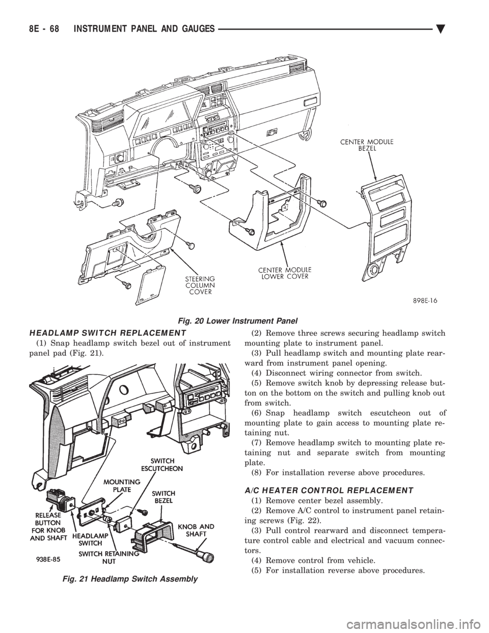
HEADLAMP SWITCH REPLACEMENT
(1) Snap headlamp switch bezel out of instrument
panel pad (Fig. 21). (2) Remove three screws securing headlamp switch
mounting plate to instrument panel. (3) Pull headlamp switch and mounting plate rear-
ward from instrument panel opening. (4) Disconnect wiring connector from switch.
(5) Remove switch knob by depressing release but-
ton on the bottom on the switch and pulling knob out
from switch. (6) Snap headlamp switch escutcheon out of
mounting plate to gain access to mounting plate re-
taining nut. (7) Remove headlamp switch to mounting plate re-
taining nut and separate switch from mounting
plate. (8) For installation reverse above procedures.
A/C HEATER CONTROL REPLACEMENT
(1) Remove center bezel assembly.
(2) Remove A/C control to instrument panel retain-
ing screws (Fig. 22). (3) Pull control rearward and disconnect tempera-
ture control cable and electrical and vacuum connec-
tors. (4) Remove control from vehicle.
(5) For installation reverse above procedures.
Fig. 20 Lower Instrument Panel
Fig. 21 Headlamp Switch Assembly
8E - 68 INSTRUMENT PANEL AND GAUGES Ä