1993 CHEVROLET PLYMOUTH ACCLAIM ECU
[x] Cancel search: ECUPage 457 of 2438

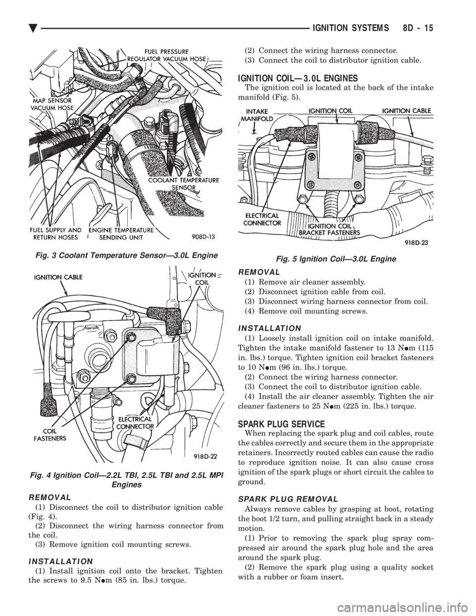
REMOVAL
(1) Disconnect the coil to distributor ignition cable
(Fig. 4). (2) Disconnect the wiring harness connector from
the coil. (3) Remove ignition coil mounting screws.
INSTALLATION
(1) Install ignition coil onto the bracket. Tighten
the screws to 9.5 N Im (85 in. lbs.) torque. (2) Connect the wiring harness connector.
(3) Connect the coil to distributor ignition cable.
IGNITION COILÐ3.0L ENGINES
The ignition coil is located at the back of the intake
manifold (Fig. 5).
REMOVAL
(1) Remove air cleaner assembly.
(2) Disconnect ignition cable from coil.
(3) Disconnect wiring harness connector from coil.
(4) Remove coil mounting screws.
INSTALLATION
(1) Loosely install ignition coil on intake manifold.
Tighten the intake manifold fastener to 13 N Im(115
in. lbs.) torque. Tighten ignition coil bracket fasteners
to 10 N Im (96 in. lbs.) torque.
(2) Connect the wiring harness connector.
(3) Connect the coil to distributor ignition cable.
(4) Install the air cleaner assembly. Tighten the air
cleaner fasteners to 25 N Im (225 in. lbs.) torque.
SPARK PLUG SERVICE
When replacing the spark plug and coil cables, route
the cables correctly and secure them in the appropriate
retainers. Incorrectly routed cables can cause the radio
to reproduce ignition noise. It can also cause cross
ignition of the spark plugs or short circuit the cables to
ground.
SPARK PLUG REMOVAL
Always remove cables by grasping at boot, rotating
the boot 1/2 turn, and pulling straight back in a steady
motion. (1) Prior to removing the spark plug spray com-
pressed air around the spark plug hole and the area
around the spark plug. (2) Remove the spark plug using a quality socket
with a rubber or foam insert.
Fig. 3 Coolant Temperature SensorÐ3.0L Engine
Fig. 4 Ignition CoilÐ2.2L TBI, 2.5L TBI and 2.5L MPI Engines
Fig. 5 Ignition CoilÐ3.0L Engine
Ä IGNITION SYSTEMS 8D - 15
Page 483 of 2438

(2) With engine running, move test probe along
entire length of all cables (approximately 0 to 1/8
inch gap). If punctures or cracks are present there
will be a noticeable spark jump from the faulty area
to the probe. Cracked, leaking or faulty cables should
be replaced. Use the following procedure when removing the
high tension cable from the spark plug. First, remove
the cable from the retaining bracket. Then grasp the
terminal as close as possible to the spark plug. Ro-
tate the cover (boot) slightly and pull straight back.
Do not use pliers and do not pull the cable at an
angle. Doing so will damage the insulation, cable
terminal or the spark plug insulator. Wipe spark
plug insulator clean before reinstalling cable
and cover. Resistance cables are identified by the words Elec-
tronic Suppression .
Use an ohmmeter to check cables for opens, loose
terminals or high resistance. (a) Remove cable from spark plug.
(b) Remove cable from the coil tower.
(c) Connect the ohmmeter between spark plug
end terminal and the coil end terminal. Resistance
should be within tolerance shown in the cable re-
sistance chart. If resistance is not within tolerance,
replace cable assembly. Test all spark plug cables
in same manner.
SPARK PLUG SERVICE
When replacing the spark plug cables, route the ca-
bles correctly and secure them in the appropriate re-
tainers. Incorrectly routed cables can cause the radio
to reproduce ignition noise. It can also cause cross ig-
nition of the spark plugs or short circuit the cables to
ground.
SPARK PLUG REMOVAL
Always remove cables by grasping at boot, rotating
the boot 1/2 turn, and pulling straight back in a
steady motion. (1) Prior to removing the spark plug spray com-
pressed air around the spark plug hole and the area
around the spark plug. (2) Remove the spark plug using a quality socket
with a rubber or foam insert. (3) Inspect the spark plug condition. Refer to
Spark Plug Condition in this section.
SPARK PLUG GAP ADJUSTMENT
Check the spark plug gap with a gap gauge. If the
gap is not correct, adjust it by bending the ground
electrode (Fig. 6).
SPARK PLUG INSTALLATION
(1) To avoid cross threading, start the spark plug
into the cylinder head by hand. (2) Tighten spark plugs to 28 N Im (20 ft. lbs.)
torque. (3) Install spark plug cables over spark plugs.
IDLE RPM TEST
WARNING: BE SURE TO APPLY PARKING BRAKE
AND/OR BLOCK WHEELS BEFORE PERFORMING
ANY ENGINE RUNNING TESTS.
Engine idle set rpmshould be tested and recorded
as it is when the vehicle is first brought into shop
for testing. This will assist in diagnosing complaints
of engine stalling, creeping and hard shifting on ve-
hicles equipped with automatic transaxle. Refer to the
Throttle Body Minimum Airflow procedures in Group
14.
IGNITION TIMING PROCEDURE
Ignition timing cannot be changed or set on Turbo
III, 3.3L or 3.8L engines. For diagnostic information,
refer to the DRBII scan tool and the appropriate
Powertrain Diagnostics Procedures manual.
CABLE RESISTANCE CHART
Fig. 6 Setting Spark Plug GapÐTypical
Ä IGNITION SYSTEMS 8D - 41
Page 498 of 2438

(b) Place gear shift lever in neutral or park.
(c) Remove guide tube from behind fuse block
and disconnect cable eyelet from column actuating
arm. (d) Release lock bar on column insert, squeeze
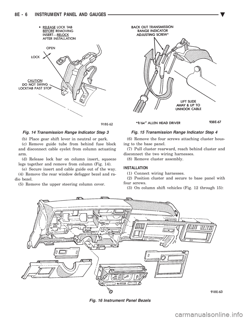
legs together and remove from column (Fig. 14). (e) Secure insert and cable guide out of the way.
(4) Remove the rear window defogger bezel and ra-
dio bezel. (5) Remove the upper steering column cover. (6) Remove the four screws attaching cluster hous-
ing to the base panel. (7) Pull cluster rearward, reach behind cluster and
disconnect the two wiring harnesses. (8) Remove cluster assembly.
INSTALLATION (1) Connect wiring harnesses.
(2) Position cluster and secure to base panel with
four screws. (3) On column shift vehicles (Fig. 12 through 15):
Fig. 15 Transmission Range Indicator Step 4
Fig. 16 Instrument Panel Bezels
Fig. 14 Transmission Range Indicator Step 3
8E - 6 INSTRUMENT PANEL AND GAUGES Ä
Page 499 of 2438

(a) Route transmission range indicator guide as-
sembly under left steering column wing and down
left side of column (Fig. 12). (b) Insert flange of column insert into column,
squeeze legs together with tabs under column
jacket and engage lock bar to secure insert (Fig.
14). (c) Hook cable eyelet to steering column actuator
check pointer, should indicate neutral. Do not kink
or bind transmission range indicator guide tube
and position guide tube in original location. (d) Adjust with tool if necessary to center pointer
on N (Neutral) and check in other gears (Fig. 15).
(4) Install upper and lower steering column cover.
(5) Install the rear window defogger bezel and ra-
dio bezel. (6) Install cluster bezel.
(7) Reconnect battery.
REMOVALÐCLUSTER WITHOUT TRANSMISSION RANGE
INDICATOR FROM STEERING COLUMN (1) Remove cluster bezel (Fig. 10).
(2) Remove four screws attaching cluster to base
panel. (3) Pull cluster rearward carefully, reach behind
and disconnect the two harness connectors. (4) Carefully rotate cluster and remove the two
transmission range indicator screws. (5) Remove cluster assembly.
(6) For installation reverse above procedures. (a) Do not kink guide tube when installing clus-
ter. (b) Replace guide tube behind fuse block.
GAUGES
It is not necessary to remove instrument clus-
ter assembly from vehicle for gauge replace-
ment. When removing gauge assemblies from cluster,
gauge must be pulled straight out, not twisted, or
damage to gauge pin may result.
MULTIPLE GAUGE MALFUNCTION
If the fuel, voltage and tachometer gauges appear
to be malfunctioning, remove the cluster assembly.
Check for good pin contact between the wire harness
and printed circuit board. If there is good contact,
check for ignition voltage at ignition cavity C of the
black connector. If there is ignition voltage, check for
continuity between the wire harness ground cavity H
of the black connector and ground. If there is conti-
nuity, replace printed circuit board. If the temperature, oil pressure and speedometer
gauges appear to be malfunctioning remove the clus-
ter assembly. Check for a good contact between the
wire harness and the printed circuit board. If there is
good contact, check for ignition voltage at cavity J of
the red connector. If there is voltage, check for con- tinuity at cavity H of the black connector. If there is
continuity, replace the printed circuit board.
If the temperature, fuel, voltage and speedometer
gauges appear to be malfunctioning, remove the clus-
ter assembly. Check for good pin contact between the
wire harness and the printed circuit board. If there is
good contact, check ignition voltage at cavity J of the
red connector. If there is voltage, check for continuity
at cavity H of the black connector. If there is conti-
nuity, replace the printed circuit board.
GAUGE INOPERATIVE (FIG. 17 THROUGH 23)
(1) Remove gauge in question.
Fig. 17 Fuel Gauge PinsÐWith Tachometer
Fig. 18 Fuel Gauge PinsÐWithout Tachometer
Ä INSTRUMENT PANEL AND GAUGES 8E - 7
Page 505 of 2438

(3) Remove lamp sockets as necessary by turning
them counterclockwise (Fig. 34 and 35).
PRINTED CIRCUIT BOARD REPLACEMENT
(1) Remove cluster assembly.
(2) Remove tachometer drive module, low fuel re-
lay and gauge alert module (Fig. 32). (3) Remove all cluster lamps.
(4) Remove mounting screws securing printed cir-
cuit board to cluster housing (Fig. 34). (5) For installation reverse above procedures.
ELECTRONIC CLUSTER
SELF DIAGNOSTIC SYSTEM
The electronic clusters (Fig. 36) have an internal
diagnostics routing to isolate problems within the
cluster or sending units. Using the cluster Self-Diagnostic Test will deter-
mine whether problem is within cluster or outside of
cluster (Fig. 37 and 38). Successful completion of the SELF DIAGNOSTIC
TEST indicates that the problem is in the connectors
or sensors outside of the module. Refer to Fig. 39 for
terminal listing.
CONDITION: CLUSTER DISPLAYS DO NOT ILLUMINATE AFTER VEHICLE IS STARTED
PROCEDURE
(1) Check fuses and verify battery and ignition
voltage at cluster connector. (2) Check ground from cluster connector to instru-
ment panel ground stud. (3) Check lamps, replace if necessary.
Fig. 34 Mechanical Cluster Lamp Location
Fig. 33 Gauge Alert Module
Ä INSTRUMENT PANEL AND GAUGES 8E - 13
Page 507 of 2438

CONDITION: SPEEDOMETER AND ODOMETER ARE INOPERATIVE OR OPERATESINTERMITTENTLY
PROCEDURE
Check for defective vehicle speed sensor wiring.
CONDITION: OIL GAUGE, FUEL GAUGE, TEMPERATURE GAUGE, OR VOLTAGE GAUGEINOPERATIVE
PROCEDURE
Check for defective sending unit or wiring: (a) Sending units and wiring can be checked by
grounding the connector leads, at the sending unit,
in the vehicle. (b) With the ignition in the ON position, a
grounded input will cause the oil, fuel, or temper-
ature gauge to read maximum.
CONDITION: CLUSTER DISPLAY DOES NOT DIM WHEN HEADLAMP SWITCH ISACTIVATED AND RHEOSTAT ROTATED
PROCEDURE
(1) Check fuses in headlamp circuit.
(2) Check for loose connections or defective wiring
from headlamp switch to the cluster. (3) Check for defective headlamp switch.
(4) The electronic instrument cluster requires both
a marker feed and illumination feed to operate cor-
rectly.
SWITCH AND PANEL COMPONENT SERVICE
HEADLAMP/FOG LAMP SWITCH REPLACEMENT
(1) Remove cluster bezel (Fig. 40).
(2) Remove three screws securing headlamp switch
mounting plate to base panel (Fig. 41). (3) Pull headlamp/fog lamp switch mounting plate
rearward. Disconnect wiring connectors from head-
lamp switch and fog lamp switch pigtail (Fig. 42). (4) Remove knob and stem by depressing button on
bottom of the switch (Fig. 43). (5) Snap-out escutcheon.
(6) Remove fog lamp switch from escutcheon.
(7) Remove nut that attaches headlamp switch to
mounting plate (Fig. 44). (8) For installation reverse above procedures.
FOG LAMP SWITCH TEST
(1) Remove the fog lamp switch from mounting lo-
cation. (2) Disconnect the wiring harness from the switch
pigtail. (3) Using a Ohmmeter, test for continuity between
the terminals of the switch pigtail (Fig. 45). (4) If not OK, replace switch.
LOWER STEERING COLUMN COVERREPLACEMENT
(1) Disconnect park brake release rod from park
brake. (2) Remove fuse box access door and remove screw
from lower column cover (Fig. 46). (3) Remove screws from lower cover, four across
the top and two on bottom. (4) Remove lower steering column cover.
(5) For installation reverse above procedures.
LEFT LOWER INSTRUMENT PANEL SILENCER REPLACEMENT
(1) Remove screws from front of silencer (Fig. 47).
(2) Remove push nut.
(3) Remove silencer.
(4) For installation reverse above procedures.
RIGHT LOWER INSTRUMENT PANEL SILENCER REPLACEMENT
(1) On floor shift vehicles, remove console assem-
bly and center brace bracket. (2) On column shift vehicles, remove center brace
bracket. (3) Remove screws from front of silencer (Fig. 47).
(4) Remove three push nuts from rear of silencer.
(5) Remove lower right silencer.
(6) For installation reverse above procedures.
GLOVE BOX ASSEMBLY REPLACEMENT
(1) Disconnect battery negative cable and isolate
or remove fuse #2 prior to removing switch or wires
may short to ground. (2) Open glove box door and disconnect check
strap. (3) Remove glove box light and switch by squeez-
ing retaining tabs from behind switch mount and
slide rearward. Disconnect wiring connectors. (4) Remove 11 screws from glove box assembly
(Fig. 48). (5) Remove glove box assembly.
Fig. 36 Electronic Cluster
Ä INSTRUMENT PANEL AND GAUGES 8E - 15
Page 519 of 2438

(3) Remove lower steering column cover (Fig. 10
through 14).
(4) Place gear shift lever in neutral or park.
(5) Remove guide tube from behind fuse block and
disconnect cable eyelet from column actuating arm. (6) Release lock bar on column insert, squeeze legs
together and remove from column (Fig. 13). (7) Secure insert and cable guide out of the way.
(8) Remove the rear window defogger bezel and ra-
dio bezel. (9) Remove the upper steering column cover.
(10) Remove the four screws attaching cluster
housing to the base panel (Fig. 15). (11) Pull cluster rearward, reach behind cluster
and disconnect the two wiring harnesses. (12) Remove cluster assembly. INSTALLATION
(1) Connect wiring harnesses.
(2) Install cluster assembly while routing trans-
mission range indicator guide tube through access
hole in base panel (Fig. 10 through 14). Release
guide tube from behind fuse block. (3) Insert flange of column insert into column,
squeeze legs together with tabs under column jacket
and engage lock bar to secure insert (Fig. 13). (4) Hook cable eyelet to steering column actuator
check pointer, should indicate neutral. Do not kink
Fig. 10 Transmission Range Indicator
Fig. 11 Transmission Range Indicator Step 1
Fig. 12 Transmission Range Indicator Step 2
Fig. 13 Transmission Range Indicator Step 3
Ä INSTRUMENT PANEL AND GAUGES 8E - 27
Page 524 of 2438

(5) For installation reverse above procedures. Seat
sensor assembly by hand to insure proper gear en-
gagement. Tighten retaining bolt to 7 N Im (60 in.
lbs.) torque.
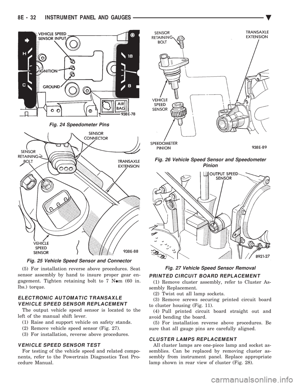
ELECTRONIC AUTOMATIC TRANSAXLE VEHICLE SPEED SENSOR REPLACEMENT
The output vehicle speed sensor is located to the
left of the manual shift lever. (1) Raise and support vehicle on safety stands.
(2) Remove vehicle speed sensor (Fig. 27).
(3) For installation, reverse above procedures.
VEHICLE SPEED SENSOR TEST
For testing of the vehicle speed and related compo-
nents, refer to the Powertrain Diagnostics Test Pro-
cedure Manual.
PRINTED CIRCUIT BOARD REPLACEMENT
(1) Remove cluster assembly, refer to Cluster As-
sembly Replacement. (2) Twist out all lamp sockets.
(3) Remove screws securing printed circuit board
to cluster housing (Fig. 11). (4) Pull printed circuit board straight out and
avoid bending the board. (5) For installation reverse above procedures. Be
sure that all gauge pins are carefully aligned.
CLUSTER LAMPS REPLACEMENT
All cluster lamps are one-piece lamp and socket as-
semblies. Can be replaced by removing cluster as-
sembly from instrument panel. Replace appropriate
lamp shown in rear view of cluster (Fig. 28).
Fig. 24 Speedometer Pins
Fig. 25 Vehicle Speed Sensor and Connector
Fig. 26 Vehicle Speed Sensor and Speedometer Pinion
Fig. 27 Vehicle Speed Sensor Removal
8E - 32 INSTRUMENT PANEL AND GAUGES Ä