Page 1809 of 2438
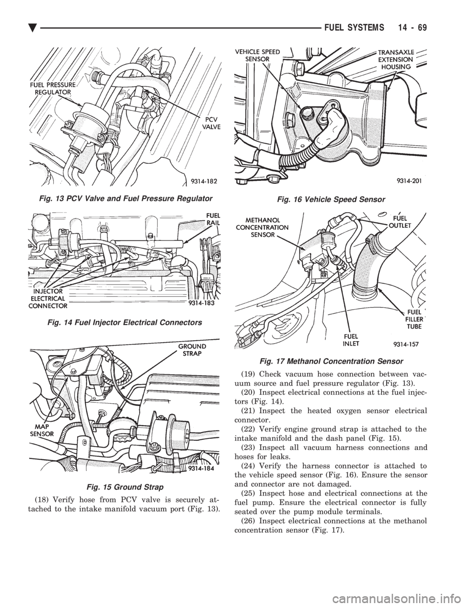
(18) Verify hose from PCV valve is securely at-
tached to the intake manifold vacuum port (Fig. 13). (19) Check vacuum hose connection between vac-
uum source and fuel pressure regulator (Fig. 13). (20) Inspect electrical connections at the fuel injec-
tors (Fig. 14). (21) Inspect the heated oxygen sensor electrical
connector. (22) Verify engine ground strap is attached to the
intake manifold and the dash panel (Fig. 15). (23) Inspect all vacuum harness connections and
hoses for leaks. (24) Verify the harness connector is attached to
the vehicle speed sensor (Fig. 16). Ensure the sensor
and connector are not damaged. (25) Inspect hose and electrical connections at the
fuel pump. Ensure the electrical connector is fully
seated over the pump module terminals. (26) Inspect electrical connections at the methanol
concentration sensor (Fig. 17).
Fig. 13 PCV Valve and Fuel Pressure Regulator
Fig. 14 Fuel Injector Electrical Connectors
Fig. 15 Ground Strap
Fig. 16 Vehicle Speed Sensor
Fig. 17 Methanol Concentration Sensor
Ä FUEL SYSTEMS 14 - 69
Page 1836 of 2438
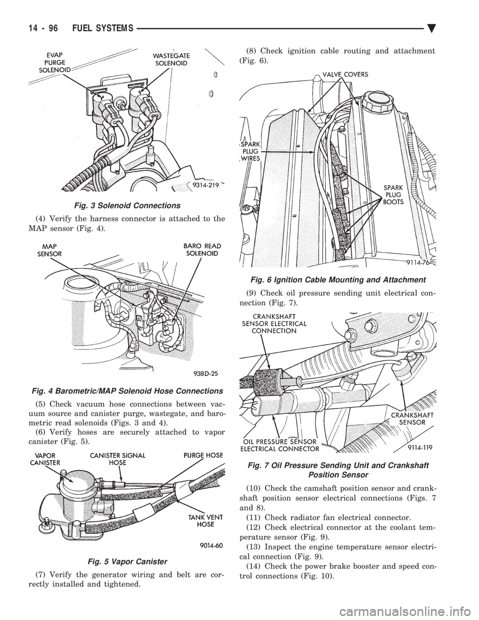
(4) Verify the harness connector is attached to the
MAP sensor (Fig. 4).
(5) Check vacuum hose connections between vac-
uum source and canister purge, wastegate, and baro-
metric read solenoids (Figs. 3 and 4). (6) Verify hoses are securely attached to vapor
canister (Fig. 5).
(7) Verify the generator wiring and belt are cor-
rectly installed and tightened. (8) Check ignition cable routing and attachment
(Fig. 6).
(9) Check oil pressure sending unit electrical con-
nection (Fig. 7).
(10) Check the camshaft position sensor and crank-
shaft position sensor electrical connections (Figs. 7
and 8). (11) Check radiator fan electrical connector.
(12) Check electrical connector at the coolant tem-
perature sensor (Fig. 9). (13) Inspect the engine temperature sensor electri-
cal connection (Fig. 9). (14) Check the power brake booster and speed con-
trol connections (Fig. 10).
Fig. 6 Ignition Cable Mounting and Attachment
Fig. 7 Oil Pressure Sending Unit and Crankshaft Position Sensor
Fig. 3 Solenoid Connections
Fig. 4 Barometric/MAP Solenoid Hose Connections
Fig. 5 Vapor Canister
14 - 96 FUEL SYSTEMS Ä
Page 1837 of 2438
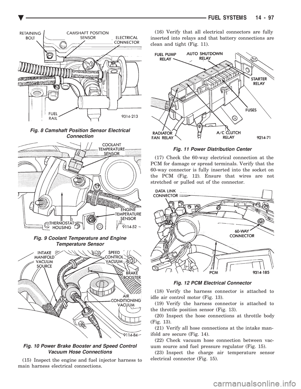
(15) Inspect the engine and fuel injector harness to
main harness electrical connections. (16) Verify that all electrical connectors are fully
inserted into relays and that battery connections are
clean and tight (Fig. 11).
(17) Check the 60-way electrical connection at the
PCM for damage or spread terminals. Verify that the
60-way connector is fully inserted into the socket on
the PCM (Fig. 12). Ensure that wires are not
stretched or pulled out of the connector.
(18) Verify the harness connector is attached to
idle air control motor (Fig. 13). (19) Verify the harness connector is attached to
the throttle position sensor (Fig. 13). (20) Inspect the hose connections at throttle body
(Fig. 13). (21) Verify all hose connections at the intake man-
ifold are secure (Fig. 14). (22) Check vacuum hose connection between vac-
uum source and fuel pressure regulator (Fig. 15). (23) Inspect the charge air temperature sensor
electrical connector (Fig. 15).
Fig. 8 Camshaft Position Sensor Electrical Connection
Fig. 9 Coolant Temperature and EngineTemperature Sensor
Fig. 10 Power Brake Booster and Speed Control Vacuum Hose Connections
Fig. 11 Power Distribution Center
Fig. 12 PCM Electrical Connector
Ä FUEL SYSTEMS 14 - 97
Page 1838 of 2438
(24) Inspect fuel injectors wiring connectors (Fig.
15). (25) Inspect the knock sensor electrical connector
(Fig. 16). (26) Inspect the heated oxygen sensor electrical con-
nector (Fig. 17). (27) Verify engine ground strap is attached to the
engine and the dash panel. (28) Verify the hose connections on the turbo charger
are secure (Fig. 18). (29) Check the turbocharger bypass valve hose con-
nections. (30) Verify 2-way connector is attached to vehicle
speed sensor (Fig. 19).
Fig. 13 Throttle Body Electrical and Vacuum Hose Connections
Fig. 14 Intake Manifold Vacuum Connections
Fig. 15 Vacuum and Electrical Connections
Fig. 16 Knock Sensor
Fig. 17 Heated Oxygen Sensor
14 - 98 FUEL SYSTEMS Ä
Page 1866 of 2438
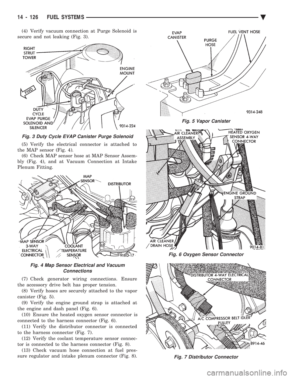
(4) Verify vacuum connection at Purge Solenoid is
secure and not leaking (Fig. 3).
(5) Verify the electrical connector is attached to
the MAP sensor (Fig. 4). (6) Check MAP sensor hose at MAP Sensor Assem-
bly (Fig. 4), and at Vacuum Connection at Intake
Plenum Fitting.
(7) Check generator wiring connections. Ensure
the accessory drive belt has proper tension. (8) Verify hoses are securely attached to the vapor
canister (Fig. 5). (9) Verify the engine ground strap is attached at
the engine and dash panel (Fig. 6). (10) Ensure the heated oxygen sensor connector is
connected to the harness connector (Fig. 6). (11) Verify the distributor connector is connected
to the harness connector (Fig. 7). (12) Verify the coolant temperature sensor connec-
tor is connected to the harness connector (Fig. 8). (13) Check vacuum hose connection at fuel pres-
sure regulator and intake plenum connector (Fig. 8).
Fig. 3 Duty Cycle EVAP Canister Purge Solenoid
Fig. 4 Map Sensor Electrical and Vacuum Connections
Fig. 5 Vapor Canister
Fig. 6 Oxygen Sensor Connector
Fig. 7 Distributor Connector
14 - 126 FUEL SYSTEMS Ä
Page 1867 of 2438
(14) Ensure the harness connector is securely at-
tached to each fuel injector. (15) Check the oil pressure sending unit electrical
connection (Fig. 9).
(16) Check hose connections at throttle body (Fig.
10). (17) Check throttle body electrical connections
(Fig. 10). (18) Check PCV hose connections (Fig. 11).
(19) If equipped, check EGR system vacuum hose
connections (Fig. 12). (20) If equipped, check EGR tube to intake plenum
connections (Fig. 12). (21) Inspect the electronic EGR transducer sole-
noid electrical connector. (22) Ensure the vacuum connections at the elec-
tronic EGR transducer is secure and not leaking.
Fig. 8 Coolant Temperature Sensor and Vacuum Connections
Fig. 9 Oil Pressure Sending Unit ElectricalConnection
Fig. 10 Throttle Body Electrical and Vacuum Hose Connections
Fig. 11 Positive Crankcase Ventilation (PCV) System
Fig. 12 EGR System Vacuum Hose Connections
Ä FUEL SYSTEMS 14 - 127
Page 1897 of 2438
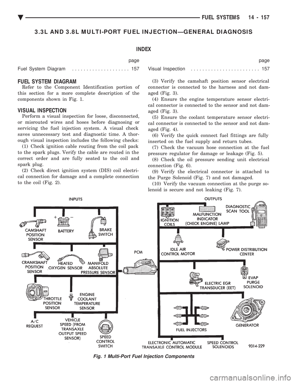
3.3L AND 3.8L MULTI-PORT FUEL INJECTIONÐGENERAL DIAGNOSIS INDEX
page page
Fuel System Diagram .................... 157 Visual Inspection........................ 157
FUEL SYSTEM DIAGRAM
Refer to the Component Identification portion of
this section for a more complete description of the
components shown in Fig. 1.
VISUAL INSPECTION
Perform a visual inspection for loose, disconnected,
or misrouted wires and hoses before diagnosing or
servicing the fuel injection system. A visual check
saves unnecessary test and diagnostic time. A thor-
ough visual inspection includes the following checks: (1) Check ignition cable routing from the coil pack
to the spark plugs. Verify the cable are routed in the
correct order and are fully seated to the coil and
spark plug. (2) Check direct ignition system (DIS) coil electri-
cal connection for damage and a complete connection
to the coil (Fig. 2). (3) Verify the camshaft position sensor electrical
connector is connected to the harness and not dam-
aged (Fig. 3). (4) Ensure the engine temperature sensor electri-
cal connector is connected to the sensor and not dam-
aged (Fig. 3). (5) Ensure the coolant temperature sensor electri-
cal connector is connected to the sensor and not dam-
aged (Fig. 4). (6) Verify the quick connect fuel fittings are fully
inserted on the fuel supply and return tubes. (7) Check the vacuum hose connection at the fuel
pressure regulator for damage or leakage (Fig. 5). (8) Check the oil pressure sending unit electrical
connection (Fig. 6). (9) Verify the electrical connector is attached to
the Purge Solenoid (Fig. 7) and not damaged. (10) Verify the vacuum connection at the purge so-
lenoid is secure and not leaking (Fig. 7).
Fig. 1 Multi-Port Fuel Injection Components
Ä FUEL SYSTEMS 14 - 157
Page 1898 of 2438
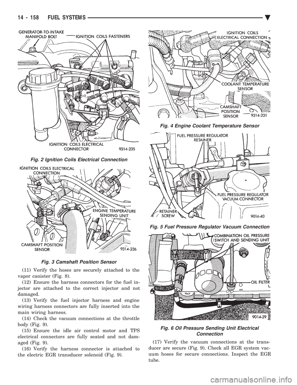
(11) Verify the hoses are securely attached to the
vapor canister (Fig. 8). (12) Ensure the harness connectors for the fuel in-
jector are attached to the correct injector and not
damaged. (13) Verify the fuel injector harness and engine
wiring harness connectors are fully inserted into the
main wiring harness. (14) Check the vacuum connections at the throttle
body (Fig. 9). (15) Ensure the idle air control motor and TPS
electrical connectors are fully seated and not dam-
aged (Fig. 9). (16) Verify the harness connector is attached to
the electric EGR transducer solenoid (Fig. 9). (17) Verify the vacuum connections at the trans-
ducer are secure (Fig. 9). Check all EGR system vac-
uum hoses for secure connections. Inspect the EGR
tube.
Fig. 2 Ignition Coils Electrical Connection
Fig. 3 Camshaft Position Sensor
Fig. 4 Engine Coolant Temperature Sensor
Fig. 5 Fuel Pressure Regulator Vacuum Connection
Fig. 6 Oil Pressure Sending Unit Electrical Connection
14 - 158 FUEL SYSTEMS Ä