1993 CHEVROLET PLYMOUTH ACCLAIM Index
[x] Cancel search: IndexPage 195 of 2438

REAR DISC BRAKES INDEX
page page
Assembling Rear Disc Brake Caliper .......... 49
Brake Shoe Removal ..................... 46
Cleaning and Inspection ................... 49
Disassembling Rear Caliper Assembly ......... 48 General Information
....................... 45
Lining Wear ............................. 45
Service Precautions ....................... 46
GENERAL INFORMATION
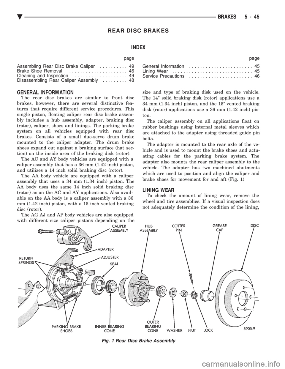
The rear disc brakes are similar to front disc
brakes, however, there are several distinctive fea-
tures that require different service procedures. This
single piston, floating caliper rear disc brake assem-
bly includes a hub assembly, adapter, braking disc
(rotor), caliper, shoes and linings. The parking brake
system on all vehicles equipped with rear disc
brakes. Consists of a small duo-servo drum brake
mounted to the caliper adapter. The drum brake
shoes expand out against a braking surface (hat sec-
tion) on the inside area of the braking disk (rotor). The AC and AY body vehicles are equipped with a
caliper assembly that has a 36 mm (1.42 inch) piston,
and utilizes a 14 inch solid braking disc (rotor). The AA body vehicle are equipped with a caliper
assembly that uses a 34 mm (1.34 inch) piston. The
AA body uses the same 14 inch solid braking disc
(rotor) as on the AC and AY applications. Also avail-
able on the AA body is a caliper assembly with a 36
mm (1.42 inch) piston, with a 15 inch vented braking
disc (rotor). The AG AJ and AP body vehicles are also equipped
with different size caliper pistons depending on the size and type of braking disk used on the vehicle.
The 14 9solid braking disk (rotor) applications use a
34 mm (1.34 inch) piston, and the 15 9vented braking
disk (rotor) applications use a 36 mm (1.42 inch) pis-
ton. The caliper assembly on all applications float on
rubber bushings using internal metal sleeves which
are attached to the adapter using threaded guide pin
bolts. The adapter is mounted to the rear axle of the ve-
hicle and is used to mount the brake shoes and actu-
ating cables for the parking brake system. The
adapter also mounts the rear caliper assembly to the
vehicle. The adapter has two machined abutments
which are used to position and align the caliper and
brake shoes for movement for and aft (Fig. 1)
LINING WEAR
To check the amount of lining wear, remove the
wheel and tire assemblies. If a visual inspection does
not adequately determine the condition of the lining,
Fig. 1 Rear Disc Brake Assembly
Ä BRAKES 5 - 45
Page 203 of 2438

BRAKE DISC (ROTOR) INDEX
page page
Braking Disc Removal ..................... 54
General Information ....................... 53
Inspection Diagnosis ...................... 53 Installing Braking Disc
..................... 54
Refinishing Braking Disc ................... 55
Service Procedures ....................... 53
GENERAL INFORMATION
Any servicing of the braking disc requires extreme
care to maintain the braking disc within service toler-
ances to ensure proper brake action.
CAUTION: If the braking disk (rotor) needs to be
replaced with a new part. The protective coating on
the braking surfaces of the rotor MUST BE REMOVED
with an appropriate solvent, to avoid contamination
of the brake shoe linings.
When replacing a rotor with a new part do NOT
reface the new rotor. Rotor already has the re-
quired micro finish when manufactured, only
remove the protective coating.
INSPECTION DIAGNOSIS
Before refinishing or refacing a braking disc, the disc
should be checked and inspected for the following
conditions: Braking surface scoring, rust, impregnation of lining
material and worn ridges. Excessive lateral rotor runout or wobble.
Thickness variation (Parallelism).
Dishing or distortion (Flatness).
If a vehicle has not been driven for a period of time.
The discs will rust in the area not covered by the brake
lining and cause noise and chatter when the brakes are
applied. Excessive wear and scoring of the disc can cause
temporary improper lining contact if ridges are not
removed before installation of new brake shoe assem-
blies. Some discoloration or wear of the disc surface is
normal and does not require resurfacing when linings
are replaced. Excessive runout or wobble in a disc can increase
pedal travel due to piston knock back. This will in-
crease guide pin bushing wear due to tendency of
caliper to follow disc wobble. Thickness variation in a disc can also result in pedal
pulsation, chatter and surge due to variation in brake
output. This can also be caused by excessive runout in
braking disc or hub. Dishing or distortion can be caused by extreme heat
and abuse of the brakes.
SERVICE PROCEDURES
CHECKING BRAKING DISC FOR RUNOUT AND THICKNESS
On vehicle, braking disc (rotor) runout is the com-
bination of the individual runout of the hub face and
the runout of the disc. (The hub and disc are separa-
ble). To measure runout on the vehicle, remove the
wheel and reinstall the lug nuts tightening the disc
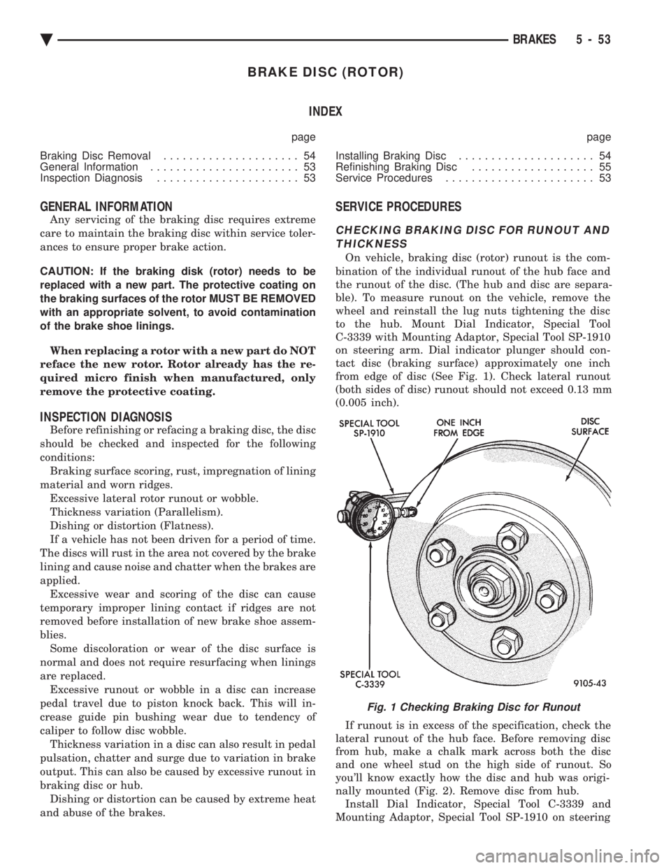
to the hub. Mount Dial Indicator, Special Tool
C-3339 with Mounting Adaptor, Special Tool SP-1910
on steering arm. Dial indicator plunger should con-
tact disc (braking surface) approximately one inch
from edge of disc (See Fig. 1). Check lateral runout
(both sides of disc) runout should not exceed 0.13 mm
(0.005 inch).
If runout is in excess of the specification, check the
lateral runout of the hub face. Before removing disc
from hub, make a chalk mark across both the disc
and one wheel stud on the high side of runout. So
you'll know exactly how the disc and hub was origi-
nally mounted (Fig. 2). Remove disc from hub. Install Dial Indicator, Special Tool C-3339 and
Mounting Adaptor, Special Tool SP-1910 on steering
Fig. 1 Checking Braking Disc for Runout
Ä BRAKES 5 - 53
Page 204 of 2438

knuckle. Position stem so it contacts hub face near
outer diameter. Care must be taken to position stem
outside the stud circle but inside the chamfer on the
hub rim. Clean hub surface before checking. (See
Fig. 3)
Runout should not exceed 0.08 mm (0.003 inch). If
runout exceeds this specification, hub must be re-
placed. See Suspension Group 2. If hub runout does
not exceed this specification, install disc on hub with
chalk marks two wheel studs apart (Fig. 4). Tighten
nuts in the proper sequence and torque to specifica-
tions. Finally, check runout of disc to see if runout is
now within specifications. If runout is not within specifications. Install a new
braking disc or reface disc, being careful to remove
as little as possible from each side of disc. Remove
equal amounts from each side of disc. Do not reduce
thickness below minimum thickness cast into the un-
machined surface of the rotor. Thickness variation measurements of disc should
be made in conjunction with runout. Measure thick-
ness of disc at 12 equal points with a micrometer at
a radius approximately 25.4 mm (1 inch) from edge
of disc (Fig. 5). If thickness measurements vary by
more than 0.013 mm (0.0005 inch) disc should be re-
moved and resurfaced (Figs. 6 and 7), or a new disc
installed. If cracks or burned spots are evident in the
disc, disc must be replaced. Light scoring and/or wear is acceptable. If heavy
scoring or warping is evident, the disc must be refin-
ished or replaced (See Refinishing/Refacing Braking
Disc). If cracks are evident in the disc, replace the
disc.
BRAKING DISC REMOVAL
(1) Raise vehicle on hoist or jackstands. Remove
wheel and tire assembly. (2) Remove caliper assembly, as described under
Brake Shoe Removal in this Group, (but do not dis-
connect brake line). Suspend caliper from wire hook
or loop to avoid strain on flexible hose. (3) Remove braking disc from the hub.
INSTALLING BRAKING DISC
(1) Slide braking disc on hub. Clean both sides of
braking disc with alcohol or suitable solvent. (2) Install caliper assembly, as described in Brake
Shoe Installation paragraph.
Fig. 2 Marking Braking Disc and Wheel Stud
Fig. 3 Checking Hub for Runout
Fig. 4 Index Braking Disc and Wheel Stud
5 - 54 BRAKES Ä
Page 207 of 2438

PARKING BRAKES INDEX
page page
Adjust Parking Brake (AG & AJ Body) ........ 61
General Information ....................... 57
Installing Parking Brake Front Cable (AA, AC, AP AY Body) ............................. 62
Installing Parking Brake Shoes .............. 64
Parking Brake Hand Lever Assembly Removal and Installation ............................ 63
Rear Parking Brake Cable Installation ......... 62 Rear Parking Brake Cable Removal (AA, AC, AP,
AY Body) ............................. 61
Removal and Installation Parking Brake Shoes . . 63
Removing Parking Brake Front Cable (AA, AC, AP, AY Body) ............................. 62
Self Adjusting Procedures (AG & AJ Body) ..... 61
Service Procedures ....................... 57
GENERAL INFORMATION
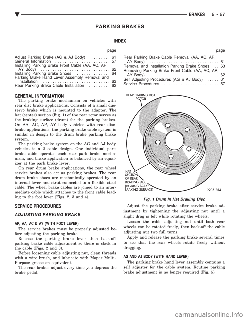
The parking brake mechanism on vehicles with
rear disc brake applications. Consists of a small duo-
servo brake which is mounted to the adapter. The
hat (center) section (Fig. 1) of the rear rotor serves as
the braking surface (drum) for the parking brakes.
On AA, AC, AP, AY body vehicles with rear disc
brake applications, the parking brake cable system is
similar in design to the drum brake parking brake
system. The parking brake system on the AG and AJ body
vehicles i s a 2 cable design. One individual park
brake cable operates each rear park brake mecha-
nism, and brake application is balanced by an equal-
izer at the park brake lever. On rear drum brake applications, the rear wheel
service brakes also act as parking brakes. The rear
drum brake shoes are mechanically operated by an
internal lever and strut connected to a flexible steel
cable. The wheel brake cables are joined to an inter-
mediate cable which attaches to the front cable lead-
ing to the foot lever (Figs. 2, 3 and 4).
SERVICE PROCEDURES
ADJUSTING PARKING BRAKE
AP, AA, AC & AY (WITH FOOT LEVER)
The service brakes must be properly adjusted be-
fore adjusting the parking brake. Release the parking brake lever then back-off
parking brake cable adjustment so there is slack in
the cable (Figs. 2 and 3). Before loosening cable adjusting nut, clean threads
with a wire brush, and lubricate with Mopar Multi-
Purpose grease on equivalent. The rear brakes adjust every time you depress the
brake pedal. Adjust the parking brake after service brake ad-
justment by tightening the adjusting nut until a
slight drag is felt while rotating the wheels. Loosen the cable adjusting nut until both rear
wheels can be rotated freely, then back-off the cable
adjusting nut two full turns. Apply and release the parking brake several times
to see that the rear wheels rotate freely without
dragging.
AG AND AJ BODY (WITH HAND LEVER) The parking brake hand lever assembly contains a
self adjuster for the cable system. Routine parking
brake adjustment is no longer required (Fig. 5).
Fig. 1 Drum In Hat Braking Disc
Ä BRAKES 5 - 57
Page 216 of 2438

MASTER CYLINDER INDEX
page page
Brake Fluid Level Sensor .................. 66
General Information ....................... 66 Master Cylinder Service Procedures
.......... 67
Testing the Master Cylinder ................. 66
GENERAL INFORMATION
The tandem master cylinder (Fig. 1) has a glass re-
inforced nylon reservoir and an anodized aluminum
body. Do not hone the bore of the cylinder, as this will
remove the anodized surface. The reservoir is indexed to prevent installation in
the wrong direction (Fig. 2). The cap diaphragms are
slit to allow atmospheric pressure to equalize on both
sides of the diaphragm. The primary and secondary outlet tubes from the
master cylinder are connected to the valve mounted
under the master cylinder. The front part of this
block connects to the secondary outlet tube and sup-
plies the right rear and left front brakes. The rear
portion of the block connects to the primary outlet
tube and supplies the right front and left rear
brakes.
BRAKE FLUID LEVEL SENSOR
The Brake Fluid Level sensor is found only in the
AJ body vehicles with the visual electronic message
center. The purpose of the sensor is to provide the
driver with an early warning message that brake
fluid in master cylinder reservoir has dropped to a
below normal. As the fluid drops below the design level the sensor
closes the warning message circuit. Approximately
15 seconds later the message BRAKE FLUID LOW
appears on the instrument panel. At this time the master cylinder reservoir should be checked and filled
to the bottom of the rings with DOT 3 brake fluid. To check the operation of the Brake Fluid Level
sensor, with ignition on and wiring still attache-
d,remove sensor from master cylinder and hold in
upright position. Within 30 seconds the instrument
panel message BRAKE FLUID LOW should appear.
Next invert the sensor. The instrument panel message
should turn off immediately. If the above sequence
occurs the sensor is operating properly. If the message
does not appear remove the wiring from the sensor and
using a jumper wire connect both sides of the plug. The
instrumental panel message BRAKE FLUID LOW
should appear within 30 seconds. If the message does
not appear a problem exists in the wiring or instru-
mentation. If the message does appear the sensor is
faulty and must be replaced. The Brake Fluid Level
sensor is not a repairable item (Fig. 2).
TESTING THE MASTER CYLINDER
Be sure master cylinder vents at both ports.
Apply pedal lightly with engine running and look for
fluid squirting or swirling into reservoirs. In this master cylinder, a special baffle reduces the
amount of fluid entering the secondary reservoir only a
small disturbance may be seen.
Fig. 1 Aluminum Master Cylinder (Cutaway View)
Fig. 2 Brake Fluid Level Sensor
5 - 66 BRAKES Ä
Page 222 of 2438

ANTI-LOCK BRAKE SYSTEMÐBENDIX ANTI-LOCK 10 AC/Y BODY INDEX
page page
ABS Brake System Diagnostic Features ....... 92
ABS Braking System Diagnosis .............. 87
ABS Controller Anti-Lock Brake (CAB) Service Precautions ........................... 88
ABS Equipped Vehicle Performance .......... 75
ABS Hydraulic Circuits and Valve Operation .... 85
ABS System Diagnostic Connector ........... 82
ABS System General Service Precautions ...... 88
ABS System Self-Diagnostics ............... 75
ABS Warning Systems Operation ............ 75
Anti-Lock Brake System Components ......... 76 Anti-Lock Brake System Definitions
........... 72
Anti-Lock Operation and Performance ......... 73
Anti-Lock System Relays and Warning Lamps . . . 82
Controller Anti-Lock Brake (CAB) ............. 80
Electronic Components ................... 103
General Information ....................... 72
General Service Precautions ................ 93
Major ABS Components ................... 73
Mechanical Diagnostics and Service Procedures . 89
Normal Braking System Function ............. 72
On Car Hydraulic ABS Component Service ..... 93
GENERAL INFORMATION
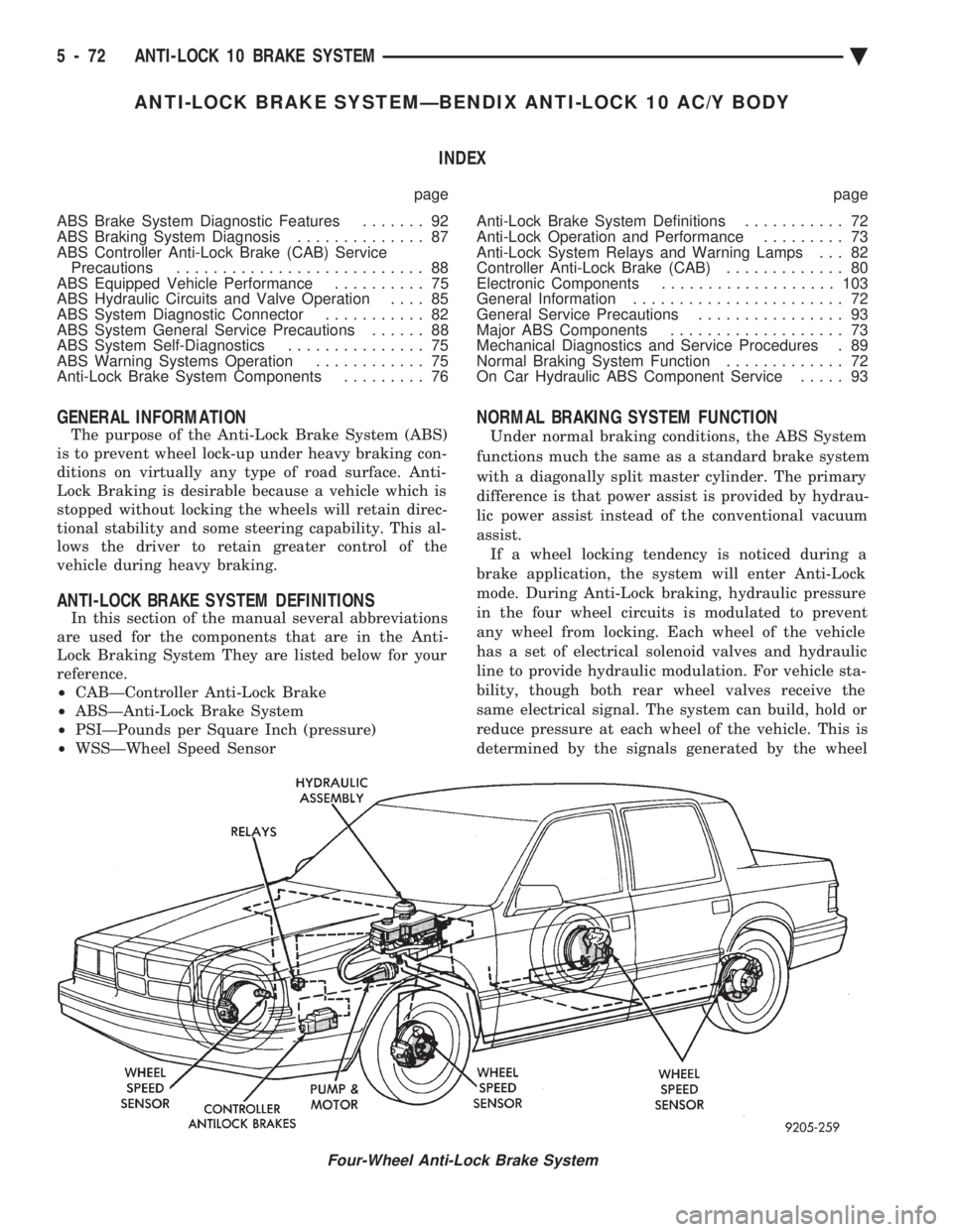
The purpose of the Anti-Lock Brake System (ABS)
is to prevent wheel lock-up under heavy braking con-
ditions on virtually any type of road surface. Anti-
Lock Braking is desirable because a vehicle which is
stopped without locking the wheels will retain direc-
tional stability and some steering capability. This al-
lows the driver to retain greater control of the
vehicle during heavy braking.
ANTI-LOCK BRAKE SYSTEM DEFINITIONS
In this section of the manual several abbreviations
are used for the components that are in the Anti-
Lock Braking System They are listed below for your
reference.
² CABÐController Anti-Lock Brake
² ABSÐAnti-Lock Brake System
² PSIÐPounds per Square Inch (pressure)
² WSSÐWheel Speed Sensor
NORMAL BRAKING SYSTEM FUNCTION
Under normal braking conditions, the ABS System
functions much the same as a standard brake system
with a diagonally split master cylinder. The primary
difference is that power assist is provided by hydrau-
lic power assist instead of the conventional vacuum
assist. If a wheel locking tendency is noticed during a
brake application, the system will enter Anti-Lock
mode. During Anti-Lock braking, hydraulic pressure
in the four wheel circuits is modulated to prevent
any wheel from locking. Each wheel of the vehicle
has a set of electrical solenoid valves and hydraulic
line to provide hydraulic modulation. For vehicle sta-
bility, though both rear wheel valves receive the
same electrical signal. The system can build, hold or
reduce pressure at each wheel of the vehicle. This is
determined by the signals generated by the wheel
Four-Wheel Anti-Lock Brake System
5 - 72 ANTI-LOCK 10 BRAKE SYSTEM Ä
Page 263 of 2438

ANTI-LOCK BRAKE SYSTEMÐBENDIX ANTI-LOCK 6 AA,AG,AJ,AP BODY INDEX
page page
ABS Brake System Diagnosis .............. 123
ABS Brake System Diagnostic Features ...... 125
ABS Computer System Service Precautions . . . 124
ABS General Service Precautions ........... 124
Anti-Lock Brake System Components ........ 116
Anti-Lock Brake System Definitions .......... 113
Anti-Lock Brakes Operation and Performance . . 115
Anti-Lock System Relays and Warning Lamps . . 120
Controller Anti-Lock Brake (CAB) ............ 119
Diagnostic Connector ..................... 120
Electronic Components ................... 130 General Information
...................... 113
Hydraulic Circuits and Valve Operation ....... 121
Major Components ...................... 114
Mechanical Diagnostics and Service Procedures . 125
Normal Braking System Function ............ 114
On-Car ABS Brake System Service .......... 126
Specifications .......................... 135
System Self-Diagnostics .................. 115
Vehicle Performance ..................... 115
Warning Systems Operation ............... 116
GENERAL INFORMATION
The purpose of the Anti-Lock Brake System (ABS)
is to prevent wheel lock-up under heavy braking con-
ditions on virtually any type of road surface. Anti-
Lock Braking is desirable because a vehicle which is
stopped without locking the wheels will retain direc-
tional stability and some steering capability. This al-
lows the driver to retain greater control of the
vehicle during heavy braking. This section of the service manual covers the de-
scription, diagnostics, and on car service for the Ben-
dix Anti-Lock 6 Brake System. If other service is required on the non ABS related components of the
brake system. Refer to the appropriate section in this
group of the manual for the specific service procedure
required.
ANTI-LOCK BRAKE SYSTEM DEFINITIONS
In this section of the manual several abbreviations
are used for the components that are in the Anti-
Lock Braking System They are listed below for your
reference.
² CABÐController Anti-Lock Brake
² ABSÐAnti-Lock Brake System
Fig. 1 Four-Wheel Anti-Lock Brake System Components AA/AG/AJ Body
Ä ANTI-LOCK 6 BRAKE SYSTEM 5 - 113
Page 289 of 2438

SERVICE ADJUSTMENTS INDEX
page page
Bleeding Bendix Antilock 4 Brake System ....... 3
Master Cylinder Fluid Level .................. 3 Testing for Fluid Contamination
............... 4
MASTER CYLINDER FLUID LEVEL
Check master cylinder reservoir brake fluid level a
minimum of two times a year. Master cylinder reservoirs are marked with the
words fill to bottom of rings indicating proper fluid
level (Fig. 4). Use only Mopar tbrake fluid or an equivalent from
a sealed container. Brake fluid must conform to DOT
3, specifications. Use only brake fluid that was stored in a tightly-
sealed container.
CAUTION: DO NOT use petroleum-based fluid be-
cause seal damage in the brake system will result.
CAUTION: DO NOT use brake fluid with a lower
boiling point, as brake failure could result during
prolonged hard braking.
If necessary add only an approved brake fluid to
master cylinder fluid reservoir until filled to the
proper level. Correct master cylinder fluid reservoir
fill level is to the bottom of the primary reservoir
split ring.
BLEEDING BENDIX ANTILOCK 4 BRAKE SYSTEM
CAUTION: When bleeding the Bendix Antilock 4
Brake System hydraulic circuits, refer to the Bendix
Antilock 4 Brake System bleeding procedure in this
service manual supplement.
BASE BRAKE SYSTEM BLEEDING PROCEDURE
CAUTION: The base brakes hydraulic system, on a
vehicle equipped with a Bendix Antilock 4 Brake
System, can NOT be bled using a brake hydraulic
system pressure bleeder. This type of pressure
bleeding equipment, does not develop the pressure
required in the brake hydraulic system, to ade-
quately bleed all trapped air. The only approved
method of bleeding the base brakes hydraulic sys-
tem, on vehicles equipped with a Bendix Antilock 4
Brake System, is the manual procedure of pressur-
izing the hydraulic system using constant moderate
to heavy foot pressure on the brake pedal.
When bleeding brake hydraulic systems, some air
may be trapped in brake lines or valves as far as ten
feet from the bleeder screw (Fig. 5). Therefore, it is
essential to have a fast flow of a large volume of
brake fluid when bleeding the brakes. This will en-
sure all trapped air is completely bled out of the
brakes hydraulic system.
To bleed the base brake hydraulic system. Attach a
clear plastic hose to the bleeder screw starting at the
right rear wheel and feed the hose into a clear jar
containing fresh brake fluid (Fig. 6). The following wheel sequence when bleeding the
base brakes hydraulic system should be used. This
sequence will ensure adequate removal of all trapped
air from the hydraulic system.
² Right rear wheel
² Left front wheel
Fig. 4 Master Cylinder Fluid Level
Fig. 5 Trapped Air in Brake Line
Ä BRAKES 5 - 3