1993 CHEVROLET PLYMOUTH ACCLAIM Index
[x] Cancel search: IndexPage 52 of 2438

DRIVETRAIN INDEX
page page
Automatic Transaxle ...................... 16
Automatic Transaxle Floor Shift .............. 16
Clutch and Gearshift Linkage ............... 16
Drive Shaft Cv and Tripod Joint Boots ........ 17 Front Wheel Bearings
..................... 17
Manual Transaxle ........................ 16
Tires .................................. 17
CLUTCH AND GEARSHIFT LINKAGE
If the clutch or gearshift begins to operate with dif-
ficulty, squeak or grunt, the cables and linkage
should be lubricated before service replacement is
performed. For proper lubrication and service proce-
dures refer to Group 6, Clutch, or Group 21, Manual
Transaxle.
MANUAL TRANSAXLE
The manual transaxle should be inspected for oil
leaks and proper oil level when other under vehicle
service is performed. To inspect the transaxle oil
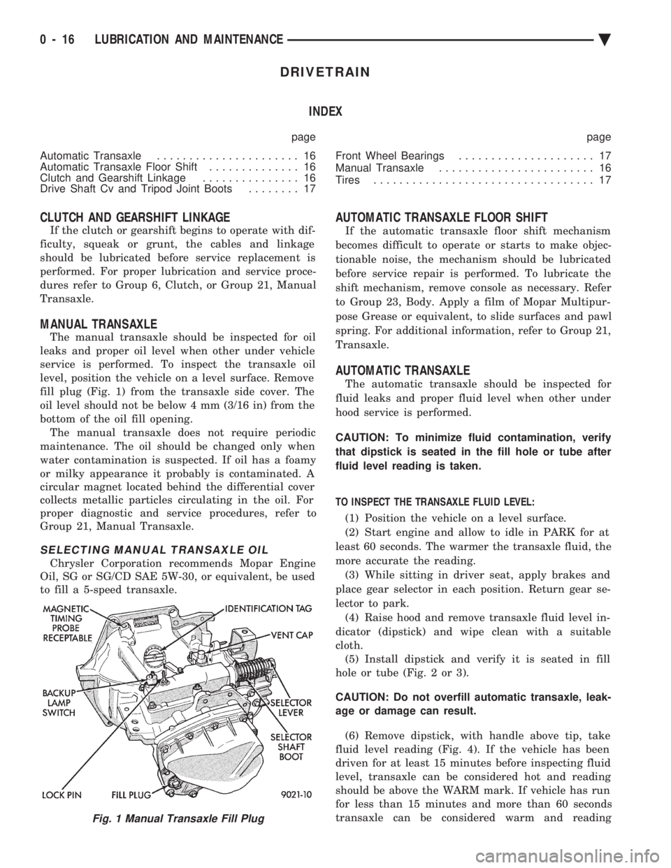
level, position the vehicle on a level surface. Remove
fill plug (Fig. 1) from the transaxle side cover. The
oil level should not be below 4 mm (3/16 in) from the
bottom of the oil fill opening. The manual transaxle does not require periodic
maintenance. The oil should be changed only when
water contamination is suspected. If oil has a foamy
or milky appearance it probably is contaminated. A
circular magnet located behind the differential cover
collects metallic particles circulating in the oil. For
proper diagnostic and service procedures, refer to
Group 21, Manual Transaxle.
SELECTING MANUAL TRANSAXLE OIL
Chrysler Corporation recommends Mopar Engine
Oil, SG or SG/CD SAE 5W-30, or equivalent, be used
to fill a 5-speed transaxle.
AUTOMATIC TRANSAXLE FLOOR SHIFT
If the automatic transaxle floor shift mechanism
becomes difficult to operate or starts to make objec-
tionable noise, the mechanism should be lubricated
before service repair is performed. To lubricate the
shift mechanism, remove console as necessary. Refer
to Group 23, Body. Apply a film of Mopar Multipur-
pose Grease or equivalent, to slide surfaces and pawl
spring. For additional information, refer to Group 21,
Transaxle.
AUTOMATIC TRANSAXLE
The automatic transaxle should be inspected for
fluid leaks and proper fluid level when other under
hood service is performed.
CAUTION: To minimize fluid contamination, verify
that dipstick is seated in the fill hole or tube after
fluid level reading is taken.
TO INSPECT THE TRANSAXLE FLUID LEVEL: (1) Position the vehicle on a level surface.
(2) Start engine and allow to idle in PARK for at
least 60 seconds. The warmer the transaxle fluid, the
more accurate the reading. (3) While sitting in driver seat, apply brakes and
place gear selector in each position. Return gear se-
lector to park. (4) Raise hood and remove transaxle fluid level in-
dicator (dipstick) and wipe clean with a suitable
cloth. (5) Install dipstick and verify it is seated in fill
hole or tube (Fig. 2 or 3).
CAUTION: Do not overfill automatic transaxle, leak-
age or damage can result.
(6) Remove dipstick, with handle above tip, take
fluid level reading (Fig. 4). If the vehicle has been
driven for at least 15 minutes before inspecting fluid
level, transaxle can be considered hot and reading
should be above the WARM mark. If vehicle has run
for less than 15 minutes and more than 60 seconds
transaxle can be considered warm and reading
Fig. 1 Manual Transaxle Fill Plug
0 - 16 LUBRICATION AND MAINTENANCE Ä
Page 55 of 2438

CHASSIS AND BODY INDEX
page page
Body Lubrication ......................... 22
Brakes ................................ 21
Headlamps ............................. 22
Lower Ball Joints ......................... 19 Power Steering
.......................... 19
Rear Wheel Bearings ..................... 20
Steering Linkage ......................... 19
STEERING LINKAGE
INSPECTION
The steering linkage and steering gear should be in-
spected for wear, leaks or damage when other under ve-
hicle service is performed. The rack and pinion steering
gear end boots should not have excess oil or grease res-
idue on the outside surfaces or surrounding areas
(Fig.1). If boot is leaking, it should be repaired. For
proper service procedures, see Group 19, Steering.
The tie rod end seal should fit securely between the
steering knuckle and tie rod end (Fig.2). The steering
linkage should be lubricated at the time and distance
intervals described in the Lubrication and Mainte-
nance Schedules. Refer to General Information sec-
tion of this group.
TIE ROD END LUBRICATION
Lubricate the steering linkage with Mopar, Multi-
mileage Lube or equivalent. Using a wiping cloth,
clean grease and dirt from around grease fitting and
joint seal. Using a grease gun, fill tie rod end until
lubricant leaks from around the tie rod end side of
the seal (Fig.2). When lube operation is complete,
wipe off excess grease.
LOWER BALL JOINTS
INSPECTION
The front suspension lower ball joints should be in-
spected for wear, leaks or damage when other under ve- hicle service is performed. The ball joint seal should fit
securely between the steering knuckle and lower control
arm (Fig. 3). The ball joints should be lubricated at the
time and distance intervals described in the Lubrication
and Maintenance Schedules. Refer to the General Infor-
mation section of this group.
BALL JOINT LUBRICATION
CAUTION: Do not over fill ball joint with grease,
damage to seal can result.
Lubricate the ball joints with Mopar, Multi-mile-
age Lube or equivalent. Using a wiping cloth, clean
grease and dirt from around grease fitting and joint
seal. Using a grease gun, fill ball joint until seal
starts to swell (Fig. 3). When lube operation is com-
plete, wipe off excess grease.
POWER STEERING
The power steering fluid level should be inspected
when other under hood service is performed. If the
fluid level is low and system is not leaking, use Mo-
par, Power Steering Fluid or equivalent. The power
steering system should be inspected for leaks when
other under vehicle service is performed. For proper
service procedures, refer to Group 19, Steering.Fig. 1 Inspect Steering Linkage
Fig. 2 Tie Rod End Lubrication
Ä LUBRICATION AND MAINTENANCE 0 - 19
Page 63 of 2438

FRONT SUSPENSION SERVICE PROCEDURES INDEX
page page
Ball Joints .............................. 13
Hub and Bearing Assembly ................. 20
Knuckle (Front Suspension) ................. 16
Lower Control Arm ....................... 10
Lower Control Arm Pivot Bushings ........... 11 Shock Absorbers (Strut Damper)
............. 10
Strut Damper Assembly ..................... 7
Suspension Coil Springs .................... 9
Sway Bar .............................. 14
Wheel Alignment .......................... 5
WHEEL ALIGNMENT
Front wheel alignment is the proper adjustment of
all interrelated front suspension angles. These angles
are what affects the running and steering of the
front wheels of the vehicle. The method of checking front alignment will vary
depending on the type of equipment being used. The
instructions furnished by the manufacturer of the
equipment should always be followed. With the ex-
ception that the alignment specifications recom-
mended by Chrysler Corporation be used. There are six basic factors which are the founda-
tion to front wheel alignment. These are height,
caster, camber, toe-in, steering axis inclination and
toe-out on turns. Of the six basic factors only camber
and toe in are mechanically adjustable (Fig. 1)
CAUTION: Do not attempt to modify any suspen-
sion or steering components by heating or bending
of the component.
Wheel alignment adjustments and checks should be
made in the following sequence. (1) Camber
(2) Toe
Camber is the number of degrees the top of the
wheel is tilted inward or outward from true vertical.
Inward tilt is negative camber. Outward tilt is posi-
tive camber. Excessive camber is a tire wear factor: negative
camber causes wear on the inside of the tire, while
positive camber causes wear to the outside. Toe
is measured in degrees or inches and is the
distance the front edges of the tires are closer (or far-
ther apart) than the rear edges. See Front Wheel
Drive Specifications for Toesettings.
PRE-ALIGNMENT
Before any attempt is made to change or correct
the wheel alignment factors. The following inspection
and necessary corrections must be made on those
parts which influence the steering of the vehicle. (1) Check and inflate tires to recommended pres-
sure. All tires should be the same size and in good
condition and have approximately the same wear.
Note type of tread wear which will aid in diagnosing,
see Wheels and Tires, Group 22. (2) Check front wheel and tire assembly for radial
runout. (3) Inspect lower ball joints and all steering link-
age for looseness. (4) Check for broken or sagged front and rear
springs. Front suspension must only be checked after the
vehicle has had the following checked or adjusted.
Tires set to recommended pressures, full tank of fuel,
no passenger or luggage compartment load and is on
a level floor or alignment rack. Just prior to each alignment reading. The vehicle
should be bounced (rear first, then front) by grasping
bumper at center and jouncing each end an equal
number of times. Always release bumpers at bottom
of down cycle.
Ä SUSPENSION AND DRIVESHAFTS 2 - 5
Page 66 of 2438

INSPECTION
Inspect for evidence of fluid running from the up-
per end of the reservoir. (Actual leakage will be a
stream of fluid running down the side and dripping
off lower end of unit). A slight amount of seepage be-
tween the strut rod and strut shaft seal is not un-
usual and does not affect performance of the strut
assembly.
INSTALLATION
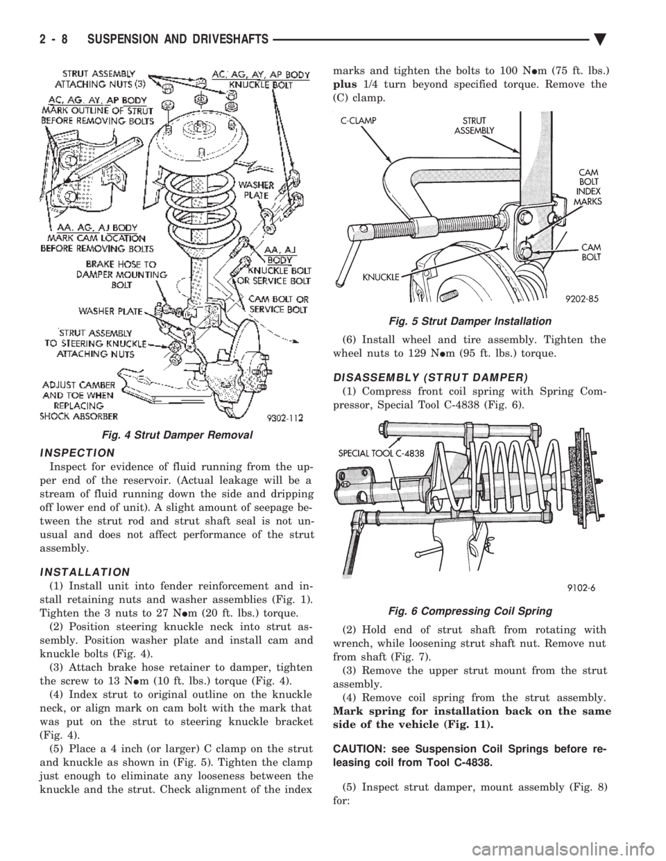
(1) Install unit into fender reinforcement and in-
stall retaining nuts and washer assemblies (Fig. 1).
Tighten the 3 nuts to 27 N Im (20 ft. lbs.) torque.
(2) Position steering knuckle neck into strut as-
sembly. Position washer plate and install cam and
knuckle bolts (Fig. 4). (3) Attach brake hose retainer to damper, tighten
the screw to 13 N Im (10 ft. lbs.) torque (Fig. 4).
(4) Index strut to original outline on the knuckle
neck, or align mark on cam bolt with the mark that
was put on the strut to steering knuckle bracket
(Fig. 4). (5) Plac e a 4 inch (or larger) C clamp on the strut
and knuckle as shown in (Fig. 5). Tighten the clamp
just enough to eliminate any looseness between the
knuckle and the strut. Check alignment of the index marks and tighten the bolts to 100 N
Im (75 ft. lbs.)
plus 1/4 turn beyond specified torque. Remove the
(C) clamp.
(6) Install wheel and tire assembly. Tighten the
wheel nuts to 129 N Im (95 ft. lbs.) torque.
DISASSEMBLY (STRUT DAMPER)
(1) Compress front coil spring with Spring Com-
pressor, Special Tool C-4838 (Fig. 6).
(2) Hold end of strut shaft from rotating with
wrench, while loosening strut shaft nut. Remove nut
from shaft (Fig. 7). (3) Remove the upper strut mount from the strut
assembly. (4) Remove coil spring from the strut assembly.
Mark spring for installation back on the same
side of the vehicle (Fig. 11).
CAUTION: see Suspension Coil Springs before re-
leasing coil from Tool C-4838.
(5) Inspect strut damper, mount assembly (Fig. 8)
for:
Fig. 4 Strut Damper Removal
Fig. 5 Strut Damper Installation
Fig. 6 Compressing Coil Spring
2 - 8 SUSPENSION AND DRIVESHAFTS Ä
Page 83 of 2438

DRIVESHAFTS INDEX
page page
C/V Joint Boots Handling and Cleaning ........ 44
Damper Weights ......................... 48
Driveshaft Identification .................... 27
Driveshaft Positioning Specifications .......... 48
Driveshaft Reconditioning Procedure .......... 31
Driveshafts, Remove Install ................. 27 General Information
....................... 25
Inner C/V Joint .......................... 32
Intermediate Shaft Assembly Recondition ...... 41
Outer C/V Joint .......................... 37
Service Procedures ....................... 27
GENERAL INFORMATION
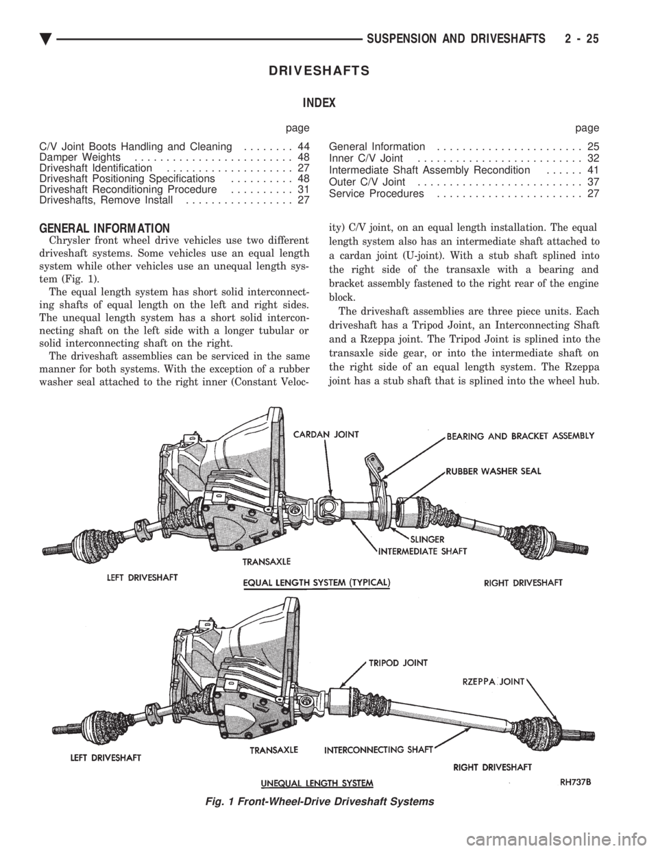
Chrysler front wheel drive vehicles use two different
driveshaft systems. Some vehicles use an equal length
system while other vehicles use an unequal length sys-
tem (Fig. 1). The equal length system has short solid interconnect-
ing shafts of equal length on the left and right sides.
The unequal length system has a short solid intercon-
necting shaft on the left side with a longer tubular or
solid interconnecting shaft on the right.
The driveshaft assemblies can be serviced in the same
manner for both systems. With the exception of a rubber
washer seal attached to the right inner (Constant Veloc- ity) C/V joint, on an equal length installation. The equal
length system also has an intermediate shaft attached to
a cardan joint (U-joint). With a stub shaft splined into
the right side of the transaxle with a bearing and
bracket assembly fastened to the right rear of the engine
block.
The driveshaft assemblies are three piece units. Each
driveshaft has a Tripod Joint, an Interconnecting Shaft
and a Rzeppa joint. The Tripod Joint is splined into the
transaxle side gear, or into the intermediate shaft on
the right side of an equal length system. The Rzeppa
joint has a stub shaft that is splined into the wheel hub.
Fig. 1 Front-Wheel-Drive Driveshaft Systems
Ä SUSPENSION AND DRIVESHAFTS 2 - 25
Page 108 of 2438

REAR SUSPENSION INDEX
page page
Coil Springs and Jounce Bumper ............ 51
General Information ....................... 50
Pivot Bushing AC AG AJ AP Body ........... 55
Pivot Bushing AC and AY Body ............. 52 Rear Axle Assembly
...................... 57
Shock Absorbers ......................... 51
Track Bar-Brace-Bracket ................... 52
GENERAL INFORMATION
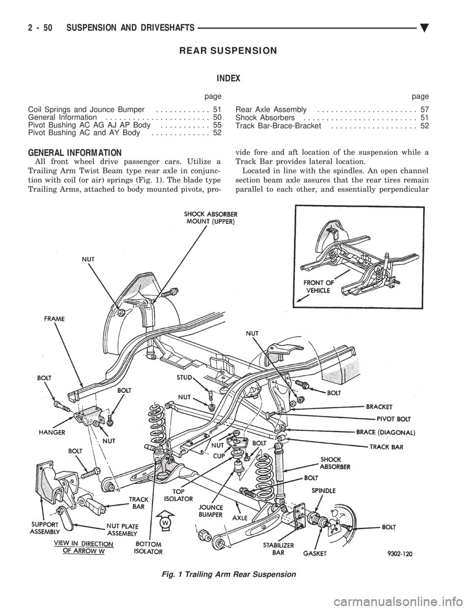
All front wheel drive passenger cars. Utilize a
Trailing Arm Twist Beam type rear axle in conjunc-
tion with coil (or air) springs (Fig. 1). The blade type
Trailing Arms, attached to body mounted pivots, pro- vide fore and aft location of the suspension while a
Track Bar provides lateral location. Located in line with the spindles. An open channel
section beam axle assures that the rear tires remain
parallel to each other, and essentially perpendicular
Fig. 1 Trailing Arm Rear Suspension
2 - 50 SUSPENSION AND DRIVESHAFTS Ä
Page 117 of 2438

AUTOMATIC AIR LOAD LEVELING SYSTEM INDEX
page page
Compressor Performance Test .............. 61
Compressor Relay ........................ 72
Control Module .......................... 72
General Information ....................... 59
Major Components ....................... 59 Rear Leveling Diagnostic Procedures
......... 65
Right Shock Absorber (With Height Sensor) .... 72
Service Procedures ....................... 62
System Operation ........................ 61
GENERAL INFORMATION
The automatic air load leveling system includes
the following (Fig. 1).:
² Compressor Assembly
² Control Module Wiring Harness
² Air Lines
² Compressor Relay
² Air Shock Absorbers
² Air Dryer
This system is used to supplement standard sus-
pension systems on vehicles so equipped.
MAJOR COMPONENTS
COMPRESSOR ASSEMBLY
The compressor assembly is driven by an electric
motor and supplies air pressure between 1172 to
1516 kPa (170 to 220 psi) (Fig. 2). A solenoid oper-
ated exhaust valve, located in the compressor head
assembly, releases air when energized.
CONTROL MODULE
The Control Module (CM) is a device that controls
the ground circuits for the compressor relay and the
exhaust valve solenoid. A microprocessor within the
module limits the compressor pump operation time to
140 to 160 seconds. To prevent damage to the com-
pressor motor.
Fig. 1 Automatic Air Load Leveling System
Ä SUSPENSION AND DRIVESHAFTS 2 - 59
Page 131 of 2438

AUTOMATIC AIR SUSPENSION INDEX
page page
Air Lines ............................... 75
Air Springs Rear ......................... 87
Compressor Performance Test .............. 77
Diagnosis .............................. 78
General Information ....................... 73
Recharge Air Spring ...................... 87 Right Shock Absorber (With Height Sensor)
.... 88
Safety Concerns ......................... 78
Service Procedures ....................... 85
Shipping Mode .......................... 78
Solenoids (Struts and Air Springs) ............ 86
System Operation ........................ 78
GENERAL INFORMATION
This system provides automatic height control and
low spring rates to improve suspension characteristics
of the vehicle. And it will automatically level the front
and rear of the vehicle. It will also maintain the opti-
mum vehicle attitude from one passenger through full
vehicle load.
The automatic air suspension system includes the
following components:
² Compressor/air dryer assembly
² Compressor relay
² Front struts
² Rear springs
² Rear shocks
² Control module
² Air lines ²
Compressor
² Rear height sensor
² Wiring harness assembly
² Compressor cover
Front springs (and height sensors) are integral with
the shock absorber strut assemblies. While rear air
springs replace conventional steel units. Rear height is
controlled via a height sensor contained within the
right rear shock absorber. Solenoids (integral with each
air spring) control air volume/pressure requirements.
Pressurized air is distributed from the air compressor/
dryer assembly and routed to each air spring by four
separate air lines. The air lines start at the dryer and
terminate at the individual air springs. The system is
monitored and controlled by the Air Suspension Control
Module (ASCM) (Fig. 1).
Fig. 1 Automatic Air Suspension
Ä SUSPENSION AND DRIVESHAFTS 2 - 73