1993 CHEVROLET PLYMOUTH ACCLAIM Index
[x] Cancel search: IndexPage 395 of 2438

FAULT CODESÐON BOARD DIAGNOSTICS INDEX
page page
Diagnostic Testing Using Fault Codes ......... 24
Drb II Diagnostic Tester ................... 24 General Description/Information
.............. 23
GENERAL DESCRIPTION/INFORMATION
Another way of diagnosing charging system prob-
lems can be accomplished using the On Board Diag-
nostic System Fault Codes. A Fault Code shows a potential problem in a mon-
itored circuit, or a condition caused by a faulty component. A
Fault Code can be retrieved by turning the ignition
switch ON-OFF-ON-OFF-ON without starting the
engine, and counting the number of flashes of the
Malfunction Indicator (CHECK ENGINE) Lamp in
the instrument cluster.
EXAMPLES:
² If the Malfunction Indicator (Check Engine) Lamp
flashes four times, pauses, and flashes one more
time, a Code 41 is shown. The first set of four flashes
indicates number four. The second set of one flash in-
dicates one.
² If the Malfunction Indicator (Check Engine) Lamp
flashes four times, pauses, and flashes six more
times, a Code 46 is shown. The first set of four
flashes indicates number four. The second set of six
flashes indicates six.
² If the Malfunction Indication (Check Engine)
Lamp flashes four times, pauses, and flashes seven
more times, a Code 47 is shown. The first set of four
flashes indicates number four. The second set of
seven flashes indicates seven. POWERTRAIN CONTROL MODULE
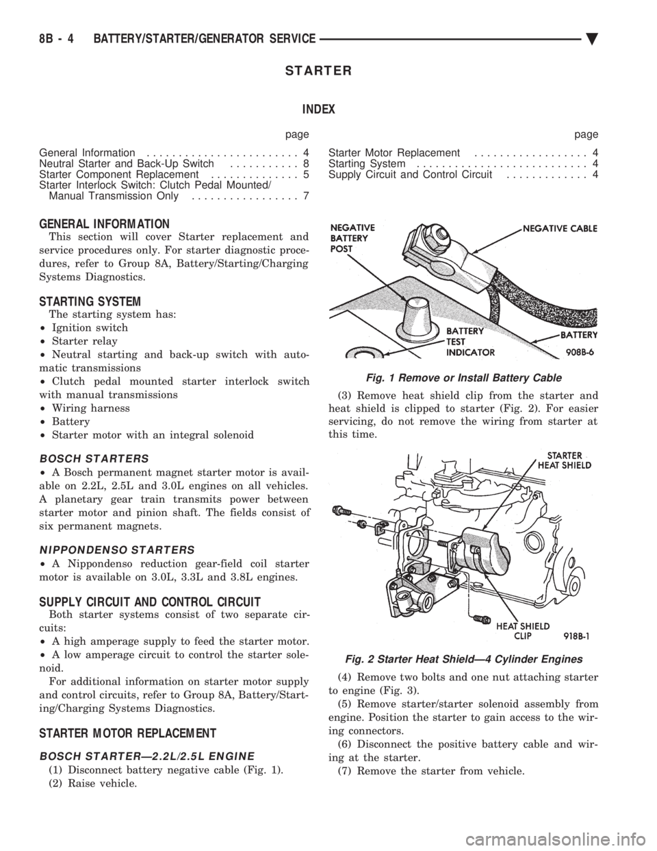
The Powertrain Control Module is equipped with
On Board Diagnostic features and monitors all en-
gine control circuits during a run/drive period. If a
circuit or system does not perform properly, the pow-
ertrain control module will file in memory a preset
Fault Code. This can be used to help in diagnosing a
problem. After 50 to 100 ignition switch ON/RUN cy-
cles, the memory will be erased if the fault does not
reoccur. The Powertrain Control Module is located in the
engine compartment outboard of the battery (Fig. 7).
Refer to Fig. 8 Generator Fault Codes Chart for re-
lationships of generator/charging system Fault Code
numbers.
Fig. 7 Powertrain Control Module
Ä BATTERY/STARTING/CHARGING SYSTEMS DIAGNOSTICS 8A - 23
Page 406 of 2438

STARTER INDEX
page page
General Information ........................ 4
Neutral Starter and Back-Up Switch ........... 8
Starter Component Replacement .............. 5
Starter Interlock Switch: Clutch Pedal Mounted/ Manual Transmission Only ................. 7 Starter Motor Replacement
.................. 4
Starting System ........................... 4
Supply Circuit and Control Circuit ............. 4
GENERAL INFORMATION
This section will cover Starter replacement and
service procedures only. For starter diagnostic proce-
dures, refer to Group 8A, Battery/Starting/Charging
Systems Diagnostics.
STARTING SYSTEM
The starting system has:
² Ignition switch
² Starter relay
² Neutral starting and back-up switch with auto-
matic transmissions
² Clutch pedal mounted starter interlock switch
with manual transmissions
² Wiring harness
² Battery
² Starter motor with an integral solenoid
BOSCH STARTERS
²A Bosch permanent magnet starter motor is avail-
able on 2.2L, 2.5L and 3.0L engines on all vehicles.
A planetary gear train transmits power between
starter motor and pinion shaft. The fields consist of
six permanent magnets.
NIPPONDENSO STARTERS
² A Nippondenso reduction gear-field coil starter
motor is available on 3.0L, 3.3L and 3.8L engines.
SUPPLY CIRCUIT AND CONTROL CIRCUIT
Both starter systems consist of two separate cir-
cuits:
² A high amperage supply to feed the starter motor.
² A low amperage circuit to control the starter sole-
noid. For additional information on starter motor supply
and control circuits, refer to Group 8A, Battery/Start-
ing/Charging Systems Diagnostics.
STARTER MOTOR REPLACEMENT
BOSCH STARTERÐ2.2L/2.5L ENGINE
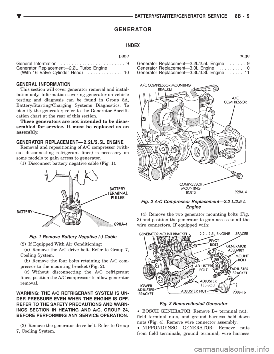
(1) Disconnect battery negative cable (Fig. 1).
(2) Raise vehicle. (3) Remove heat shield clip from the starter and
heat shield is clipped to starter (Fig. 2). For easier
servicing, do not remove the wiring from starter at
this time.
(4) Remove two bolts and one nut attaching starter
to engine (Fig. 3). (5) Remove starter/starter solenoid assembly from
engine. Position the starter to gain access to the wir-
ing connectors. (6) Disconnect the positive battery cable and wir-
ing at the starter. (7) Remove the starter from vehicle.
Fig. 1 Remove or Install Battery Cable
Fig. 2 Starter Heat ShieldÐ4 Cylinder Engines
8B - 4 BATTERY/STARTER/GENERATOR SERVICE Ä
Page 411 of 2438

GENERATOR INDEX
page page
General Information ........................ 9
Generator ReplacementÐ2.2L Turbo Engine (With 16 Valve Cylinder Head) ............. 10 Generator ReplacementÐ2.2L/2.5L Engine
...... 9
Generator ReplacementÐ3.0L Engine ......... 10
Generator ReplacementÐ3.3L/3.8L Engine ..... 11
GENERAL INFORMATION
This section will cover generator removal and instal-
lation only. Information covering generator on-vehicle
testing and diagnosis can be found in Group 8A,
Battery/Starting/Charging Systems Diagnostics. To
identify the generator, refer to the Generator Specifi-
cation chart at the rear of this section. These generators are not intended to be disas-
sembled for service. It must be replaced as an
assembly.
GENERATOR REPLACEMENTÐ2.2L/2.5L ENGINE
Removal and repositioning of A/C compressor (with-
out disconnecting refrigerant lines) is necessary on
some models to gain access to generator. (1) Disconnect battery negative cable (Fig. 1).
(2) If Equipped With Air Conditioning:
(a) Remove the A/C drive belt. Refer to Group 7,
Cooling System. (b) Remove the four bolts retaining the A/C com-
pressor to the mounting bracket (Fig. 2). (c) Without disconnecting the A/C refrigerant
lines, position the A/C compressor to allow generator
removal.
WARNING: THE A/C REFRIGERANT SYSTEM IS UN-
DER PRESSURE EVEN WHEN THE ENGINE IS OFF.
REFER TO THE SAFETY PRECAUTIONS AND WARN-
INGS SECTION IN HEATING AND A/C, GROUP 24,
BEFORE PERFORMING ANY SERVICE OPERATION. (3) Remove the generator drive belt. Refer to Group
7, Cooling System. (4) Remove the two generator mounting bolts (Fig.
3) and position the generator to gain access to all the
wire connectors. If equipped with:
² BOSCH GENERATOR: Remove B+ terminal nut,
field terminal nuts, and ground harness hold down
nuts (Fig. 4). Remove wire connector assembly.
² NIPPONDENSO GENERATOR: Remove nuts
from field terminals, ground terminal, wire harness
Fig. 1 Remove Battery Negative (-) Cable
Fig. 2 A/C Compressor ReplacementÐ2.2 L/2.5 L Engine
Fig. 3 Remove/Install Generator
Ä BATTERY/STARTER/GENERATOR SERVICE 8B - 9
Page 417 of 2438

OVERHEAD CONSOLE
CONTENTS
page page
AA BODY .............................. 1
AC AND AY BODY ....................... 6 AG AND AJ BODIES
.................... 13
AP BODY ............................. 21
GENERAL INFORMATION AA BODY
INDEX
page page
Ambient Temperature Sensor ................ 6
Compass Calibration ....................... 2
Compass Diagnostics ...................... 5
Compass Module Replacement ............... 6
Demagnetizing Procedure ................... 4 Map Reading Lamps
....................... 1
Overhead Console Replacement .............. 5
Self-Diagnostic Test ....................... 5
Thermometer and Compass Operation ......... 1
Variance ................................ 2
MAP READING LAMPS
The map reading and rear passenger lamps are
turned on and off by pressing their individual switch
marked LAMP. These same lamps also serve as cour-
tesy lamps whenever a door is opened, the illumi-
nated entry system is activated, or the headlamp
switch is turned fully clockwise.
LAMP REPLACEMENT
(1) Remove lens by inserting a large paper clip or
wire, with a hook on the end, into the hole in the
lens and pull downward (Fig. 1).
(2) Remove lamp by pulling firmly toward front of
vehicle. (3) Install new lamp by pushing firmly into recep-
tacle. (4) Snap lens into position taking care to orient
the tabs on the lens with the slots in the housing and
snap into position.
LAMP TEST
(1) Close vehicle doors.
(2) Press each lamp switch button (Fig.2). Right
hand button should light passenger side lamp and
left hand button should light drivers side lamp front
or rear. (3) If any of the lamps fail to illuminate, open ve-
hicle doors: (a) If lamp does not illuminate check for a
burned out lamp. If lamp is OK, check fuse and
wire connectors. (b) If lamp illuminates when doors are open
check switch.
THERMOMETER AND COMPASS OPERATION
The ignition switch must be in the ON or ACCES-
SORY position before the temperature and compass
reading can be displayed. The Comp/Temp switch, lo-
cated left of the display module, turns the display on
and off. The US/Metric switch, located right of the dis-
play, changes the temperature reading from Fahrenheit
to Celsius. Should the compass blank out and the CAL
symbol only light, demagnetizing may be necessary.
The compass is a flux-gate system which, is inte-
gral to the console. The temperature readout is con-
nected to a thermistor sensor which, located on the
front lower radiator closure panel.Fig. 1 Overhead Console Lens Removal
Ä OVERHEAD CONSOLE 8C - 1
Page 422 of 2438

COMPASS MODULE REPLACEMENT
(1) Remove overhead console.
(2) Using a small screwdriver, release the 2 snaps
at rear of compass module. (3) After releasing the 2 snaps, slide compass mod-
ule rearward until free of mounting bar. (4) For installation reverse above procedures.
AMBIENT TEMPERATURE SENSOR
(1) Raise and support vehicle on safety stands.
(2) From behind front bumper fascia, remove screw
attaching sensor to front lower crossmember (Fig. 7). (3) For installation, reverse above procedures.
AC AND AY BODY
INDEX
page page
Ambient Temperature Sensor ............... 12
Automatic Calibration Set Procedure ........... 8
Bezel/Button Switch Removal ............... 10
Bus Accessed Diagnostics .................. 10
Console Removal ........................ 10
Electronic Board Assembly Replacement ....... 10
Electronic Vehicle Information Center (EVIC) Overhead Console ....................... 6 Engine Compartment Node Removal
.......... 12
EVIC Self Check Diagnostics ................ 8
Manual Calibration Set Procedure ............. 8
Map Reading Lamps/Power Sunroof Switch Removal .............................. 11
Overhead Reading/Courtesy Lamp Console ..... 11
Wiring Harness Removal ................... 10
ELECTRONIC VEHICLE INFORMATION CENTER
(EVIC) OVERHEAD CONSOLE
The Electronic Vehicle Information Center is a
computer controlled warning system which, monitors
various sensors used on the vehicle. The system sup-
plements the warning indicators in 8the instrument
cluster. Visual warning messages are displayed by a
digital display in the overhead console (Fig. 1).
When a warning message has been activated, a
tone will sound to attract the driver's attention. The
warning message will then be displayed on the over-
head console until the condition is corrected or a new
display function is called up. A tone will announce each new warning condition.
For complete diagnostic procedures for the EVIC
systems, refer to the Body-Chassis Diagnostic Test
Procedures Manual. The EVIC has a 24 function system that provides
the driver with visual messages when a warning con-
dition exists. These messages are displayed on the
overhead console. For complete EVIC overhead console operating in-
structions, refer to the Owners Manual provided with
the vehicle.
EVIC BUTTON FUNCTIONS
TIME button will display:
² Time of day
² Day of week
² Day of month
² Month of year
The body controller is the source of this informa-
tion. The EVIC function buttons are used to reset
and display this data.
² To set HOURS, press TIME button and within four
seconds press the SET button. An arrow will appear
on the display and point to the hours. Press and hold
the SET button to advance the hours or INFO button
to set back the hours.
² To set MINUTES, press TIME button. The arrow
will point to the minutes. Press and hold the SET
button to advance the minutes or INFO button to set
back the minutes.
Fig. 7 Ambient Temperature Sensor
Fig. 1 EVIC Overhead Console
8C - 6 OVERHEAD CONSOLE Ä
Page 429 of 2438

AG AND AJ BODIES INDEX
page page
Ambient Temperature Sensor Removal ......... 20
Compass Calibration ...................... 16
Compass Diagnostics ...................... 18
Compass Module Replacement .............. 20
Demagnetizing Procedure .................. 17
Electronic Vehicle Information Center (EVIC) ..... 13
Electronic Vehicle Information Center (EVIC) Removal .............................. 20 Engine Compartment Node (ECN)
............ 15
Engine Compartment Node Compass Calibration . 16
Engine Node Sensor Removal ............... 20
Map Reading Lamps ...................... 13
Overhead Console Replacement ............. 20
Thermometer and Compass ................. 16
Variance Procedure ....................... 17
MAP READING LAMPS
The map lamps are actuated by pressing on the lens.
These same lamps also serve as courtesy lamps when-
ever a door is opened. The illuminated entry system is
activated, or the headlamp switch is turned fully
clockwise (Fig. 1).
LAMP REPLACEMENT
(1) Remove lens by inserting a screw driver or knife
blade into slot located along-side of lens. Once screw-
driver is inserted pry lens to the side and swing down
as it unhooks from housing edge. (2) Remove lamp by pulling straight down.
(3) Install new lamp by pushing firmly into recep-
tacle. (4) Snap lens into position taking care to orient the
tabs on the lens with the slots in the housing.
LAMP TEST
(1) Close vehicle doors.
(2) Press each lamp switch. Right hand switch
should light passenger lamp and left hand switch
should light drivers lamp. (3) If either of the lamps fail to illuminate, open
vehicle doors. (a) If lamp does not illuminate check for a burned
out lamp. (b) If lamp illuminates when doors are open check
switch and wiring.
ELECTRONIC VEHICLE INFORMATION CENTER
(EVIC)
The Electronic Vehicle Information Center is a com-
puter controlled warning system which, monitors vari-
ous sensors used on the vehicle. The system supple-
ments the warning indicators in the instrument
cluster. Visual warning messages are displayed by a
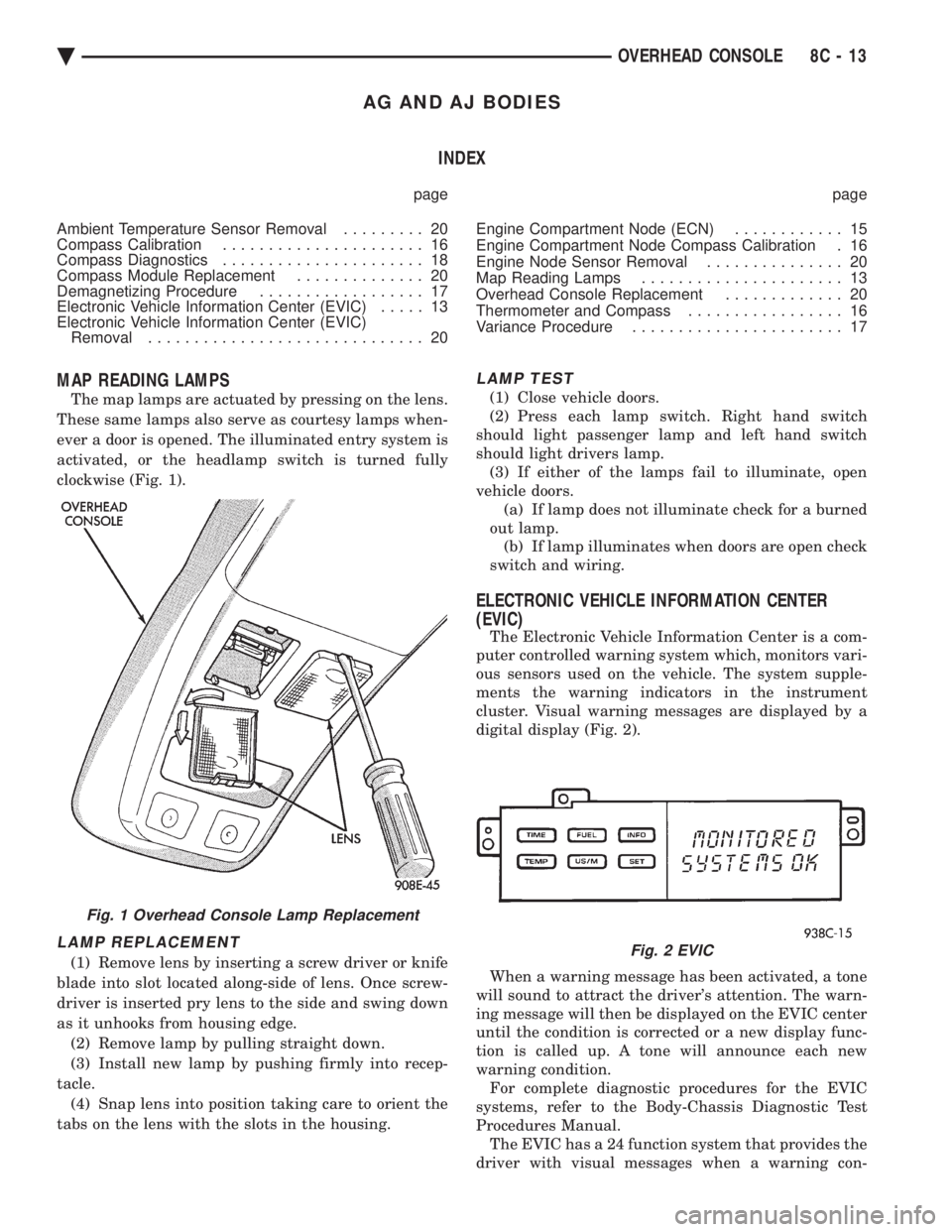
digital display (Fig. 2).
When a warning message has been activated, a tone
will sound to attract the driver's attention. The warn-
ing message will then be displayed on the EVIC center
until the condition is corrected or a new display func-
tion is called up. A tone will announce each new
warning condition. For complete diagnostic procedures for the EVIC
systems, refer to the Body-Chassis Diagnostic Test
Procedures Manual. The EVIC has a 24 function system that provides the
driver with visual messages when a warning con-
Fig. 1 Overhead Console Lamp Replacement
Fig. 2 EVIC
Ä OVERHEAD CONSOLE 8C - 13
Page 437 of 2438

AP BODY INDEX
page page
Ambient Temperature Sensor Removal ........ 25
Compass Calibration ...................... 21
Compass Diagnostics ..................... 23
Compass Module Replacement .............. 25
Demagnetizing Procedure .................. 22 Map Reading Lamps Operation
.............. 21
Overhead Console Replacement ............. 25
Thermometer and Compass ................ 21
Variance Procedure ....................... 22
MAP READING LAMPS OPERATION
The map lamps are actuated by pressing on the
lens (Fig. 1).
LAMP REPLACEMENT
(1) Remove lens by inserting a screw driver or
knife blade into slot located along-side of lens. Once
screwdriver is inserted pry lens to the side and swing
down as it unhooks from housing edge. (2) Remove lamp by pulling straight down.
(3) Install new lamp by pushing firmly into recep-
tacle. (4) Snap lens into position taking care to orient
the tabs on the lens with the slots in the housing.
MAP LAMP TEST
(1) Press each lamp switch. Right hand switch
should light passenger lamp and left hand switch
should light drivers lamp. (2) If lamp does not illuminate check for a burned
out lamp, voltage, defective switch or faulty wiring.
THERMOMETER AND COMPASS
The ignition switch must be in the ON or ACCES-
SORY position before the temperature and compass
reading can be displayed. The Comp/Temp switch
turns the compass display on and off. The US/Metric
switch changes the temperature reading from Fahr-
enheit to Celsius (Fig. 2). When the vehicle is standing still, engine compart-
ment temperatures may be radiated to the tempera-
ture sensor. Therefore the most accurate ambient
temperature readings are displayed when the vehicle
is moving in a forward motion. When the ignition switch is in the ON position the
temperature display is updated every 5 minutes.
When the ignition switch is turned off the last dis-
played temperature reading stays in memory. When
the ignition switch is turned on again the thermom-
eter will display the memory temperature for 1
minute; then update the display to the actual tem-
perature within 5 minutes.
COMPASS CALIBRATION
Do not attempt to set the compass near large metal
objects, such as, other vehicles, large buildings, or
bridges. The compass unit automatically calibrates itself as
the vehicle is driven; therefore, no calibration should
be required. When the compass is first powered up,
the CAL light on the display should be on. The CAL
light will go off and the compass will be accurate af-
ter the vehicle completes one to three complete cir-
cles. If the vehicle's compass headings are inaccurate,
the compass also can be manually calibrated using
the following procedures: (1) Depress and hold down both the Comp/Temp
button and the U.S./Metric button. (2) The display will go off and after 5 seconds the
VAR light will come on. Continue to hold both but-
tons down. (3) In approximately 10 seconds, the CAL light
will come on. Release both buttons and the display
will show the heading and outside temperature. (4) Drive the vehicle 1 to 3 complete circles, with-
out turning ignition OFF. The CAL light will then
go off, showing the compass is calibrated.
Fig. 1 Overhead Console Lamp Replacement
Ä OVERHEAD CONSOLE 8C - 21
Page 443 of 2438

IGNITION SYSTEMS
CONTENTS
page page
2.2L TBI, 2.5L TBI, 2.5L MPI AND 3.0L IGNITION SYSTEMSÐDIAGNOSTIC PROCEDURES
..... 11
2.2L TBI, 2.5L TBI, 2.5L MPI AND 3.0L IGNI- TION SYSTEMSÐSERVICE PROCEDURES . 14
2.2L TBI, 2.5L TBI, 2.5L MPI AND 3.0L IGNI- TION SYSTEMSÐSYSTEM OPERATION .... 1
2.2L TURBO III, 3.3L AND 3.8L IGNITION SYSTEMÐDIAGNOSTIC PROCEDURES
.... 35
2.2L TURBO III, 3.3L AND 3.8L IGNITION SYSTEMÐSYSTEM OPERATION ......... 24
2.2L TURBO III, 3.3L AND 3.8L IGNITION SYSTEMSÐSERVICE PROCEDURES ...... 39
IGNITION SWITCH ...................... 45
SPECIFICATIONS ....................... 47
GENERAL INFORMATION
Throughout this group, references are made to par-
ticular vehicles by letter designation. A chart ex-
plaining the designations appears in the Introduction
Section of this manual.
2.2L TBI, 2.5L TBI, 2.5L MPI AND 3.0L IGNITION SYSTEMSÐSYSTEM OPERATION
INDEX
page page
Auto Shutdown (ASD) Relay and Fuel Pump Relay . 8
Coolant Temperature Sensor ................. 7
Distributor Cap ........................... 1
Distributor Pick-UpÐ3.0L Engine .............. 7
Distributor Pick-UpÐPCM Input ............... 6
General Information ........................ 1 Ignition Coil
.............................. 9
Manifold Absolute Pressure (MAP) Sensor ...... 8
Powertrain Control Module (PCM) ............. 6
Rotor .................................. 2
Spark Plug Cables ........................ 2
Spark Plugs ............................. 3
GENERAL INFORMATION
This section describes the ignition systems of the
2.2L TBI, 2.5L TBI, 2.5L MPI (flexible fuel AA-body)
and 3.0L engines. The Fuel Injection sections of Group 14 explain On
Board Diagnostics. Group 0, Lubrication and Maintenance, contains
general maintenance information for ignition related
items. The Owner's Manual also contains mainte-
nance information.
DISTRIBUTOR CAP
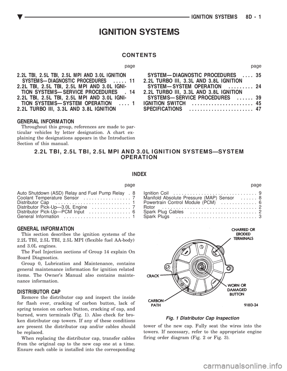
Remove the distributor cap and inspect the inside
for flash over, cracking of carbon button, lack of
spring tension on carbon button, cracking of cap, and
burned, worn terminals (Fig. 1). Also check for bro-
ken distributor cap towers. If any of these conditions
are present the distributor cap and/or cables should
be replaced. When replacing the distributor cap, transfer cables
from the original cap to the new cap one at a time.
Ensure each cable is installed into the corresponding tower of the new cap. Fully seat the wires into the
towers. If necessary, refer to the appropriate engine
firing order diagram (Fig. 2 or Fig. 3).
Fig. 1 Distributor Cap Inspection
Ä
IGNITION SYSTEMS 8D - 1