1993 CHEVROLET PLYMOUTH ACCLAIM Index
[x] Cancel search: IndexPage 144 of 2438

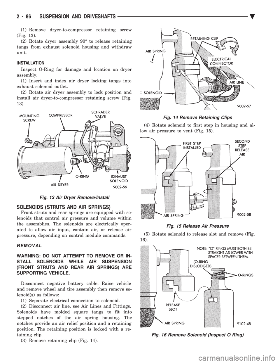
(1) Remove dryer-to-compressor retaining screw
(Fig. 13). (2) Rotate dryer assembly 90É to release retaining
tangs from exhaust solenoid housing and withdraw
unit.
INSTALLATION
Inspect O-Ring for damage and location on dryer
assembly. (1) Insert and index air dryer locking tangs into
exhaust solenoid outlet. (2) Rotate air dryer assembly to lock position and
install air dryer-to-compressor retaining screw (Fig.
13).
SOLENOIDS (STRUTS AND AIR SPRINGS)
Front struts and rear springs are equipped with so-
lenoids that control air pressure and volume within
the assemblies. The solenoids are electrically oper-
ated to allow air input, contain air, or release air
pressure, depending on control module commands.
REMOVAL
WARNING: DO NOT ATTEMPT TO REMOVE OR IN-
STALL SOLENOIDS WHILE AIR SUSPENSION
(FRONT STRUTS AND REAR AIR SPRINGS) ARE
SUPPORTING VEHICLE.
Disconnect negative battery cable. Raise vehicle
and remove wheel and tire assembly then remove so-
lenoid(s) as follows: (1) Separate electrical connection to solenoid.
(2) Disconnect air line, see Air Lines and Fittings.
Solenoids have molded square tangs to fit into
stepped notches of the air spring housing. The
notches provide an air relief position and a retaining
position. The retaining position is locked with a re-
taining clip. (3) Remove retaining clip (Fig. 14). (4) Rotate solenoid to first step in housing and al-
low air pressure to vent (Fig. 15).
(5) Rotate solenoid to release slot and remove (Fig.
16).
Fig. 13 Air Dryer Remove/Install
Fig. 14 Remove Retaining Clips
Fig. 15 Release Air Pressure
Fig. 16 Remove Solenoid (Inspect O Ring)
2 - 86 SUSPENSION AND DRIVESHAFTS Ä
Page 147 of 2438

REAR (STUB) AXLE ALIGNMENT ALL MODELS INDEX
page page
General Information ....................... 89 Rear Wheel Alignment..................... 89
GENERAL INFORMATION
Because front wheel drive vehicles are equipped with
rear suspension incorporating stub axles (or wheel
spindles). It is possible to align both the camber and toe
of the rear wheels.
REAR WHEEL ALIGNMENT
Alignment adjustment if required. Is made by adding
0.010 inch shims (from the service package kit) be-
tween the spindle mounting surface and axle mounting
plate. Each shim equals wheel change by .3É as shown
(for all car lines) in (Figs. 3 to 6). If rear wheel alignment is required, place vehicle on
alignment rack and check alignment specifications.
When recording rear toe-in (vehicle backed onto
alignment rack) REMEMBER to reverse sign
convention; a total toe-in on direct reading
charts is actually toe-out while driving. Maintain
rear alignment within Chrysler Motors recommenda-
tions, found in Specifications.
INSTALLATION OF REAR ALIGNMENT SHIMS
(1) Block front tires so vehicle will not move.
(2) Release parking brake.
(3) Hoist vehicle so that rear suspension is in full
rebound and tires are off the ground. See Hoisting in
Lubrication and Maintenance, Group 0. (4) Remove wheel and tire assembly.
(5) Pry off grease cap.
(6) Remove cotter pin and castle lock.
(7) Remove adjusting nut.
(8) Remove brake drum (Fig. 1). (9) Loosen four (4) brake assembly and spindle
mounting bolts enough to allow clearance for shim
installation (Fig. 2). Do not remove mounting
bolts.
(10) Install shims as shown in Figs. 3, 4, 5 and 6
for desired wheel change. No more than two shims
on each spindle should be used to bring alignment
within acceptable range. Wheel change by .3É per shim.
(11) Tighten down the 4 brake support plate and
spindle to axle mounting bolts until they are snug.
Then tighten the 4 bolts to the torque values listed
for the vehicle line which is being serviced.
² AA, AG, AJ, AP Bodies 75 N Im (55 ft. lbs.)
Fig. 2 Loosen Mounting Bolts
Fig. 3 Shim Installation for Toe-Out
Fig. 1 Remove Brake Drum
Ä SUSPENSION AND DRIVESHAFTS 2 - 89
Page 154 of 2438

SERVICE ADJUSTMENTS INDEX
page page
Adjusting Rear Service Brakes ............... 4
Bleeding Brake System ..................... 6
Brake Hose and Tubing ................... 11
Master Cylinder Fluid Level .................. 4 Stop Lamp Switch Adjustment (All Vehicles)
.... 13
Test for Fluid Contamination ................. 7
Testing Application Adjuster Operation ......... 6
Wheel Stud Nut Tightening .................. 7
MASTER CYLINDER FLUID LEVEL
ALL EXCEPT AC/AY BODY WITH ABS
Check master cylinder reservoir brake fluid level a
minimum of twice a year. Master cylinder reservoirs are marked with the
words fill to bottom of rings indicating proper fluid
level (Fig. 1). If necessary, add fluid to bring the level to the bot-
tom of the primary reservoir split ring. Use only Mopar tbrake fluid or an equivalent from
a sealed container. Brake fluid must conform to DOT
3, specifications. DO NOT use brake fluid with a lower boiling
point, as brake failure could result during prolonged
hard braking. Use only brake fluid that was stored in a tightly-
sealed container. DO NOT use petroleum-based fluid because seal
damage in the brake system will result.
AC AND AY BODY WITH ANTI-LOCK BRAKES
The hydraulic assembly is equipped with a plastic
fluid reservoir with a filter/strainer in the filler neck
of the reservoir. The Anti-Lock brake system requires that the hy-
draulic accumulator be de-pressurized whenever
checking the brake fluid level. To check the brake
fluid level, the following procedure should be used: (1) With the ignition switch turned to the off position
and key removed. De-pressurize hydraulic accumula-
tor by applying brake pedal approximately 40 times,
using a pedal force of approximately 220 N (50 lbs.). A
noticeable change in pedal feel will occur when accu-
mulator is de-pressurized. Continue to apply brake
pedal several times after this change in pedal feel
occurs to insure that brake system is fully de-
pressurized. (2) Thoroughly clean both reservoir caps and sur-
rounding area of reservoir, (Fig. 2) before removing
caps. This is to avoid getting dirt into the reservoir and
contaminating the brake fluid. (3) Inspect the brake fluid to see if it is at the proper
level, see instructions on top of reservoir. (FILL TO
TOP OF WHITE SCREEN ON FRONT
FILTER/STRAINER.) (4) Fill reservoir with brake fluid to top of screen
(Fig. 3) on the filter/strainer located in brake fluid
reservoir. Only use brake fluid conforming to DOT 3
specifications such as Mopar tor equivalent.
(5) Replace brake fluid reservoir caps.
ADJUSTING REAR SERVICE BRAKES
Normally, self adjusting drum brakes will not
require manual brake shoe adjustment. Al-
though in the event of a brake reline it is advis-
able to make the initial adjustment manually to
speed up the adjusting time. (1) Raise the vehicle so all wheels are free to turn.
See Hoisting Recommendations in the Lubrication And
Maintenance Section, at the front of this service
manual. (2) Remove rear brake adjusting hole rubber plug
(Fig. 4), from the rear brake shoe support plate. (3) Be sure parking brake lever is fully re-
leased. Then back off parking brake cable adjust-
ment so there is slack in the cable. (4) Insert Brake Adjuster, Special Tool C-3784, (Fig.
5) or equivalent through the adjusting hole in support
plate and against star wheel of adjusting screw. Move
handle of tool upward until a slight drag is felt when
the road wheel is rotated. (5) Insert a thin screwdriver or piece of welding rod
into brake adjusting hole (Fig. 5). Push adjusting lever
out of engagement with star wheel. Care
Fig. 1 Master Cylinder Fluid Level (All Except AC/AY
Body W/ABS)
5 - 4 BRAKES Ä
Page 168 of 2438

REAR WHEEL DRUM BRAKES INDEX
page page
Brake Drum Refacing ..................... 21
Brake Shoe Assemblies ................... 19 Description
............................. 18
Service Procedures ....................... 18
DESCRIPTION
Rear wheel drum brakes (Fig .2&3)aretwoshoe,
internal expanding type with an automatic adjuster
screw assembly that is activated each time the
brakes are applied. The automatic adjuster screw is
located directly below the wheel cylinder as shown in
figure (Fig .2&3).
WARNING: DUST AND DIRT ON BRAKE PARTS
GENERATED DURING THE NORMAL USE AND
WEAR OF MOTOR VEHICLE BRAKE SYSTEMS MAY
CONTAIN ASBESTOS FIBERS. BREATHING EXCES-
SIVE CONCENTRATIONS OF ASBESTOS FIBERS
CAN CAUSE SERIOUS BODILY HARM, SUCH AS
ASBESTOSIS AND CANCER. EXTREME CARE
SHOULD BE EXERCISED WHILE SERVICING
BRAKE ASSEMBLIES OR COMPONENTS. DO NOT CLEAN BRAKE ASSEMBLIES OR COM-
PONENTS WITH COMPRESSED AIR OR BY DRY
BRUSHING; USE A VACUUM CLEANER SPECIFI-
CALLY RECOMMENDED FOR USE WITH ASBES-
TOS FIBERS. IF A SUITABLE VACUUM CLEANER IS
NOT AVAILABLE, CLEANING SHOULD BE DONE
WET USING A WATER DAMPENED CLOTH. DO NOT CREATE DUST BY SANDING, GRINDING,
AND/OR SHAVING BRAKE LININGS OR PADS UN-
LESS SUCH OPERATION IS DONE WHILE USING
PROPERLY EXHAUST VENTILATED EQUIPMENT. DISPOSE OF ALL DUST AND DIRT SUSPECTED
TO CONTAIN ANY ASBESTOS FIBERS IN SEALED
BAGS OR CONTAINERS TO MINIMIZE DUST EXPO-
SURE TO YOURSELF AND OTHERS. FOLLOW ALL RECOMMENDED PRACTICES PRE-
SCRIBED BY THE OCCUPATIONAL SAFETY AND
HEALTH ADMINISTRATION AND THE ENVIRON-
MENTAL PROTECTION AGENCY. FOR THE HAN-
DLING, PROCESSING, AND DISPOSITION OF DUST
OR DIRT WHICH MAY CONTAIN ASBESTOS FI-
BERS. IT IS RECOMMENDED NOT TO BREATH ANY
TYPE OF BRAKE LINING MATERIAL DUST EVEN
ASBESTOS FREE, DUE TO THE FIBROUS NATURE
OF THE MATERIALS BEING USED.
SERVICE PROCEDURES
REAR BRAKE DRUM REMOVAL
If the rear brake drum is difficult to remove, fur-
ther clearance can be obtained by backing off the
brake automatic adjuster screw. Remove rubber plug
from the top of the support plate and rotate the au-
tomatic adjuster screw assembly with an upward mo-
tion, using the Brake Adjuster, Special Tool C-3784. See adjusting rear service brakes in the Service
Adjustments section in this group of the service man-
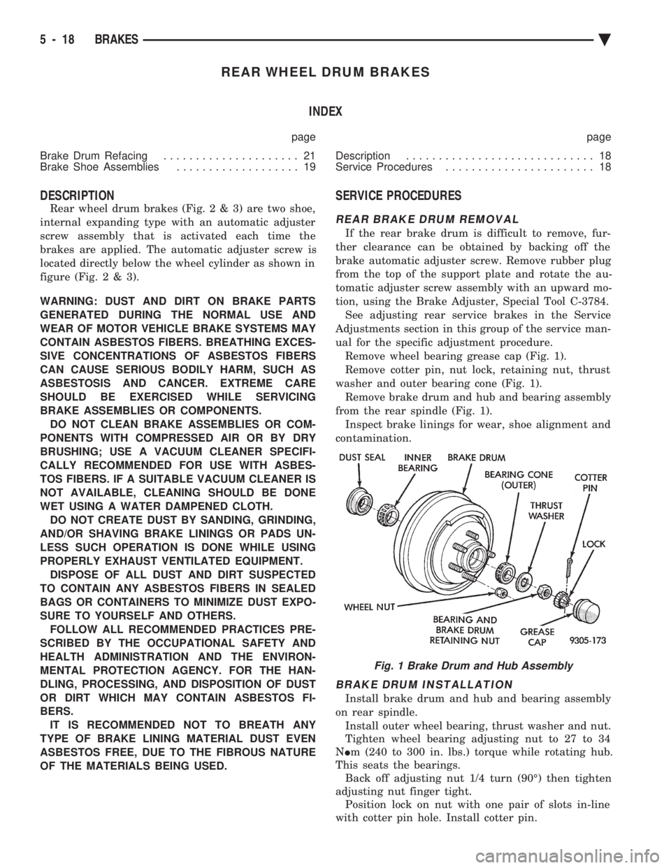
ual for the specific adjustment procedure. Remove wheel bearing grease cap (Fig. 1).
Remove cotter pin, nut lock, retaining nut, thrust
washer and outer bearing cone (Fig. 1). Remove brake drum and hub and bearing assembly
from the rear spindle (Fig. 1). Inspect brake linings for wear, shoe alignment and
contamination.
BRAKE DRUM INSTALLATION
Install brake drum and hub and bearing assembly
on rear spindle. Install outer wheel bearing, thrust washer and nut.
Tighten wheel bearing adjusting nut to 27 to 34
N Im (240 to 300 in. lbs.) torque while rotating hub.
This seats the bearings. Back off adjusting nut 1/4 turn (90É) then tighten
adjusting nut finger tight. Position lock on nut with one pair of slots in-line
with cotter pin hole. Install cotter pin.
Fig. 1 Brake Drum and Hub Assembly
5 - 18 BRAKES Ä
Page 173 of 2438

WHEEL CYLINDERS INDEX
page page
General Information ....................... 23
Installing Wheel Cylinders .................. 24 Service Procedures
....................... 23
GENERAL INFORMATION
The piston boots are of the push-on type and pre-
vent moisture from entering the wheel cylinder. To perform service operations or inspections of the
rear wheel brake cylinders. It will be necessary to re-
move the cylinders from the support plate and disas-
semble on the bench.
CAUTION: Wheel cylinders with cup expanders
must have cup expanders after any service proce-
dures (reconditioning or replacement).
SERVICE PROCEDURES
REMOVING WHEEL CYLINDERS FROM BRAKE SUPPORT PLATES
With brake drums removed, inspect the wheel cyl-
inder boots for evidence of a brake fluid leak. Then
block the brake pedal in the stroke position, and vi-
sually check the boots for cuts, tears, or heat cracks.
If any of these conditions exist, the wheel cylinders
should be completely cleaned, inspected and new
parts installed. (A slight amount of fluid on the boot
may not be a leak, but may be preservative fluid
used at assembly.) (1) In case of a leak, remove brake shoes, (replace
if soaked with grease or brake fluid.) (2) Thoroughly clean area of wheel cylinder, where
hydraulic brake line connects to wheel cylinder. Dis-
connect hydraulic brake tube from wheel cylinder
(Fig. 1). (3) Remove the rear wheel cylinder attaching bolts
(Fig. 1). Then pull wheel cylinder assembly off the
brake support plate (Fig. 2). (4) Clean the surface sealant off the support plate
and wheel cylinder surfaces.
DISASSEMBLING WHEEL CYLINDERS
To disassemble the wheel cylinders, (Fig. 3) pro-
ceed as follows: (1) Pry boots away from cylinders and remove.
(2) Press INon one piston to force out opposite pis-
ton, cup and spring (with cup expanders). Then using
a soft tool such as a dowel rod, press out the cup and
piston that remain in the wheel cylinder. (3) Wash wheel cylinder, pistons, and spring in
clean brake fluid or alcohol; (DO NOT USE ANY
PETROLEUM BASE SOLVENTS) clean thor- oughly and blow dry with compressed air. Inspect
Fig. 1 Brake Tube Disconnected
Fig. 2 Remove or Install Wheel Cylinder
Ä
BRAKES 5 - 23
Page 176 of 2438

HYDRAULIC SYSTEM CONTROL VALVES INDEX
page page
ABS Brake Proportioning Valve Operation ...... 27
General Information ....................... 26
Hydraulic System Service Procedures ......... 27 Non-ABS Proportioning Unit Operation
........ 26
Pressure Differential Warning Light Switch ...... 26
Testing ABS Proportioning Valves ............ 29
GENERAL INFORMATION
Most models not equipped with an Anti-Lock brak-
ing system have a combination hydraulic system con-
trol valve in the brake hydraulic system (Fig. 1). The
valve is attached to the frame rail below the master
cylinder.
The control valve assembly combines a warning
switch with a dual proportioning valve (Fig. 2) Proportioning valves balance front to rear braking
by controlling at a given ratio, the increase in rear
system hydraulic pressure above a preset level. Un-
der light pedal application, the valve allows full hy-
draulic pressure to the rear brakes. There is only one valve assembly in each vehicle,
see Valve Application Chart. During any service pro-
cedures identify valve assemblies by part number as
well as split point (PSI) and slope.
PRESSURE DIFFERENTIAL WARNING LIGHT
SWITCH
The hydraulic brake system, on non-ABS vehicles,
is split diagonally. The left front and right rear
brakes are part of one system. And the right front and left rear are part of another. Both systems are
routed through, but hydraulically separated by a Pres-
sure Differential Switch. The function of the Pressure
Differential Switch is to alert the driver of a malfunc-
tion in the brake system. If hydraulic pressure is lost in one system, the
warning light switch will activate a red light on the
instrument panel, when the brake pedal is depressed.
At this point the brakes require service. However, since
the brake systems are split diagonally the vehicle will
retain 50% of its stopping capability in the event of a
failure in either half. The warning light switch is the latching type. It
will automatically center itself after the repair is
made and the brake pedal is depressed. The instrument panel bulb can be checked each time
the ignition switch is turned to the start position or the
parking brake is set.
NON-ABS PROPORTIONING UNIT OPERATION
The proportioning valve section operates by trans-
mitting full input pressure to the rear brakes up to a
certain point. This is called the split point. Beyond this
point it reduces the amount of pressure increase to the
rear brakes according to a certain ratio. On light pedal applications equal brake pressure will
be transmitted to the front and rear brakes. On heavier
pedal applications the pressure transmitted
Fig. 1 Brake Combination Valve And Warning Switch Location
Fig. 2 Switch and Valve Assembly
5 - 26 BRAKES Ä
Page 181 of 2438

FRONT DISC BRAKES INDEX
page page
General Information ....................... 31
Service Precautions ....................... 34 Shoe and Lining Wear
.................... 33
GENERAL INFORMATION
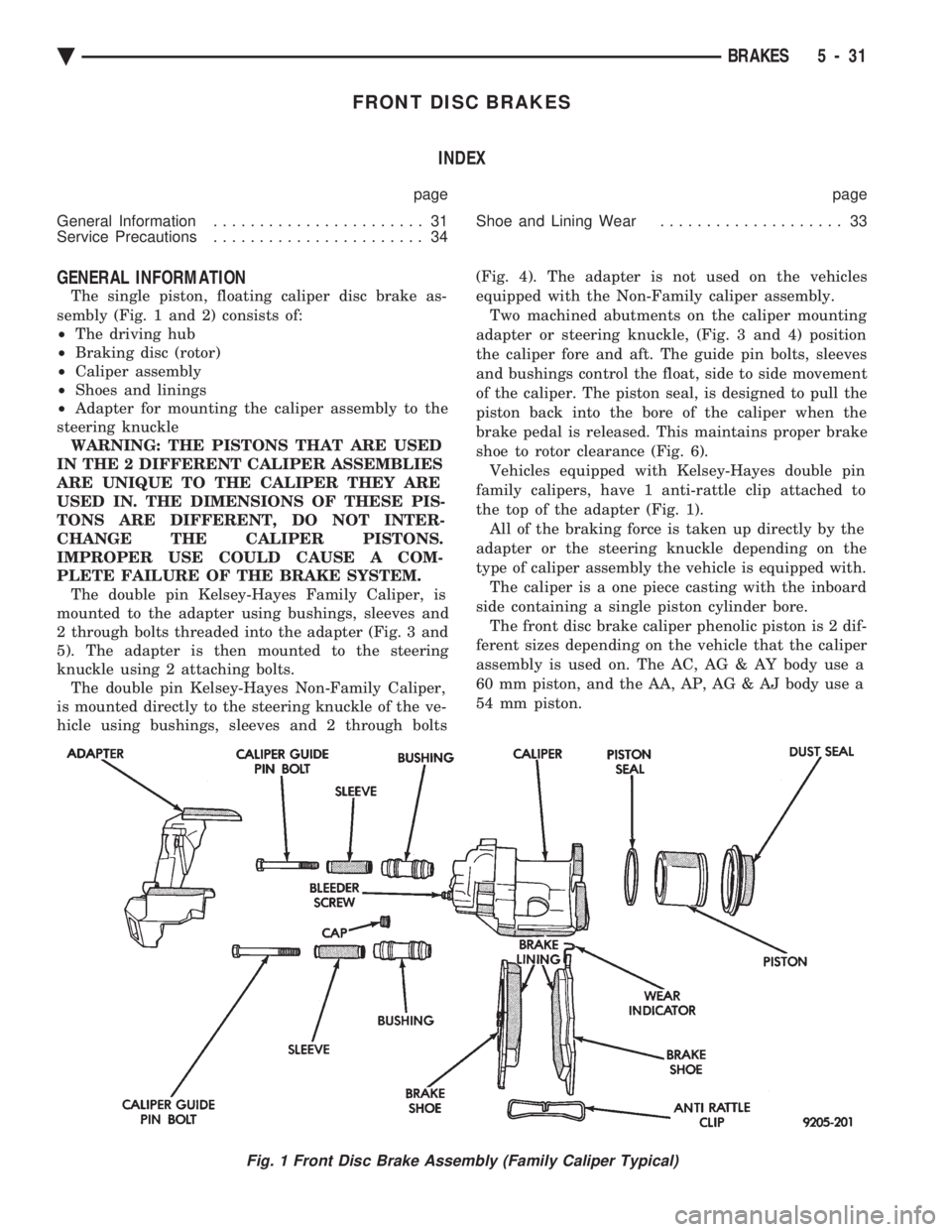
The single piston, floating caliper disc brake as-
sembly (Fig. 1 and 2) consists of:
² The driving hub
² Braking disc (rotor)
² Caliper assembly
² Shoes and linings
² Adapter for mounting the caliper assembly to the
steering knuckle WARNING: THE PISTONS THAT ARE USED
IN THE 2 DIFFERENT CALIPER ASSEMBLIES
ARE UNIQUE TO THE CALIPER THEY ARE
USED IN. THE DIMENSIONS OF THESE PIS-
TONS ARE DIFFERENT, DO NOT INTER-
CHANGE THE CALIPER PISTONS.
IMPROPER USE COULD CAUSE A COM-
PLETE FAILURE OF THE BRAKE SYSTEM. The double pin Kelsey-Hayes Family Caliper, is
mounted to the adapter using bushings, sleeves and
2 through bolts threaded into the adapter (Fig. 3 and
5). The adapter is then mounted to the steering
knuckle using 2 attaching bolts. The double pin Kelsey-Hayes Non-Family Caliper,
is mounted directly to the steering knuckle of the ve-
hicle using bushings, sleeves and 2 through bolts (Fig. 4). The adapter is not used on the vehicles
equipped with the Non-Family caliper assembly.
Two machined abutments on the caliper mounting
adapter or steering knuckle, (Fig. 3 and 4) position
the caliper fore and aft. The guide pin bolts, sleeves
and bushings control the float, side to side movement
of the caliper. The piston seal, is designed to pull the
piston back into the bore of the caliper when the
brake pedal is released. This maintains proper brake
shoe to rotor clearance (Fig. 6). Vehicles equipped with Kelsey-Hayes double pin
family calipers, have 1 anti-rattle clip attached to
the top of the adapter (Fig. 1). All of the braking force is taken up directly by the
adapter or the steering knuckle depending on the
type of caliper assembly the vehicle is equipped with. The caliper is a one piece casting with the inboard
side containing a single piston cylinder bore. The front disc brake caliper phenolic piston is 2 dif-
ferent sizes depending on the vehicle that the caliper
assembly is used on. The AC, AG & AY body use a
60 mm piston, and the AA, AP, AG & AJ body use a
54 mm piston.
Fig. 1 Front Disc Brake Assembly (Family Caliper Typical)
Ä BRAKES 5 - 31
Page 188 of 2438

KELSEY HAYES DOUBLE PIN NON-FAMILY CALIPER INDEX
page page
Assembling Disc Brake Caliper .............. 42
Cleaning and Inspection of Brake Caliper ...... 41 Disc Brake Caliper Disassembly
............. 40
Service Procedures ....................... 38
SERVICE PROCEDURES
BRAKE SHOES REMOVE
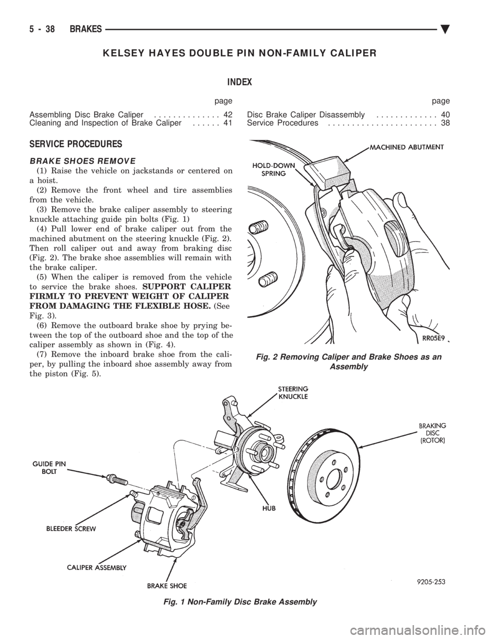
(1) Raise the vehicle on jackstands or centered on
a hoist. (2) Remove the front wheel and tire assemblies
from the vehicle. (3) Remove the brake caliper assembly to steering
knuckle attaching guide pin bolts (Fig. 1) (4) Pull lower end of brake caliper out from the
machined abutment on the steering knuckle (Fig. 2).
Then roll caliper out and away from braking disc
(Fig. 2). The brake shoe assemblies will remain with
the brake caliper. (5) When the caliper is removed from the vehicle
to service the brake shoes. SUPPORT CALIPER
FIRMLY TO PREVENT WEIGHT OF CALIPER
FROM DAMAGING THE FLEXIBLE HOSE. (See
Fig. 3). (6) Remove the outboard brake shoe by prying be-
tween the top of the outboard shoe and the top of the
caliper assembly as shown in (Fig. 4). (7) Remove the inboard brake shoe from the cali-
per, by pulling the inboard shoe assembly away from
the piston (Fig. 5).
Fig. 1 Non-Family Disc Brake Assembly
Fig. 2 Removing Caliper and Brake Shoes as an Assembly
5 - 38 BRAKES Ä